RILEM TC “Reinforcement of Timber Elements in Existing Structures ...
RILEM TC “Reinforcement of Timber Elements in Existing Structures ...
RILEM TC “Reinforcement of Timber Elements in Existing Structures ...

Create successful ePaper yourself
Turn your PDF publications into a flip-book with our unique Google optimized e-Paper software.
Materials and methods. Both T0 and T1 consisted <strong>of</strong> four-po<strong>in</strong>t bend<strong>in</strong>g tests <strong>of</strong> the unre<strong>in</strong>forced<br />
and re<strong>in</strong>forced beams up to failure. Previously, elastic bend<strong>in</strong>g tests were performed <strong>in</strong> order to<br />
determ<strong>in</strong>e the MOE <strong>of</strong> the considered elements. After determ<strong>in</strong><strong>in</strong>g the MOE <strong>of</strong> every s<strong>in</strong>gle<br />
element, the composite beams without mechanical connections were tested. This way it was<br />
possible to evaluate to what extent the beams and planks worked together as parallel elements or<br />
whether they were affected by phenomena such as friction. Eventually, once the connectors were<br />
applied, the result<strong>in</strong>g composite beams were tested elastically, and the stiffness <strong>of</strong> re<strong>in</strong>forced floor<br />
was determ<strong>in</strong>ed. Subsequently all specimens were tested up to failure. T2 tests were performed on<br />
three beams, two were cambered follow<strong>in</strong>g the <strong>in</strong>sertion procedure (Int-to-Ext) and one (Ext-to-Int).<br />
The three assembled specimens were monitored for 48 hours, to detect any camber loss.<br />
Results and discussion. An important <strong>in</strong>formation gathered from T0 and T1 was the efficiency <strong>of</strong><br />
the connection µ used <strong>in</strong> the re<strong>in</strong>forcement, rang<strong>in</strong>g from µ = 0 (EJef = EJ0) to µ = 1 (EJef = EJ∞),<br />
where EJef is the bend<strong>in</strong>g stiffness <strong>of</strong> the re<strong>in</strong>forced beam, EJ0 is the bend<strong>in</strong>g stiffness <strong>of</strong> the<br />
unre<strong>in</strong>forced beam, and EJ∞ is the theoretic bend<strong>in</strong>g stiffness <strong>of</strong> the composite beam with an ideal<br />
(completely stiff) connection. The performed tests demonstrated that the re<strong>in</strong>forced floors behaved<br />
very similarly to the ideal composite beam, with µ be<strong>in</strong>g 95-96 %.<br />
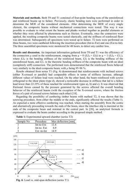
Results obta<strong>in</strong>ed from series T1 (Fig. 6) demonstrated that re<strong>in</strong>forcements with <strong>in</strong>cl<strong>in</strong>ed screws<br />
(either X-crossed or parallel) had comparable effects <strong>in</strong> terms <strong>of</strong> stiffness <strong>in</strong>crease, although<br />
different values <strong>of</strong> failure load were reached. On the other hand, the beam re<strong>in</strong>forced with screws<br />
orthogonal to the shear plane (type d), showed a noticeable decrease <strong>in</strong> stiffness that led to a failure<br />
load lower than 22-35% <strong>of</strong> those reached for re<strong>in</strong>forcement types a), b) and c). It was observed that<br />
frictional forces caused by the pressure generated by the screws affected the overall bend<strong>in</strong>g<br />
behavior <strong>of</strong> the re<strong>in</strong>forced beams (with the exception <strong>of</strong> the X-crossed screws, where the friction<br />
forces <strong>of</strong> a pair <strong>of</strong> crossed screws balance each other) [18].<br />
Regard<strong>in</strong>g the possibility <strong>of</strong> camber<strong>in</strong>g timber beams with method T2, it was shown that the<br />
screw<strong>in</strong>g procedure, from either the middle or the ends, significantly affected the results (Table 1).<br />
As expected a more effective camber<strong>in</strong>g was reached, when start<strong>in</strong>g the assembly from the centre<br />
and alternatively proceed<strong>in</strong>g towards the ends <strong>of</strong> the beam, s<strong>in</strong>ce the <strong>in</strong>terface slip is maximal at the<br />
ends <strong>of</strong> the composite beam and m<strong>in</strong>imal <strong>in</strong> the central part. In [20], an analytical formula is<br />
expressed to evaluate the beam camber accord<strong>in</strong>g to the proposed simple method.<br />
[kN]<br />
140<br />
120<br />
Table 1: Experimental upward chamber (series T2)<br />
Sample No Procedure Max deflection [mm]<br />
1 Int-to-Ext 13.4<br />
2 Int-to- Ext 6.9<br />
3 Ext -to-Int 14.9<br />
110,3 kN<br />
Load Vs. Midspan deflection<br />
125,5 kN<br />
100<br />
80<br />
60<br />
40<br />
92.6 kN<br />
72,0 kN<br />
a)<br />
Floor 1<br />
b)<br />
Floor 2<br />
c)<br />
Floor 3<br />
d)<br />
Floor 4<br />
20<br />
0<br />
0 50 100 150 200 250<br />
[mm]<br />
Fig. 6: Load vs. mid-span deflection (series T1)