Wheelock - Cooper Industries
Wheelock - Cooper Industries
Wheelock - Cooper Industries

Create successful ePaper yourself
Turn your PDF publications into a flip-book with our unique Google optimized e-Paper software.
WARNING: MAKE SURE THAT THE TOTAL RMS CURRENT REQUIRED BY ALL APPLIANCES THAT ARE CONNECTED TO THE<br />
SYSTEM’S PRIMARY AND SECONDARY POWER SOURCES, NOTIFICATION APPLICIANCE CIRCUITS, SM, DSM SYNC MODULES, OR<br />
WHEELOCK POWER SUPPLIES DOES NOT EXCEED THE POWER SOURCES’ RATED CAPACITY OR THE CURRENT RATINGS OF ANY FUSES<br />
ON THE CIRCUITS TO WHICH THESE APPLIANCES ARE WIRED. OVERLOADING POWER SOURCES OR EXCEEDING FUSE RATINGS<br />
COULD RESULT IN LOSS OF POWER AND FAILURE TO ALERT OCCUPANTS DURING AN EMERGENCY, WHICH COULD RESULT IN<br />
PROPERTY DAMAGE AND SERIOUS INJURY OR DEATH TO YOU AND/OR OTHERS.<br />
WIRING AND MOUNTING INFORMATION:<br />
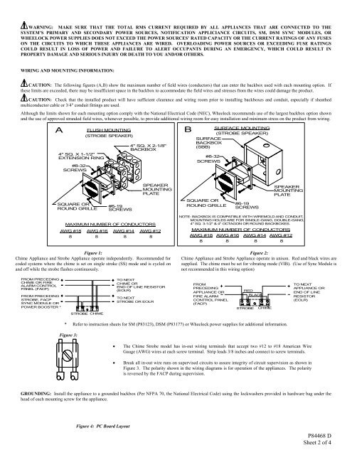
CAUTION: The following figures (A,B) show the maximum number of field wires (conductors) that can enter the backbox used with each mounting option. If<br />
these limits are exceeded, there may be insufficient space in the backbox to accommodate the field wires and stresses from the wires could damage the product.<br />
CAUTION: Check that the installed product will have sufficient clearance and wiring room prior to installing backboxes and conduit, especially if sheathed<br />
multiconductor cable or 3/4" conduit fittings are used.<br />
Although the limits shown for each mounting option comply with the National Electrical Code (NEC), <strong>Wheelock</strong> recommends use of the largest backbox option shown<br />
and the use of approved stranded field wires, whenever possible, to provide additional wiring room for easy installation and minimum stress on the product from wiring.<br />
A<br />
4" SQ. X 1-1/2"<br />
EXTENSION RING *<br />
#8-32<br />
SCREWS<br />
FLUSH MOUNTING<br />
(STROBE SPEAKER)<br />
4" SQ. X 2-1/8"<br />
BACKBOX<br />
B<br />
SURFACE MOUNTING<br />
(STROBE SPEAKER)<br />
SURFACE<br />
BACKBOX<br />
(SBB)<br />
#8-32<br />
SCREWS<br />
SQUARE OR<br />
ROUND GRILLE<br />
#6-19<br />
SCREWS<br />
SPEAKER<br />
MOUNTING<br />
PLATE<br />
SQUARE OR<br />
ROUND GRILLE<br />
#6-19<br />
SCREWS<br />
SPEAKER<br />
MOUNTING<br />
PLATE<br />
MAXIMUM NUMBER OF CONDUCTORS<br />
AWG #18 AWG #16<br />
8 8<br />
AWG #14<br />
AWG #12<br />
8 8<br />
Figure 1:<br />
Chime Appliance and Strobe Appliance operate independently. Recommended for<br />
coded systems where the chime is set on single stroke (SS) mode and is cycled on<br />
and off while the strobe flashes continuously.<br />
NOTE: BACKBOX IS COMPATIBLE WITH WIREMOLD AND CONDUIT,<br />
MOUNTING HOLES ARE FOR SINGLE-GANG, DOUBLE-GANG,<br />
4" SQ. 3-1/2" & 4" OCTAGON OR ROUND BACKBOXES.<br />
MAXIMUM NUMBER OF CONDUCTORS<br />
AWG #18 AWG #16<br />
8 8<br />
AWG #14<br />
AWG #12<br />
8 8<br />
Figure 2:<br />
Chime Appliance and Strobe Appliance operate in unison. Red and black wires are<br />
supplied. The chime must be set for vibrating mode (VIB). (Use of Sync Module is<br />
not recommended in this wiring option)<br />
FROM PRECEDING<br />
CHIME OR FIRE<br />
ALARM CONTROL<br />
PANEL (FACP)<br />
FROM PRECEDING<br />
STROBE, FACP<br />
SYNC MODULE OR<br />
POWER BOOSTER *<br />
TO NEXT<br />
CHIME OR<br />
END OF LINE RESISTOR<br />
(EOLR)<br />
TO NEXT<br />
STROBE OR EOLR<br />
FROM<br />
PRECEDING<br />
APPLIANCE OR<br />
FIRE ALARM<br />
CONTROL PANEL<br />
(FACP)<br />
RED<br />
BLACK<br />
STROBE CHIME<br />
TO NEXT<br />
APPLIANCE OR<br />
END OF LINE<br />
RESISTOR<br />
(EOLR)<br />
STROBE CHIME<br />
* Refer to instruction sheets for SM (P83123), DSM (P83177) or <strong>Wheelock</strong> power supplies for additional information.<br />
Figure 3:<br />
• The Chime Strobe model has in-out wiring terminals that accept two #12 to #18 American Wire<br />
Gauge (AWG) wires at each screw terminal. Strip leads 3/8 inches and connect to screw terminals.<br />
• Break all in-out wire runs on supervised circuits to assure integrity of circuit supervision as shown in<br />
Figure 3. The polarity shown in the wiring diagrams is for operation of the appliances. The polarity<br />
is reversed by the FACP during supervision.<br />
GROUNDING: Install the appliance to a grounded backbox (Per NFPA 70, the National Electrical Code) using the lockwashers provided in hardware bag under the<br />
head of each mounting screw for the appliance.<br />
Figure 4: PC Board Layout<br />
P84468 D<br />
Sheet 2 of 4