Kit 64. 90/120 Second Message Recorder - The Free Information ...
Kit 64. 90/120 Second Message Recorder - The Free Information ...
Kit 64. 90/120 Second Message Recorder - The Free Information ...

You also want an ePaper? Increase the reach of your titles
YUMPU automatically turns print PDFs into web optimized ePapers that Google loves.
<strong>Kit</strong> <strong>64.</strong> <strong>90</strong>/<strong>120</strong> <strong>Second</strong> <strong>Message</strong> <strong>Recorder</strong><br />
<strong>Information</strong> Storage Devices are one of the leaders in solid<br />
state audio recording & playback devices. <strong>The</strong> latest<br />
ISD25xx series provides high-quality, single-chip, nonvolatile<br />
record/playback for 45, 60, 75, <strong>90</strong> and now <strong>120</strong><br />
seconds. <strong>The</strong>se cmos devices include an on-chip<br />
oscillator, microphone preamplifier, automatic gain control,<br />
antialiasing filter, smoothing filter and speaker amplifier. In<br />
addition it is micro-processor compatible allowing complex<br />
messaging and addressing to be achieved.<br />
Recordings are stored in on-board non-volatile memory<br />
cells, providing zero power message storage. <strong>The</strong><br />
proprietary storage method allows natural voice analog<br />
storage. <strong>The</strong> purpose of this <strong>Kit</strong> is to introduce you to this<br />
modern, new technology.<br />
Our Circuit. We now use the ISD25<strong>120</strong>, <strong>120</strong> second audio<br />
recording IC in this kit. <strong>The</strong> ISD25<strong>120</strong> has several modes<br />
of operation We use it here as a multi-message recorder.<br />
You may record as many messages as you want up to <strong>120</strong><br />
seconds of memory space. Put the SPDT switch into the<br />
Record position and just push & release the Start/Pause<br />
button to start recording. <strong>The</strong> Record LED goes on. Push<br />
the Start/Pause button to Pause - stop recording. That is<br />
the end of <strong>Message</strong> 1.<br />
Sometime later you can record a follow on message,<br />
<strong>Message</strong> 2, by pushing the Start/Pause button again.<br />
When you put the switch to Play the messages will<br />
playback. Only one message will be played back at a time.<br />
You must push Start/Pause again to get the next message.<br />
<strong>The</strong> Reset switch will move the internal address pointer<br />
back to the start of the memory space.<br />
Removing the power will not destroy the messages. You<br />
may, for example, record a long message, then send just<br />
the IC to someone through the mail then the friend could<br />
playback your message. This is the same as the 20 second<br />
Greeting Cards now on the market. <strong>The</strong>y use a ISD1420<br />
chip-on-board IC.<br />
Build up the <strong>Kit</strong> and start playing with it. Far better to<br />
learn about it from actual use than reading pages about<br />
how it works!<br />
You can get more about applications and memory<br />
addressing of the ISD25<strong>90</strong> from the website at<br />
http://www.isd.com<br />
Unfortunately ISD have not put up the data sheet on the<br />
ISD25xxx at this time (11/99.)<br />
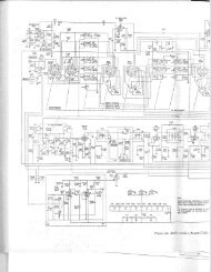
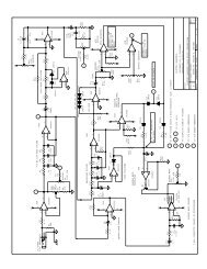
Construction. We have placed some of the components<br />
underneath the IC. This was not only to reduce the size of<br />
the PCB. Because the ISD products are top quality we<br />
wanted to follow their recommended audio design<br />
practices:<br />
• analog components are placed physically close to the<br />
IC with short leads<br />
• analog and digital power & ground tracks have been<br />
kept separate<br />
• large power & ground tracks have been used as much<br />
as possible even between IC pads<br />
R1 & R8 are just able to squeeze in between the sides of<br />
the IC socket. If there is a problem use your soldering iron<br />
to burn a small groove in the IC socket.<br />
<strong>The</strong> 1uF mini electrolytic capacitor C7 will fold over next to<br />
R11 quite comfortably. NOTE: there is one link to make<br />
under the socket. Use some wire cut off from a resistor to<br />
make the link.<br />
Operation<br />
When you first use the <strong>Recorder</strong> attach a speaker (4 ohm<br />
or 8 ohm) to the Output and record & play-back your<br />
messages as previously described.<br />
If you want more loudness ISD suggest that one way to<br />
do so is to limit the low end frequency response. With C4<br />
& C6 at 0.1uF, signals above 160Hz are not attenuated.<br />
Changing these capacitors to 0.01uF increases this low<br />
end pole to 1500Hz. Since small speakers do not reproduce<br />
the low frequencies efficiently this change may give you<br />
an increase in loudness.<br />
If you want to amplify the output the differential output<br />
may be fed directly to audio equipment with a differential<br />
input. Or you may use an amplifier like an LM386. If you<br />
use the amplifier between one output pin (either pin 14 or<br />
15) and ground it is very important that the unused output<br />
pin not be grounded. It must be left unconnected.<br />
If It Does Not Work. Check that the diodes are all in the<br />
correct way. Are the resistors in the right places. Check<br />
that the TO-92 packaged components are in their correct<br />
places. Are the capacitors, microphone & LEDs the correct<br />
way around.<br />
More on the ISD25xxx<br />
<strong>The</strong> power of the chip lies in the fact that the memory<br />
space is computer addressable. In the ISD25xx there are<br />
600 (six hundred) addressable message segments. So in<br />
the ISD2560, for example, you can record a maximum of<br />
600 messages each 100 msec long. So who wants 600<br />
1/100th second messages? Well think of a talking<br />
voltmeter. No more would you have to put the probes on<br />
then move your head & eyes to read the display. <strong>The</strong><br />
meter would say "six point two five volts". <strong>The</strong> spoken<br />
numerals plus the teens, tens & other quantifiers would<br />
only occupy the exact memory space they need to the next<br />
1/100th of a second. <strong>The</strong> micro-controllers job is to quickly<br />
search through the address space and put together the<br />
required message output in real time.
<strong>Kit</strong> <strong>64.</strong> <strong>90</strong>/<strong>120</strong> <strong>Second</strong> <strong>Message</strong> <strong>Recorder</strong><br />
Think of a burglar alarm system: both the setting of it and<br />
the spoken messages it could give (over the phone after<br />
using the DTMF tones of phone numbers stored in<br />
ISD25xx memory too) after it was set off. Think of setting a<br />
VCR: instruction about how to set it can be spoken<br />
to you. And there would even be space for ‘Have a nice<br />
day at the end of it.<br />
Also ISD25xx chips can (with one exception) be<br />
seamlessly connected together to give increased message<br />
time. By seamless is meant that a message can straddle 2<br />
physical IC's. (Earlier ISD chips could not do this.) See the<br />
Jeff Bachiochi article for more details.<br />
References:<br />
Bachiochi, Jeff. (1994). Build the <strong>Message</strong> Board. Circuit<br />
Cellar Ink/<strong>The</strong> Computer Applications Journal 45, April, 54<br />
- 61. (Uses ISD2500 under computer control.)<br />
Yates, Darren. (1994). Build this <strong>90</strong>-second <strong>Message</strong><br />
Board. Silicon Chip, February, 16 - 19. (Uses ISD25<strong>90</strong>.)<br />
For other voice recording <strong>Kit</strong>s see our <strong>Kit</strong> 131, 30 <strong>Second</strong><br />
Voice <strong>Recorder</strong> using a different non-volatile IC.<br />
See our website at http://kitsrus.com<br />
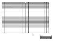
COMPONENTS<br />
Resistors:<br />
680R blue grey brown R5 R6 2<br />
1K brown black red R7 1<br />
4K7 yellow violet red R2 1<br />
10K brown black orange R8 R9 2<br />
22K red red orange R3 R4 2<br />
100K brown black yellow R10 R11 2<br />
470K yellow violet yellow R1 1<br />
Capacitors:<br />
0.1 Monoblock 104 C1 C2 C4 C6 4<br />
1uF electrolytic mini C7 1<br />
4.7uF elcap C8 1<br />
100uF elcap C3 1<br />
220uF elcap C5 1<br />
BC547 Q1 Q2 2<br />
BC557 Q3 1<br />
ISD25<strong>120</strong> IC 1<br />
28 pin IC socket 1<br />
1N4148 diode 1<br />
2 pole terminal block 2<br />
Electret Microphone 1<br />
Hat keyswitch 2<br />
5mm LED 2<br />
K64 PCB 1<br />
SPDT PCB mounted switch 1
<strong>Kit</strong> <strong>64.</strong> <strong>90</strong>/<strong>120</strong> <strong>Second</strong> <strong>Message</strong> <strong>Recorder</strong>