HARTING News 2013
HARTING News 2013
HARTING News 2013

You also want an ePaper? Increase the reach of your titles
YUMPU automatically turns print PDFs into web optimized ePapers that Google loves.
<strong>HARTING</strong> <strong>News</strong> <strong>2013</strong>
<strong>HARTING</strong> worldwide<br />
Introduction<br />
Transforming customer wishes<br />
into concrete solutions<br />
The <strong>HARTING</strong> Technology Group is skilled in the fields of electrical, electronic and optical<br />
connection, transmission and networking, as well as in manufacturing, mechatronics and<br />
software creation. The Group uses these skills to develop customized solutions and products<br />
such as connectors for energy and data transmission applications including, for example,<br />
mechanical engineering, rail technology, wind energy plants, factory automation and the<br />
telecommunications sector. In addition, <strong>HARTING</strong> also produces electro-magnetic components<br />
for the automobile industry and offers solutions in the field of Enclosures and Shop Systems.<br />
The <strong>HARTING</strong> Group currently comprises 36 subsidiary companies and worldwide distributors<br />
employing a total of approximately 3,500 staff.<br />
2
Introduction<br />
<strong>HARTING</strong> Subsidiary company<br />
<strong>HARTING</strong> Representatives<br />
We aspire to top performance.<br />
Connectors ensure functionality. As core elements<br />
of electrical and optical wiring, connection and<br />
infrastructure technologies, they are essential in<br />
enabling the modular construction of devices, machines<br />
and systems across a very wide range of industrial<br />
applications. Their reliability is a crucial factor<br />
guaranteeing smooth functioning in the manufacturing<br />
area, in telecommunications, applications in medical<br />
technology – in fact, connectors are at work in virtually<br />
every conceivable application area. Thanks to the<br />
consistent further development of our technologies,<br />
customers enjoy investment security and benefit from<br />
durable, long term functionality.<br />
Always at hand, wherever our customers may be.<br />
Increasing industrialization is creating growing<br />
markets characterized by widely diverging demands and<br />
requirements. The search for perfection, increasingly<br />
efficient processes and reliable technologies is a common<br />
factor in all sectors across the globe.<br />
<strong>HARTING</strong> is providing these technologies – in Europe,<br />
America and Asia. The <strong>HARTING</strong> professionals at our<br />
international subsidiaries engage in close, partnership<br />
based interaction with our customers, right from the very<br />
early product development phases, in order to realize<br />
customer demands and requirements in the best possible<br />
manner.<br />
Our people on location form the interface to the centrally<br />
coordinated development and production departments.<br />
In this way, our customers can rely on consistently high,<br />
superior product quality – worldwide.<br />
Our claim: pushing performance.<br />
<strong>HARTING</strong> provides more than optimally attuned<br />
components. In order to serve our customers with the best<br />
possible solutions, <strong>HARTING</strong> is able to contribute a great<br />
deal more and play a closely integrative role in the value<br />
creation process.<br />
From ready assembled cables through to control racks<br />
or ready-to-go control desks: Our aim is to generate<br />
the maximum benefits for our customers – without<br />
compromise!<br />
Quality creates reliability – and warrants trust.<br />
The <strong>HARTING</strong> brand stands for superior quality and<br />
reliability – worldwide. The standards we set are the<br />
result of consistent, stringent quality management that is<br />
subject to regular certifications and audits.<br />
EN ISO 9001, the EU Eco-Audit and ISO 14001:2004 are<br />
key elements here. We take a proactive stance to new<br />
requirements, which is why <strong>HARTING</strong> ranks among the<br />
first companies worldwide to have obtained the new IRIS<br />
quality certificate for rail vehicles.<br />
3
<strong>HARTING</strong> worldwide<br />
Introduction<br />
<strong>HARTING</strong> technology creates added value for customers.<br />
Technologies by <strong>HARTING</strong> are at work worldwide.<br />
<strong>HARTING</strong>’s presence stands for smoothly functioning<br />
systems, powered by intelligent connectors, smart<br />
infrastructure solutions and mature network systems. In<br />
the course of many years of close, trust-based cooperation<br />
with its customers, the <strong>HARTING</strong> Technology Group has<br />
advanced to one of the worldwide leading specialists<br />
for connector technology. Extending beyond the basic<br />
functionalities demanded, we offer individual customers<br />
specific and innovative solutions. These tailored solutions<br />
deliver sustained effects, provide investment security and<br />
enable customers to achieve strong added value.<br />
Opting for <strong>HARTING</strong> opens up an innovative, complex<br />
world of concepts and ideas.<br />
In order to develop connectivity and network solutions<br />
serving an exceptionally wide range of connector<br />
applications and task scopes in a professional and cost<br />
optimized manner, <strong>HARTING</strong> not only commands the full<br />
array of conventional tools and basic technologies. Over<br />
and beyond these capabilities, <strong>HARTING</strong> is constantly<br />
harnessing and refining its broad base of knowledge<br />
and experience to create new solutions that ensure<br />
continuity at the same time. In securing this know-how<br />
lead, <strong>HARTING</strong> draws on a wealth of sources from both inhouse<br />
research and the world of applications alike.<br />
Salient examples of these sources of innovative knowledge<br />
include microstructure technologies, 3D design and<br />
construction technology, as well as high temperature<br />
or ultrahigh frequency applications that are finding use<br />
in telecommunications or automation networks, in the<br />
automotive industry, or in industrial sensor and actuator<br />
applications, RFID and wireless technologies, in addition<br />
to packaging and housing made of plastics, aluminum or<br />
stainless steel.<br />
<strong>HARTING</strong> solutions extend across technology boundaries.<br />
Drawing on the comprehensive resources of the group’s<br />
technology pool, <strong>HARTING</strong> devises practical solutions<br />
for its customers. Whether this involves industrial<br />
networks for manufacturing automation, or hybrid<br />
interface solutions for wireless telecommunication<br />
infrastructures, 3D circuit carriers with microstructures,<br />
or cable assemblies for high-temperature applications<br />
in the automotive industry – <strong>HARTING</strong> technologies<br />
offer far more than components, and represent mature,<br />
comprehensive solutions attuned to individual customer<br />
requirements and wishes. The range covers ready-to-use<br />
cable configurations, completely assembled backplanes<br />
and board system carriers, as well as fully wired and<br />
tested control panels.<br />
In order to ensure the future proof design of RF- and<br />
EMC-compatible interface solutions, the central <strong>HARTING</strong><br />
laboratory (certified to EN 45001) provides simulation<br />
tools, as well as experimental, testing and diagnostics<br />
facilities all the way through to scanning electron<br />
microscopes. In the selection of materials and processes,<br />
lifecycle and environmental aspects play a key role, in<br />
addition to product and process capability considerations.<br />
4
Introduction<br />
<strong>HARTING</strong> knowledge is practical know-how generating<br />
synergy effects.<br />
<strong>HARTING</strong> commands decades of experience with<br />
regard to the applications conditions of connectors in<br />
telecommunications, computer and network technologies<br />
and medical technologies, as well as industrial automation<br />
technologies, such as the mechanical engineering<br />
and plant engineering areas, in addition to the power<br />
generation industry or the transportation sector. <strong>HARTING</strong><br />
is highly conversant with the specific application areas in<br />
all of these technology fields.<br />
The key focus is on applications in every solution<br />
approach. In this context, uncompromising, superior<br />
quality is our hallmark. Every new solution found will<br />
invariably flow back into the <strong>HARTING</strong> technology pool,<br />
thereby enriching our resources. And every new solution<br />
we go on to create will draw on this wealth of resources<br />
in order to optimize each and every individual solution. In<br />
this way, <strong>HARTING</strong> is synergy in action.<br />
Telecom<br />
Machinery<br />
Transportation Solar Energy<br />
Assembly lines<br />
Backplanes<br />
Embedded Computing Systems<br />
Wind Energy<br />
3D Micropackages<br />
PCB<br />
Technologies<br />
Production<br />
Technologies<br />
Metal Treatment<br />
Technologies<br />
Industrial Connectors<br />
Broadcast and Entertainment<br />
Power Generation and Distribution<br />
Advanced Tools<br />
Simulation<br />
Interconnect<br />
Technologies<br />
Mechatronic<br />
Micro Structure<br />
Technologies<br />
Actuator Systems<br />
Vending Systems<br />
Information<br />
Technologies<br />
Network<br />
Technologies<br />
Cable Assemblies<br />
Automation<br />
Medical Industrial Network Infrastructure<br />
Industrial Devices<br />
5
<strong>HARTING</strong> <strong>News</strong><br />
Contents<br />
Page<br />
Installation Technology<br />
Han ® High Temp Connector for high Temperatures. ............... 11<br />
Han ® High Temp Size 6 B. ............................... 13<br />
Han ® High Temp Size 10 B. .............................. 15<br />
Han ® High Temp Size 16 B. .............................. 17<br />
Han ® High Temp Size 24 B. .............................. 19<br />
Han ® 16 B Hood with M50 cable entry ......................... 21<br />
Han ® B bulkhead mounted housing, IP 67 ...................... 23<br />
Han ® HMC Connectors for High Mating Cycles .................. 26<br />
Han D ® HMC / Han DD ® HMC ............................ 27<br />
Han E ® HMC / Han ® EEE HMC ........................... 37<br />
Han-Modular ® ........................................ 47<br />
Han ® HMC Hoods/housings ............................. 63<br />
Han ® HMC Acessories. ................................. 70<br />
Han-Yellock ® Outdoor ...................................... 72<br />
Han-Modular ®<br />
Han-Modular ® LC module. ............................... 75<br />
Han-Modular ® E screw module. ........................... 77<br />
Han-Modular ® Docking frame ............................. 79<br />
Han-Modular ® Module clamp ............................. 82<br />
Han-Port ® Frame .......................................... 83<br />
6<br />
Han ® Q<br />
Han ® Q High Density ................................... 86<br />
Han ® Q 3/0 Crimp ...................................... 89<br />
Han ® Q 4/0 Crimp ...................................... 91
<strong>HARTING</strong> <strong>News</strong><br />
Contents<br />
Page<br />
Han ® HPR<br />
Han ® 3 HPR Cover ..................................... 93<br />
Han ® 24 HPR EasyCon Carrier Frame. ..................... 95<br />
Han ® HC Individual<br />
Han ® HC Individual .................................... 97<br />
Han ® HC Individual Acessories. ........................... 99<br />
Han ® HC Individual Contacts ............................. 101<br />
Han ® HC Individual Sets. ................................ 102<br />
Han ® HC Individual Assembly and Construction .............. 103<br />
<strong>HARTING</strong> Hall-Effekt Current Sensors Eco Series ................ 105<br />
Han ® Tools<br />
Crimp tool Han-Fast ® Lock ............................... 108<br />
Han-Modular ® Removal tool .............................. 109<br />
Han ® Torque Tool Set for high current axial screw contacts ...... 110<br />
Han ® Torque Tool Set for power contacts .................... 111<br />
Han ® Torque Tool Set for <strong>HARTING</strong> screw contacts and fixing screws 112<br />
Han ® VDE Screw Driver Set ............................. 113<br />
Automation IT<br />
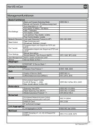
Ha-VIS Middleware . ....................................... 115<br />
Ha-VIS RF-R200 Reader ................................... 117<br />
Ha-VIS mCon 3000 Next Generation .......................... 120<br />
Ha-VIS mCon 3000 Next Generation . . . . . . . . . . . . . . . . . . . . . . . 122<br />
Ha-VIS mCon 3080-A ................................... 125<br />
Ha-VIS mCon 3102-AASFP .............................. 126<br />
Ha-VIS Accessories - Memory Cards ....................... 127<br />
Ha-VIS SFP Modules ................................... 128<br />
7
<strong>HARTING</strong> <strong>News</strong><br />
Contents<br />
Page<br />
Device Connectivity<br />
DIN 41612 connectors<br />
Technical characteristics for types 3Q and 3R ................ 131<br />
Male connectors of complementary type 3Q ................. 132<br />
Male connectors of complementary type 3R. ................. 134<br />
Shrouds for type F ..................................... 136<br />
series<br />
Hoods for bellows male connectors ........................ 137<br />
series<br />
Technical characteristics. ................................ 138<br />
Male and female connectors. ............................. 139<br />
D-Sub series<br />
Turned crimp contacts .................................. 140<br />
Technical characteristics for D-Sub SMT<br />
with straight solder terminations ........................... 141<br />
D-Sub SMT connectors with straight solder terminations. ....... 142<br />
D-Sub SMT connectors<br />
with straight solder terminations and grounding pins ........... 144<br />
Cables<br />
Flat cables for insulation displacement termination,<br />
types SEK and D-Sub. .................................. 146<br />
Ha-VIS data bus cables ................................. 147<br />
PRORFINET cables .................................... 150<br />
Han ® SFP fibre optic cables and accessories ................ 152<br />
Ha-VIS preLink ®<br />
preLink ® Extender and terminal module ..................... 154<br />
8<br />
<strong>HARTING</strong> RJ Industrial ®<br />
RJ45 jacks with transformer . . . . . . . . . . . . . . . . . . . . . . . . . . . . . . 155
<strong>HARTING</strong> <strong>News</strong><br />
Contents<br />
Page<br />
Circular connectors<br />
har-speed adapter M12 - RJ45 and Gender changer. .......... 156<br />
har-speed with slim design ............................... 157<br />
har-flexicon ® series<br />
Pitches 1.27 mm / 2.54 mm<br />
PCB connectors female with IDC termination ............. 158<br />
PCB terminal blocks with push-in-spring-cage termination ... 160<br />
PCB connectors female with push-in-spring-cage termination 162<br />
PCB connectors male ............................... 164<br />
Pitches 3.50 mm / 3.81 mm<br />
PCB terminal blocks with push-in-spring-cage termination ... 166<br />
PCB terminal blocks with screw termination .............. 168<br />
PCB connectors female with push-in-spring-cage termination 170<br />
PCB connectors female with screw termination. ........... 172<br />
PCB connectors male ............................... 174<br />
Pitches 5.00 mm / 5.08 mm<br />
PCB terminal blocks with push-in-spring-cage termination ... 176<br />
PCB terminal blocks with screw termination .............. 178<br />
PCB connectors female with push-in-spring-cage termination 182<br />
PCB connectors female with screw termination. ........... 184<br />
PCB connectors male ............................... 186<br />
<strong>HARTING</strong> eCatalogue ......................................... 188<br />
Addresses . . . . . . . . . . . . . . . . . . . . . . . . . . . . . . . . . . . . . . . . . . . . . . . . . . 189<br />
9
10<br />
Notes
Han ® High Temp<br />
Description<br />
Han ® High Temp is a new product series that is based on our well-established Han ® B and Han ® E series.<br />
We used high-quality materials with wide temperature ranges to produce connectors that are uniquely suited<br />
for a wide variety of applications.<br />
These connectors can withstand temperatures up to 200 °C – so they can be used directly in machines and<br />
facilities that would otherwise require cumbersome and complex constructions.<br />
For our users, this delivers direct advantages:<br />
• The electro-mechanical design process is optimized.<br />
Machine parts which are exposed to high temperatures can be designed modularly.<br />
• The work process is optimized<br />
since lower wiring complexity results in reduced maintenance costs.<br />
• The after-sales phase is optimized<br />
because this more service-friendly approach results in less outages and down times.<br />
Design overview<br />
The basic structure of the Han ® High Temp connector consists<br />
of a bulkhead mounted housing and a cable-side hood.<br />
Hoods and housings:<br />
The aluminium die-cast hoods and housings feature a highly<br />
compressed surface with excellent non-stick properties. It<br />
also has a special non-stick coating on the bulkhead-side seal<br />
which allows easy handling without significant sticking.<br />
Inserts:<br />
The Han ® High Temp series features very rugged contact<br />
inserts, which are really the heart of any connector. The LCP<br />
injection-moulded insert delivers outstanding temperature<br />
resistance coupled with excellent mechanical stability.<br />
Contacts:<br />
Our new temperature resistant contacts, for either screw or<br />
crimp terminations, ensure reliable connections with minimal<br />
contact resistance even at extreme temperatures.<br />
Han ® High Temp connectors<br />
remain robust and reliable for their entire lifespan!<br />
11
Han ® High Temp<br />
Features<br />
• Reliable also at extreme temperatures up to<br />
200 °C<br />
• All piece parts (contacts, insert material, hoods<br />
and housings, seals and grounding elements) are<br />
designed in a temperature resistant way<br />
• Developed on the basis of the proven Han ® E series<br />
for 6, 10, 16 or 24 contacts<br />
• Electrical data for 16 A and 400 V<br />
Technical characteristics<br />
Specifications DIN EN 60 664-1<br />
DIN EN 61 984<br />
Inserts<br />
Number of contacts<br />
6, 10, 16, 24 + PE<br />
Electrical data<br />
acc. to EN 61 984 16 A 400 V 6 kV 3<br />
Rated current<br />
16 A<br />
Rated voltage<br />
400 V<br />
Rated impulse voltage 6 kV<br />
Pollution degree 3<br />
Insulation resistance<br />
≥ 10 10 Ω<br />
Material<br />
LCP<br />
Limiting temperatures -40 °C ... +200 °C<br />
Flammability acc. to UL 94 V 0<br />
Mechanical working life<br />
- mating cycles ≥ 500<br />
Current carrying capacity<br />
The current carrying capacity of the connectors is limited by<br />
the thermal load capability of the contact element material including<br />
the connections and the insulating parts. The derating<br />
curve is therefore valid for currents which flow constantly (nonintermittent)<br />
through each contact element of the connector<br />
evenly, without exceeding the allowed maximum temperature.<br />
Measuring and testing techniques according to<br />
DIN EN 60 512-5<br />
Operating current<br />
Contacts<br />
Material<br />
copper alloy<br />
Contact resistance<br />
≤ 1 mΩ<br />
Crimp termination - min. 0.5 mm²/ AWG 20<br />
Crimp termination - max. 2.5 mm²/ AWG 14<br />
Screw termination - min. 0.5 mm²/ AWG 20<br />
Screw termination - max. 2.5 mm²/ AWG 14<br />
Tigtening-/Testing torque 0.5 Nm<br />
Stripping length<br />
7 mm<br />
Hoods/housings<br />
Material<br />
aluminium die cast<br />
Surface<br />
unpainted<br />
Locking element<br />
stainless steel<br />
Hoods/housings seal<br />
FPM, red<br />
Limiting temperatures -40 °C ... +200 °C<br />
Degree of protection acc. to<br />
DIN EN 60 528<br />
for coupled connector IP 65<br />
Ambient temperature<br />
12<br />
1 wire gauge: 2.5 mm²
Han ® High Temp Size 6 B 400 V 16 A<br />
Number of contacts<br />
6 +<br />
Available September <strong>2013</strong><br />
Part number<br />
Identification Male insert (M) Female insert (F) Drawing Dimensions in mm<br />
Screw termination<br />
with wire protection<br />
09 33 806 2601<br />
09 33 806 2701<br />
a = 19.7 mm<br />
b = 34.7 mm<br />
c = 21.0 mm<br />
d = 37.0 mm<br />
1) Distance for contact max. 21 mm<br />
Crimp termination<br />
Crimp contacts<br />
order separately<br />
09 33 806 2602<br />
09 33 806 2702<br />
Contact arrangement<br />
view from<br />
termination side<br />
Panel cut out<br />
Wire gauge<br />
Part number<br />
Identification (mm²) Male contact Female contact Drawing Dimensions in mm<br />
Han ® High Temp contacts<br />
0.5<br />
0.75<br />
1.0<br />
1.5<br />
2.5<br />
09 33 800 6121<br />
09 33 800 6114<br />
09 33 800 6105<br />
09 33 800 6104<br />
09 33 800 6102<br />
09 33 800 6220<br />
09 33 800 6214<br />
09 33 800 6205<br />
09 33 800 6204<br />
09 33 800 6202<br />
Operating contact<br />
Identification<br />
0.5<br />
0.75<br />
1.0<br />
1.5<br />
2.5<br />
Wire gauge<br />
mm²<br />
mm²<br />
mm²<br />
mm²<br />
mm²<br />
AWG 20<br />
AWG 18<br />
AWG 18<br />
AWG 16<br />
AWG 14<br />
* on the back crimp collar<br />
Identification<br />
no groove<br />
1 groove*<br />
1 groove<br />
2 grooves<br />
3 grooves<br />
Stripping<br />
length<br />
7.5 mm<br />
7.5 mm<br />
7.5 mm<br />
7.5 mm<br />
7.5 mm<br />
13
Han ® High Temp Hoods/Housings Size 6 B<br />
Part number<br />
Cable entry<br />
Identification Low construction High construction metric Drawing Dimensions in mm<br />
Hood<br />
side entry<br />
19 62 806 1540<br />
1 x 20<br />
Hood<br />
side entry<br />
19 62 806 0546<br />
19 62 806 0547<br />
1 x 25<br />
1 x 32<br />
Hood<br />
top entry<br />
19 62 806 1440<br />
1 x 20<br />
Hood<br />
top entry<br />
19 62 806 0446<br />
19 62 806 0447<br />
1 x 25<br />
1 x 32<br />
Part number<br />
Cable entry<br />
Identification Low construction High construction metric Drawing Dimensions in mm<br />
Bulkhead mounted housing<br />
09 62 806 0391<br />
Panel cut out<br />
14
Han ® High Temp Size 10 B 400 V 16 A<br />
Number of contacts<br />
10 +<br />
Available September <strong>2013</strong><br />
Part number<br />
Identification Male insert (M) Female insert (F) Drawing Dimensions in mm<br />
Screw termination<br />
with wire protection<br />
09 33 810 2601<br />
09 33 810 2701<br />
a = 19.7 mm<br />
b = 34.7 mm<br />
c = 21.0 mm<br />
d = 37.0 mm<br />
1) Distance for contact max. 21 mm<br />
Crimp termination<br />
Crimp contacts<br />
order separately<br />
09 33 810 2602<br />
09 33 810 2702<br />
Contact arrangement<br />
view from<br />
termination side<br />
Panel cut out<br />
Wire gauge<br />
Part number<br />
Identification (mm²) Male contact Female contact Drawing Dimensions in mm<br />
Han ® High Temp contacts<br />
0.5<br />
0.75<br />
1.0<br />
1.5<br />
2.5<br />
09 33 800 6121<br />
09 33 800 6114<br />
09 33 800 6105<br />
09 33 800 6104<br />
09 33 800 6102<br />
09 33 800 6220<br />
09 33 800 6214<br />
09 33 800 6205<br />
09 33 800 6204<br />
09 33 800 6202<br />
Operating contact<br />
Identification<br />
0.5<br />
0.75<br />
1.0<br />
1.5<br />
2.5<br />
Wire gauge<br />
mm²<br />
mm²<br />
mm²<br />
mm²<br />
mm²<br />
AWG 20<br />
AWG 18<br />
AWG 18<br />
AWG 16<br />
AWG 14<br />
* on the back crimp collar<br />
Identification<br />
no groove<br />
1 groove*<br />
1 groove<br />
2 grooves<br />
3 grooves<br />
Stripping<br />
length<br />
7.5 mm<br />
7.5 mm<br />
7.5 mm<br />
7.5 mm<br />
7.5 mm<br />
15
Han ® High Temp Hoods/Housings Size 10 B<br />
Part number<br />
Cable entry<br />
Identification Low construction High construction metric Drawing Dimensions in mm<br />
Hood<br />
side entry<br />
19 62 810 1520<br />
1 x 20<br />
Hood<br />
side entry<br />
19 62 810 0526<br />
19 62 810 0527<br />
1 x 25<br />
1 x 32<br />
Hood<br />
top entry<br />
19 62 810 1420<br />
19 62 810 1421<br />
1 x 20<br />
1 x 25<br />
Hood<br />
top entry<br />
19 62 810 0426<br />
19 62 810 0427<br />
1 x 25<br />
1 x 32<br />
Part number<br />
Cable entry<br />
Identification Low construction High construction metric Drawing Dimensions in mm<br />
Bulkhead mounted housing<br />
09 62 810 0391<br />
Panel<br />
cut out<br />
16
Han ® High Temp Size 16 B 400 V 16 A<br />
Number of contacts<br />
16 +<br />
Available September <strong>2013</strong><br />
Part number<br />
Identification Male insert (M) Female insert (F) Drawing Dimensions in mm<br />
Screw termination<br />
with wire protection<br />
09 33 816 2601<br />
09 33 816 2701<br />
1) Distance for contact max. 21 mm<br />
a = 19.7 mm<br />
b = 34.7 mm<br />
c = 21.0 mm<br />
d = 37.0 mm<br />
Crimp termination<br />
Crimp contacts<br />
order separately<br />
09 33 816 2602<br />
09 33 816 2702<br />
Contact arrangement<br />
view from<br />
termination side<br />
Panel cut out<br />
Wire gauge<br />
Part number<br />
Identification (mm²) Male contact Female contact Drawing Dimensions in mm<br />
Han ® High Temp contacts<br />
0.5<br />
0.75<br />
1.0<br />
1.5<br />
2.5<br />
09 33 800 6121<br />
09 33 800 6114<br />
09 33 800 6105<br />
09 33 800 6104<br />
09 33 800 6102<br />
09 33 800 6220<br />
09 33 800 6214<br />
09 33 800 6205<br />
09 33 800 6204<br />
09 33 800 6202<br />
Operating contact<br />
Identification<br />
0.5<br />
0.75<br />
1.0<br />
1.5<br />
2.5<br />
Wire gauge<br />
mm²<br />
mm²<br />
mm²<br />
mm²<br />
mm²<br />
AWG 20<br />
AWG 18<br />
AWG 18<br />
AWG 16<br />
AWG 14<br />
* on the back crimp collar<br />
Identification<br />
no groove<br />
1 groove*<br />
1 groove<br />
2 grooves<br />
3 grooves<br />
Stripping<br />
length<br />
7.5 mm<br />
7.5 mm<br />
7.5 mm<br />
7.5 mm<br />
7.5 mm<br />
17
Han ® High Temp Hoods/Housings Size 16 B<br />
Part number<br />
Cable entry<br />
Identification Low construction High construction metric Drawing Dimensions in mm<br />
Hood<br />
side entry<br />
19 62 816 1521<br />
1 x 20<br />
Hood<br />
side entry<br />
19 62 816 0527<br />
1 x 32<br />
Hood<br />
top entry<br />
19 62 816 1421<br />
1 x 25<br />
Hood<br />
top entry<br />
19 62 816 0427<br />
1 x 32<br />
Part number<br />
Cable entry<br />
Identification Low construction High construction metric Drawing Dimensions in mm<br />
Bulkhead mounted housing<br />
09 62 816 0391<br />
Panel<br />
cut out<br />
18
Han ® High Temp Size 24 B 400 V 16 A<br />
Number of contacts<br />
24 +<br />
Available September <strong>2013</strong><br />
Part number<br />
Identification Male insert (M) Female insert (F) Drawing Dimensions in mm<br />
Crimp termination<br />
with wire protection<br />
09 33 824 2601<br />
09 33 824 2701<br />
1) Distance for contact max. 21 mm<br />
a = 19.7 mm<br />
b = 34.7 mm<br />
c = 21.0 mm<br />
d = 37.0 mm<br />
Screw termination<br />
Crimp contacts<br />
order separately<br />
09 33 824 2602<br />
09 33 824 2702<br />
Contact arrangement<br />
view from<br />
termination side<br />
Panel cut out<br />
Wire gauge<br />
Part number<br />
Identification (mm²) Male contact Female contact Drawing Dimensions in mm<br />
Han ® High Temp contacts<br />
0.5<br />
0.75<br />
1.0<br />
1.5<br />
2.5<br />
09 33 800 6121<br />
09 33 800 6114<br />
09 33 800 6105<br />
09 33 800 6104<br />
09 33 800 6102<br />
09 33 800 6220<br />
09 33 800 6214<br />
09 33 800 6205<br />
09 33 800 6204<br />
09 33 800 6202<br />
Operating contact<br />
Identification<br />
0.5<br />
0.75<br />
1.0<br />
1.5<br />
2.5<br />
Wire gauge<br />
mm²<br />
mm²<br />
mm²<br />
mm²<br />
mm²<br />
AWG 20<br />
AWG 18<br />
AWG 18<br />
AWG 16<br />
AWG 14<br />
* on the back crimp collar<br />
Identification<br />
no groove<br />
1 groove*<br />
1 groove<br />
2 grooves<br />
3 grooves<br />
Stripping<br />
length<br />
7.5 mm<br />
7.5 mm<br />
7.5 mm<br />
7.5 mm<br />
7.5 mm<br />
19
Han ® High Temp Hoods/Housings Size 24 B<br />
Part number<br />
Cable entry<br />
Identification Low construction High construction metric Drawing Dimensions in mm<br />
Hood<br />
side entry<br />
19 62 824 1521<br />
1 x 25<br />
Hood<br />
side entry<br />
19 62 824 0527<br />
19 62 824 0528<br />
1 x 32<br />
1 x 40<br />
Hood<br />
top entry<br />
19 62 824 1422<br />
1 x 32<br />
Hood<br />
top entry<br />
19 62 824 0427<br />
1 x 32<br />
Part number<br />
Cable entry<br />
Identification Low construction High construction metric Drawing Dimensions in mm<br />
Bulkhead mounted housing<br />
09 62 824 0391<br />
Panel<br />
cut out<br />
20
Han ® Standard Hood<br />
Features<br />
• High construction<br />
• Large cabling space<br />
• Cable entry with optimised 30° angle<br />
• Compatible to all standard hoods and housings<br />
Technical characteristics<br />
Material hood/housing<br />
aluminium die cast<br />
Colour<br />
RAL 7037 (grey)<br />
Surface<br />
powder coated<br />
Locking lever Han-Easy Lock ®<br />
Material Locking lever<br />
stainless steel<br />
Seal hood/housing<br />
NBR<br />
Limiting temperatures -40 °C ... +125 °C<br />
Approval acc. to UL 50<br />
in locked position IP 65<br />
21
Han ® Standard Hood<br />
Han ® 16 B hood with M50 cable entry<br />
Identification Part-Number M Drawing Dimensions in mm<br />
Hood<br />
side entry M40<br />
with 2 locking levers on the<br />
bulkhead mounted housing<br />
19 30 016 0523<br />
40<br />
Hood<br />
side entry M50<br />
with 2 locking levers on the<br />
bulkhead mounted housing<br />
19 30 016 0529<br />
50<br />
22
Han ® B Housings, bulkhead mounting, IP 67<br />
Available Juli <strong>2013</strong><br />
Features<br />
• Compatible to all standard hoods/housings<br />
• Approved lever locking system with Han-Easy<br />
Lock ®<br />
• Standard panel cut out<br />
• Degree of protection IP 66 and IP 67<br />
• No sliding off the seal due to the protective flange<br />
Technical Characteristics<br />
Han ® Standard Hoods/Housings<br />
Metal hoods/housings for industrial applications<br />
Material<br />
aluminium die-cast<br />
Colour<br />
RAL 7037 (grey)<br />
Surface<br />
powder-coated<br />
Locking element<br />
Stainless steel<br />
Lever type Han-Easy Lock ®<br />
Hoods/Housings seal NBR<br />
Limiting temperatures -40 °C ... +125 °C<br />
Degree of protection acc.<br />
to DIN EN 60 529<br />
for coupled connector IP 66 and IP 67<br />
23
Han ® B Housings, bulkhead mounting, IP 67<br />
Identification Part-Number Drawing Dimensions in mm<br />
Housings, bulkhead<br />
mounting 6 B<br />
09 30 006 1301<br />
Housings, bulkhead<br />
mounting 10 B<br />
09 30 010 1301<br />
Housings, bulkhead<br />
mounting 16 B<br />
09 30 016 1301<br />
Housings, bulkhead<br />
mounting 24 B<br />
09 30 024 1301<br />
24
Notes<br />
25
Han ® HMC Connectors for High Mating Cycles<br />
Features<br />
This series Han ® HMC (High Mating Cycles) is a connector series specifically aiming at<br />
industrial applications for 10,000 mating cycles.<br />
Benefits:<br />
• High mechanical robustness<br />
• Simple and easy understandable design<br />
• Optimized concept for signal and power transmission<br />
• Low mating and unmating forces<br />
• High contact density<br />
General Description<br />
Han ® B HMC hoods with high<br />
performance locking pin<br />
Ground contacts of crimp inserts<br />
with long lasting HMC contact<br />
spring<br />
Han D ® and Han E ® crimp<br />
contacts with specific HMC gold<br />
coating and a constant contact<br />
force<br />
Han ® B housings with Han-<br />
Easy Lock ® HMC locking lever<br />
26
Han D ® HMC<br />
Technical characteristics<br />
Hoods/Housings Han B ® HMC<br />
Material<br />
aluminium die-cast<br />
Surface<br />
powder coated<br />
RAL 7037 (grey)<br />
Locking element<br />
Han-Easy Lock ® HMC<br />
Flammability acc. to UL 94 V 0<br />
Hoods/Housings seal<br />
NBR<br />
Limiting temperatures -40 °C ... +125 °C<br />
Degree of protection acc. to DIN EN 60 529<br />
for coupled connector IP 65<br />
Features<br />
• High density contacts / connector<br />
• For requirements up to 250 V / 10 A<br />
• Time saving rapid termination by use of crimping<br />
contacts<br />
• Suitable for hoods/housings of series Han ® B<br />
HMC<br />
• Han D ® HMC contacts available with special<br />
HMC gold plating for 10,000 mating cycles<br />
Selection of hoods housings see page 53<br />
Specifications DIN EN 175 301-801<br />
DIN EN 60 664-1<br />
DIN EN 61 984<br />
Inserts<br />
Number of contacts<br />
40, 64 + PE<br />
Electrical data<br />
acc. to EN 61 984 10 A 250 V 4 kV 3<br />
Rated current<br />
10 A<br />
Rated voltage<br />
250 V<br />
Rated impulse voltage<br />
4 kV<br />
Pollution degree 3<br />
Pollution degree 2 also 10 A 230/400 V 4 kV 2<br />
– for wrap terminal only 10 A 250 V 4 kV 2<br />
Rated voltage<br />
acc. to UL/CSA<br />
600 V<br />
Insulation resistance<br />
≥ 10 10 Ω<br />
Material<br />
polycarbonate<br />
Limiting temperatures -40 °C ... +125 °C<br />
Flammability acc. to UL 94 V 0<br />
Mechanical working life<br />
- mating cycles ≥ 10,000<br />
Contacts Han D ® HMC<br />
Material<br />
copper alloy<br />
Surface<br />
HMC gold plating<br />
Contact resistance<br />
≤ 3 mΩ<br />
Crimp terminal - min 0.14 mm² / AWG 26<br />
Crimp terminal - max 2.5 mm² / AWG 14<br />
27
Han D ® HMC<br />
Technical characteristics<br />
Current carrying capacity<br />
The current carrying capacity of the connectors is limited by the thermal load capability of the contact element material including the<br />
connections and the insulating parts. The derating curve is therefore valid for currents which flow constantly (non-intermittent) through<br />
each contact element of the connector evenly, without exceeding the allowed maximum temperature.<br />
Measuring and testing techniques according to DIN EN 60 512-5<br />
Han ® 40 D HMC<br />
Han ® 64 D HMC<br />
Operating current<br />
Operating current<br />
Ambient temperature<br />
Ambient temperature<br />
1 0.75 mm²<br />
2 1.5 mm²<br />
Wire gauge<br />
Part number<br />
Identification (mm²) Male contact Female contact Drawing Dimensions in mm<br />
Crimp contacts<br />
HMC gold plated<br />
0.14-0.37<br />
0.5<br />
0.75<br />
1<br />
1.5<br />
2.5<br />
09 15 200 6124<br />
09 15 200 6123<br />
09 15 200 6125<br />
09 15 200 6122<br />
09 15 200 6121<br />
09 15 200 6126<br />
09 15 200 6224<br />
09 15 200 6223<br />
09 15 200 6225<br />
09 15 200 6222<br />
09 15 200 6221<br />
09 15 200 6226<br />
Wire gauge<br />
D<br />
Stripping<br />
length<br />
0.14-0.37<br />
0.5<br />
0.75<br />
1<br />
1.5<br />
2.5<br />
mm²<br />
mm²<br />
mm²<br />
mm²<br />
mm²<br />
mm²<br />
AWG 26-22<br />
AWG 20<br />
AWG 18<br />
AWG 18<br />
AWG 16<br />
AWG 14<br />
0.9 mm<br />
1.1 mm<br />
1.3 mm<br />
1.45 mm<br />
1.75 mm<br />
2.25 mm<br />
8 mm<br />
8 mm<br />
8 mm<br />
8 mm<br />
8 mm<br />
6 mm<br />
28
Han DD ® HMC<br />
Technical characteristics<br />
Hoods/Housings Han ® B HMC<br />
Material<br />
aluminium die-cast<br />
Surface<br />
powder coated<br />
RAL 7037 (grey)<br />
Locking element<br />
Han-Easy Lock ® , HMC<br />
Flammability acc. to UL 94 V 0<br />
Hoods/Housings seal<br />
NBR<br />
Limiting temperatures -40 °C / 125 °C<br />
Degree of protection<br />
acc. to DIN EN 60 529<br />
for coupled connector IP 65<br />
Features<br />
• High density of crimping contacts, up to 108<br />
contacts/connector<br />
• Time saving rapid termination by use of<br />
crimping contacts<br />
• For requirements up to 250 V / 10 A<br />
• Han D ® HMC contacts available with special<br />
HMC gold plating for 10,000 mating cycles<br />
• Suitable for hoods/housings of series<br />
Han ® B HMC<br />
Selection of hoods housings see page 53<br />
Specifications DIN EN 60 664-1<br />
DIN EN 61 984<br />
Inserts<br />
Number of contacts<br />
24, 42, 72, 108, + PE<br />
Electrical data<br />
acc. to EN 61 984 10 A 250 V 4 kV 3<br />
Rated current<br />
10 A<br />
Rated voltage<br />
250 V<br />
Rated impulse voltage<br />
4 kV<br />
Pollution degree 3<br />
Pollution degree 2 also 10 A 230/400 V 4 kV 2<br />
Rated voltage<br />
acc. to UL/CSA<br />
600 V<br />
Insulation resistance<br />
≥ 10 10 Ω<br />
Material<br />
polycarbonate<br />
Limiting temperatures -40 °C ... +125 °C<br />
Flammability acc. to UL 94 V 0<br />
Mechanical working life<br />
- mating cycles ≥ 10,000<br />
Contacts Han D ® HMC<br />
Material<br />
copper alloy<br />
Surface - hard-gold plated HMC gold plated<br />
Contact resistance<br />
≤ 3 mΩ<br />
Crimp terminal - min 0.14 mm² / AWG 26<br />
Crimp terminal - max 2.5 mm² / AWG 14<br />
29
Han DD ® HMC<br />
Technical characteristics<br />
Current carrying capacity<br />
The current carrying capacity of the connectors is limited by the thermal load capability of the contact element material including the<br />
connections and the insulating parts. The derating curve is therefore valid for currents which flow constantly (non-intermittent) through<br />
each contact element of the connector evenly, without exceeding the allowed maximum temperature.<br />
Measuring and testing techniques according to DIN EN 60 512-5<br />
Operating current<br />
Ambient temperature<br />
Operating current<br />
Ambient temperature<br />
➀ Han ® 24 DD HMC<br />
➁ Han ® 42 DD HMC<br />
➂ Han ® 72 DD HMC<br />
➃ Han ® 108 DD HMC<br />
Wire gauge<br />
Part number<br />
Identification (mm²) Male contact Female contact Drawing Dimensions in mm<br />
Crimp contacts<br />
HMC gold plated<br />
0.14-0.37<br />
0.5<br />
0.75<br />
1<br />
1.5<br />
2.5<br />
09 15 200 6124<br />
09 15 200 6123<br />
09 15 200 6125<br />
09 15 200 6122<br />
09 15 200 6121<br />
09 15 200 6126<br />
09 15 200 6224<br />
09 15 200 6223<br />
09 15 200 6225<br />
09 15 200 6222<br />
09 15 200 6221<br />
09 15 200 6226<br />
Wire gauge<br />
D<br />
Stripping<br />
length<br />
0.14-0.37<br />
0.5<br />
0.75<br />
1<br />
1.5<br />
2.5<br />
mm²<br />
mm²<br />
mm²<br />
mm²<br />
mm²<br />
mm²<br />
AWG 26-22<br />
AWG 20<br />
AWG 18<br />
AWG 18<br />
AWG 16<br />
AWG 14<br />
0.9 mm<br />
1.1 mm<br />
1.3 mm<br />
1.45 mm<br />
1.75 mm<br />
2.25 mm<br />
8 mm<br />
8 mm<br />
8 mm<br />
8 mm<br />
8 mm<br />
6 mm<br />
30
Han ® 24 DD HMC Size 6 B 250 V 10 A<br />
Number of contacts<br />
24 +<br />
Inserts<br />
Available May <strong>2013</strong><br />
Part number<br />
Identification Series Male insert (M) Female insert (F) Drawing Dimensions in mm<br />
Crimp terminal<br />
Order crimp contacts<br />
separately (see<br />
Technical characteristics<br />
on page 19)<br />
Han<br />
DD ®<br />
HMC<br />
09 16 224 3001 09 16 224 3101<br />
Only with Han Docking<br />
Frame (see page 61)<br />
1) Distance for contact max. 21 mm<br />
Contact arrangement<br />
view from termination side<br />
Panel cut out for inserts<br />
for use without hoods/housings<br />
Coding pin<br />
Coding pin<br />
09 33 000 9915<br />
Use of the coding pin prevents incorrect mating to<br />
other connectors of the same type. The male pin<br />
should be omitted from the opposing cavity in the<br />
male insert.<br />
31
Han ® 42 DD HMC Size 10 B 250 V 10 A<br />
Number of contacts<br />
42 +<br />
Inserts<br />
Available May <strong>2013</strong><br />
Part number<br />
Identification Series Male insert (M) Female insert (F) Drawing Dimensions in mm<br />
Crimp terminal<br />
Order crimp contacts<br />
separately (see<br />
Technical characteristics<br />
on page 19)<br />
Han<br />
DD ®<br />
HMC<br />
09 16 242 3001 09 16 242 3101<br />
1) Distance for contact max. 21 mm<br />
Contact arrangement<br />
view from termination side<br />
Panel cut out for inserts<br />
for use without hoods/housings<br />
Coding pin<br />
Coding pin<br />
09 33 000 9915<br />
Use of the coding pin prevents incorrect mating to<br />
other connectors of the same type. The male pin<br />
should be omitted from the opposing cavity in the<br />
male insert.<br />
32
Han ® 40 D HMC Size 16 B 250 V 10 A<br />
Number of contacts<br />
40 +<br />
Inserts<br />
Available May <strong>2013</strong><br />
Part number<br />
Identification Series Male insert (M) Female insert (F) Drawing Dimensions in mm<br />
Crimp terminal<br />
Order crimp contacts<br />
separately (see<br />
Technical characteristics<br />
on page 17)<br />
Han<br />
D ®<br />
HMC<br />
09 21 240 3001 09 21 240 3101<br />
1) Distance for contact max. 21 mm<br />
Contact arrangement<br />
view from termination side<br />
Panel cut out for inserts<br />
for use without hoods/housings<br />
Coding pin<br />
Coding pin<br />
09 33 000 9915<br />
Use of the coding pin prevents incorrect mating to<br />
other connectors of the same type. The male pin<br />
should be omitted from the opposing cavity in the<br />
male insert.<br />
33
Han ® 72 DD HMC Size 16 B 250 V 10 A<br />
Number of contacts<br />
72 +<br />
Inserts<br />
Available May <strong>2013</strong><br />
Part number<br />
Identification Series Male insert (M) Female insert (F) Drawing Dimensions in mm<br />
Crimp terminal<br />
Order crimp contacts<br />
separately (see<br />
Technical characteristics<br />
on page 19)<br />
Han<br />
DD ®<br />
HMC<br />
09 16 272 3001 09 16 272 3101<br />
1) Distance for contact max. 21 mm<br />
Contact arrangement<br />
view from termination side<br />
Panel cut out for inserts<br />
for use without hoods/housings<br />
Coding pin<br />
Coding pin<br />
09 33 000 9915<br />
Use of the coding pin prevents incorrect mating to<br />
other connectors of the same type. The male pin<br />
should be omitted from the opposing cavity in the<br />
male insert.<br />
34
Han ® 64 D HMC Size 24 B 250 V 10 A<br />
Number of contacts<br />
64 +<br />
Inserts<br />
Available May <strong>2013</strong><br />
Part number<br />
Identification Series Male insert (M) Female insert (F) Drawing Dimensions in mm<br />
Crimp terminal<br />
Order crimp contacts<br />
separately (see<br />
Technical characteristics<br />
on page 17)<br />
Han<br />
D ®<br />
HMC<br />
09 21 264 3001 09 21 264 3101<br />
1) Distance for contact max. 21 mm<br />
Contact arrangement<br />
view from termination side<br />
Panel cut out for inserts<br />
for use without hoods/housings<br />
Coding pin<br />
Coding pin<br />
09 33 000 9915<br />
Use of the coding pin prevents incorrect mating to<br />
other connectors of the same type. The male pin<br />
should be omitted from the opposing cavity in the<br />
male insert.<br />
35
Han ® 108 DD HMC Size 24 B 250 V 10 A<br />
Number of contacts<br />
108 +<br />
Inserts<br />
Available May <strong>2013</strong><br />
Part number<br />
Identification Series Male insert (M) Female insert (F) Drawing Dimensions in mm<br />
Crimp terminal<br />
Order crimp contacts<br />
separately (see<br />
Technical characteristics<br />
on page 19)<br />
Han<br />
DD ®<br />
HMC<br />
09 16 208 3001 09 16 208 3101<br />
1) Distance for contact max. 21 mm<br />
Contact arrangement<br />
view from termination side<br />
Panel cut out for inserts<br />
for use without hoods/housings<br />
Coding pin<br />
Coding pin<br />
09 33 000 9915<br />
Use of the coding pin prevents incorrect mating to<br />
other connectors of the same type. The male pin<br />
should be omitted from the opposing cavity in the<br />
male insert.<br />
36
Han E ® HMC<br />
Technical characteristics<br />
Hoods/Housings Han ® B HMC<br />
Material<br />
aluminium die-cast<br />
Surface<br />
powder-coated<br />
Locking element<br />
Han-Easy Lock ® HMC<br />
Flammability acc. to UL 94 V 0<br />
Hoods/Housings seal<br />
NBR<br />
Limiting temperatures -40 °C ... +125 °C<br />
Degree of protection<br />
acc. to DIN EN 60 529<br />
for coupled connector IP 65<br />
Features<br />
• Han E ® HMC contacts with crimp termination<br />
• Suitable for hoods/housings of series<br />
Han ® B HMC<br />
• Han E ® HMC contacts available with special<br />
HMC gold plating for 10,000 mating cycles<br />
selection of hoods/housings see page 53<br />
Specifications DIN EN 60 664-1<br />
DIN EN 61 984<br />
Inserts<br />
Number of contacts<br />
6, 10, 16, 24, + PE<br />
Electrical data<br />
acc. to EN 61 984 16 A 500 V 6 kV 3<br />
Rated current<br />
16 A<br />
Rated voltage<br />
500 V<br />
Rated impulse voltage<br />
6 kV<br />
Pollution degree 3<br />
Pollution degree 2 also 16 A 400/690 V 6 kV 2<br />
Rated voltage<br />
acc. to UL/CSA<br />
600 V<br />
Insulation resistance<br />
≥ 10 10 Ω<br />
Material<br />
polycarbonate<br />
Limiting temperatures -40 °C ... +125 °C<br />
Flammability acc. to UL 94 V 0<br />
Mechanical working life<br />
- mating cycles ≥ 10,000<br />
Contacts Han E ® HMC<br />
Material<br />
copper alloy<br />
Surface<br />
HMC gold plated<br />
Contact resistance<br />
≤ 1 mΩ<br />
Crimp terminal - min 0.14 mm² / AWG 26<br />
Crimp terminal - max 4 mm² / AWG 12<br />
37
Han E ® HMC<br />
Technical characteristics<br />
Current carrying capacity<br />
The current carrying capacity of the connectors is limited by the thermal load capability of the contact element material including the<br />
connections and the insulating parts. The derating curve is therefore valid for currents which flow constantly (non-intermittent) through<br />
each contact element of the connector evenly, without exceeding the allowed maximum temperature.<br />
Measuring and testing techniques according to DIN EN 60 512-5<br />
Operating current<br />
Ambient temperature<br />
Operating current<br />
Ambient temperature<br />
➀ Han ® 6 E HMC<br />
➁ Han ® 10 E HMC<br />
➂ Han ® 16 E HMC<br />
➃ Han ® 24 E HMC<br />
Wire gauge<br />
Part number<br />
Identification (mm²) Male contact Female contact Drawing Dimensions in mm<br />
Crimp contacts<br />
HMC gold plated<br />
Operating contact<br />
Identification<br />
0.14-0.37<br />
0.5<br />
0.75<br />
1<br />
1.5<br />
2.5<br />
4<br />
09 33 200 6117<br />
09 33 200 6122<br />
09 33 200 6115<br />
09 33 200 6118<br />
09 33 200 6116<br />
09 33 200 6123<br />
09 33 200 6119<br />
09 33 200 6217<br />
09 33 200 6222<br />
09 33 200 6215<br />
09 33 200 6218<br />
09 33 200 6216<br />
09 33 200 6223<br />
09 33 200 6221<br />
Identification<br />
no groove<br />
no groove<br />
1 groove*<br />
1 groove<br />
2 grooves<br />
3 grooves<br />
wide groove<br />
no groove<br />
Wire gauge<br />
0.14-0.37 mm²<br />
0.5 mm²<br />
0.75 mm²<br />
1 mm²<br />
1.5 mm²<br />
2.5 mm²<br />
3 mm²<br />
4 mm²<br />
AWG 26-22<br />
AWG 20<br />
AWG 18<br />
AWG 18<br />
AWG 16<br />
AWG 14<br />
AWG 12<br />
AWG 12<br />
Stripping<br />
length<br />
7.5 mm<br />
7.5 mm<br />
7.5 mm<br />
7.5 mm<br />
7.5 mm<br />
7.5 mm<br />
7.5 mm<br />
7.5 mm<br />
* on the back crimp collar<br />
38<br />
Coding pin<br />
for crimp inserts only<br />
09 33 000 9954<br />
Crimp contacts 0.14 ... 0.37 mm² only used with BUCHANAN crimping tool 09 99 000 0001<br />
Use of the coding pin prevents<br />
incorrect mating to other connectors<br />
of the same type. The<br />
male pin should be omitted from<br />
the opposing cavity in the male<br />
insert.
Han ® EEE HMC<br />
Technical characteristics<br />
Hoods/Housings Han ® B HMC<br />
Material<br />
aluminium die-cast<br />
Surface<br />
powder-coated<br />
Locking element<br />
Han-Easy Lock ® HMC<br />
Flammability acc. to UL 94 V 0<br />
Hoods/Housings seal<br />
NBR<br />
Limiting temperatures -40 °C ... +125 °C<br />
Degree of protection<br />
acc. to DIN EN 60 529<br />
for coupled connector IP 65<br />
Features<br />
• Han E ® HMC contacts with crimp termination<br />
• Polarised insert<br />
• Suitable for hoods/housings of series<br />
Han ® B HMC<br />
• Han E ® HMC contacts available with special<br />
HMC gold plating for 10,000 mating cycles<br />
Selection of hoods/housings see page 53<br />
Specifications DIN EN 60 664-1<br />
DIN EN 61 984<br />
Inserts<br />
Number of contacts<br />
40, 64 + PE<br />
Electrical data<br />
acc. to EN 61 984 16 A 500 V 6 kV 3<br />
Rated current<br />
16 A<br />
Rated voltage<br />
500 V<br />
Rated impulse voltage<br />
6 kV<br />
Pollution degree 3<br />
Insulation resistance<br />
≥ 10 10 Ω<br />
Material<br />
polycarbonate<br />
Limiting temperatures -40 °C ... +125 °C<br />
Flammability acc. to UL 94 V 0<br />
Mechanical working life<br />
- mating cycles ≥ 10,000<br />
Contacts Han ® E HMC<br />
Material<br />
copper alloy<br />
Surface<br />
HMC gold plated<br />
Contact resistance<br />
≤ 1 mΩ<br />
Crimp terminal - min 0.14 mm² / AWG 26<br />
Crimp terminal - max 4 mm² / AWG 12<br />
39
Han ® EEE HMC<br />
Technical characteristics<br />
Current carrying capacity<br />
The current carrying capacity of the connectors is limited by the thermal load capability of the contact element material including the<br />
connections and the insulating parts. The derating curve is therefore valid for currents which flow constantly (non-intermittent) through<br />
each contact element of the connector evenly, without exceeding the allowed maximum temperature.<br />
Measuring and testing techniques according to DIN EN 60 512-5<br />
Operating current<br />
Ambient temperature<br />
➀ Han ® 64 EEE HMC / 1.5 mm²<br />
➁ Han ® 64 EEE HMC / 2.5 mm²<br />
➂ Han ® 64 EEE HMC / 4.0 mm²<br />
➃ Han ® 40 EEE HMC / 1.5 mm²<br />
➄ Han ® 40 EEE HMC / 2.5 mm²<br />
Wire gauge<br />
Part number<br />
Identification (mm²) Male contact Female contact Drawing Dimensions in mm<br />
Operating contact<br />
Identification<br />
Crimp contacts<br />
HMC gold plated<br />
0.14-0.37<br />
0.5<br />
0.75<br />
1<br />
1.5<br />
2.5<br />
4<br />
09 33 200 6117<br />
09 33 200 6122<br />
09 33 200 6115<br />
09 33 200 6118<br />
09 33 200 6116<br />
09 33 200 6123<br />
09 33 200 6119<br />
09 33 200 6217<br />
09 33 200 6222<br />
09 33 200 6215<br />
09 33 200 6218<br />
09 33 200 6216<br />
09 33 200 6223<br />
09 33 200 6221<br />
Identification<br />
no groove<br />
no groove<br />
1 groove*<br />
1 groove<br />
2 grooves<br />
3 grooves<br />
wide groove<br />
no groove<br />
Wire gauge<br />
0.14-0.37 mm²<br />
0.5 mm²<br />
0.75 mm²<br />
1 mm²<br />
1.5 mm²<br />
2.5 mm²<br />
3 mm²<br />
4 mm²<br />
AWG 26-22<br />
AWG 20<br />
AWG 18<br />
AWG 18<br />
AWG 16<br />
AWG 14<br />
AWG 12<br />
AWG 12<br />
Stripping<br />
length<br />
7.5 mm<br />
7.5 mm<br />
7.5 mm<br />
7.5 mm<br />
7.5 mm<br />
7.5 mm<br />
7.5 mm<br />
7.5 mm<br />
* on the back crimp collar<br />
40<br />
Coding pin<br />
for crimp inserts only<br />
09 33 000 9954<br />
Crimp contacts 0.14 ... 0.37 mm² only used with BUCHANAN crimping tool 09 99 000 0001<br />
Use of the coding pin prevents<br />
incorrect mating to other connectors<br />
of the same type. The<br />
male pin should be omitted from<br />
the opposing cavity in the male<br />
insert.
Han ® 6 E HMC Size 6 B 500 V 16 A<br />
Number of contacts<br />
6 +<br />
Inserts<br />
Part number<br />
Identification Series Male insert (M) Female insert (F) Drawing Dimensions in mm<br />
Crimp terminal<br />
Order crimp contacts<br />
separately (see<br />
Technical characteristics<br />
on page 27)<br />
Han E ®<br />
HMC<br />
09 33 206 2602 09 33 206 2702<br />
1) Distance for contact max. 21 mm<br />
Only with Han ® Docking<br />
frame (page 61)<br />
a b c d<br />
Han E ® HMC 19 34 19 36<br />
Contact arrangement<br />
view from termination side<br />
41
Han ® 10 E HMC Size 10 B 500 V 16 A<br />
Number of contacts<br />
10 +<br />
Inserts<br />
Part number<br />
Identification Series Male insert (M) Female insert (F) Drawing Dimensions in mm<br />
Crimp terminal<br />
Order crimp contacts<br />
separately (see<br />
Technical characteristics<br />
on page 27)<br />
Han E ®<br />
HMC<br />
09 33 210 2602 09 33 210 2702<br />
1) Distance for contact max. 21 mm<br />
a b c d<br />
Han E ® HMC 19 34 19 36<br />
Contact arrangement<br />
view from termination side<br />
Panel cut out<br />
42
Han ® 16 E HMC Size 16 B 500 V 16 A<br />
Number of contacts<br />
16 +<br />
Inserts<br />
Part number<br />
Identification Series Male insert (M) Female insert (F) Drawing Dimensions in mm<br />
Crimp terminal<br />
Order crimp contacts<br />
separately (see<br />
Technical characteristics<br />
on page 27)<br />
Han E ®<br />
HMC<br />
09 33 216 2602 09 33 216 2702<br />
1) Distance for contact max. 21 mm<br />
a b c d<br />
Han E ® HMC 19 34 19 36<br />
Contact arrangement<br />
view from termination side<br />
Panel cut out<br />
43
Han ® 40 EEE HMC Size 16 B 500 V 16 A<br />
Number of contacts<br />
40 +<br />
Inserts<br />
Part number<br />
Identification Series Male insert (M) Female insert (F) Drawing Dimensions in mm<br />
Crimp termination<br />
Order crimp contacts<br />
separately (see<br />
Technical characteristics<br />
on page 29)<br />
Han ®<br />
EEE<br />
HMC<br />
09 32 240 3001 09 32 240 3101<br />
1) Distance for contact max. 21 mm<br />
Contact arrangement<br />
view from termination side<br />
Panel cut out<br />
44
Han ® 24 E HMC Size 24 B 500 V 16 A<br />
Number of contacts<br />
24 +<br />
Inserts<br />
Part number<br />
Identification Series Male insert (M) Female insert (F) Drawing Dimensions in mm<br />
Crimp terminal<br />
Order crimp contacts<br />
separately (see<br />
Technical characteristics<br />
on page 27)<br />
Han E ®<br />
HMC<br />
09 33 224 2602 09 33 224 2702<br />
1) Distance for contact max. 21 mm<br />
a b c d<br />
Han E ® HMC 19 34 19 36<br />
Contact arrangement<br />
view from termination side<br />
Panel cut out<br />
45
Han ® 64 EEE HMC Size 24 B 500 V 16 A<br />
Number of contacts<br />
64 +<br />
Inserts<br />
Part number<br />
Identification Series Male insert (M) Female insert (F) Drawing Dimensions in mm<br />
Crimp termination<br />
Order crimp contacts<br />
separately (see<br />
Technical characteristics<br />
on page 29)<br />
Han ®<br />
EEE<br />
HMC<br />
09 32 264 3001 09 32 264 3101<br />
1) Distance for contact max. 21 mm<br />
Contact arrangement<br />
view from termination side<br />
Panel cut out<br />
46
Summary Han-Modular ®<br />
Series Han E ® module Han ® EE module Han E ® Protected module Han ® EEE module<br />
Number of contacts 6 8 6 20<br />
Modules<br />
Crimp terminal<br />
Crimp terminal<br />
Crimp terminal<br />
Crimp terminal<br />
Rated current<br />
Rated voltage<br />
Wire gauge<br />
Page<br />
16 A<br />
500 V<br />
0.14 … 4 mm²<br />
36<br />
16 A<br />
400 V<br />
0.14 … 4 mm²<br />
38<br />
16 A<br />
830 V<br />
0.14 … 4 mm²<br />
40<br />
16 A<br />
500 V<br />
0.14 … 4 mm²<br />
42<br />
Series Han DD ® module Han ® DDD module<br />
Number of contacts 12 17<br />
Modules<br />
Crimp terminal<br />
Crimp terminal<br />
Rated current<br />
Rated voltage<br />
Wire gauge<br />
Page<br />
10 A<br />
250 V<br />
0.14 … 2.5 mm²<br />
44<br />
10 A<br />
160 V<br />
0.14 … 2.5 mm²<br />
46<br />
47
Han-Modular ® Docking frame<br />
Features<br />
• Blind mating connector system for drawer systems<br />
• Direct panel mounting without housing<br />
• Very robust design<br />
• Solid pre-leading guid pins and float bushes<br />
• Can be fixed with standard M4 screws<br />
• Designed for 10,000 mating cycles<br />
Notice:<br />
Due the plastic material used in the docking frame<br />
without PE, the panel will need to be grounded<br />
separately<br />
Technical characteristics<br />
Specifications DIN EN 60 664-1<br />
DIN EN 61 984<br />
Docking frames<br />
Number of modules 2, 4, 6<br />
Material<br />
- Docking frames polycarbonate<br />
- Float washer zinc die-cast<br />
Floating tolerance<br />
± 2 mm<br />
Aligning tolerance<br />
± 4 mm<br />
Limiting temperatures -40 °C ... +125 °C<br />
Flammability acc. to UL 94 V 0<br />
Mechanical working life<br />
- mating cycles ≥ 10,000<br />
48
Han-Modular ® Docking frame<br />
Part number<br />
Identification Marking A ... F 1) Marking a ... f 2) Drawing Dimensions in mm<br />
Docking frame for<br />
2 modules<br />
09 14 006 1701<br />
1 floating tolerance ±2 mm<br />
Panel cut out<br />
Docking frame for<br />
2 modules<br />
09 14 006 1711<br />
Panel cut out<br />
Docking frame for<br />
4 modules<br />
09 14 016 1701<br />
1 floating tolerance ±2 mm<br />
Docking frame for<br />
4 modules<br />
09 14 016 1711<br />
Panel cut out<br />
1) Float mount<br />
2) Fixed<br />
49
Han-Modular ® Docking frame<br />
Part number<br />
Identification Marking A ... F 1) Marking a ... f 2) Drawing Dimensions in mm<br />
Docking frame for<br />
6 modules<br />
09 14 024 1701<br />
1 floating tolerance ±2 mm<br />
Docking frame for<br />
6 modules<br />
09 14 024 1711<br />
Panel cut out<br />
Float washer<br />
to enable the<br />
frame to be float<br />
mounted using<br />
standard M4<br />
fixing screws<br />
09 14 000 9936<br />
50<br />
1) Float mount<br />
2) Fixed
Han E ® module<br />
Features<br />
• Suitable for Han E ® HMC crimp contacts<br />
• Standard module for power up to 40 A<br />
• Designed for 10,000 mating cycles with Han E ®<br />
HMC crimp contacts and only with Han-Modular ®<br />
Docking frame<br />
Technical characteristics<br />
Specifications DIN EN 60 664-1<br />
DIN EN 61 984<br />
Approvals ,<br />
Inserts<br />
Number of contacts 6<br />
Electrical data<br />
acc. to EN 61 984 16 A 500 V 6 kV 3<br />
Rated current<br />
16 A<br />
Rated voltage<br />
500 V<br />
Rated impulse voltage<br />
6 kV<br />
Pollution degree 3<br />
Rated voltage<br />
acc. to UL/CSA<br />
600 V<br />
Insulation resistance<br />
≥ 10 10 Ω<br />
Material<br />
polycarbonate<br />
Limiting temperatures -40 °C ... +125 °C<br />
Flammability acc. to UL 94 V 0<br />
Mechanical working life<br />
- mating cycles ≥ 10,000<br />
Current carrying capacity<br />
The current carrying capacity of the connectors is limited by the<br />
thermal load capability of the contact element material including<br />
the connections and the insulating parts. The derating curve<br />
is therefore valid for currents which flow constantly (non-intermittent)<br />
through each contact element of the connector evenly,<br />
without exceeding the allowed maximum temperature.<br />
Measuring and testing techniques according to<br />
DIN EN 60 512-5<br />
Contacts Han E ® HMC<br />
Material<br />
copper alloy<br />
Surface<br />
HMC gold plated<br />
Contact resistance<br />
≤ 1 mΩ<br />
Crimp terminal<br />
- mm² 0.14 ... 4 mm²<br />
- AWG 26 ... 12<br />
Operating current<br />
Ambient temperature<br />
➀ 24 B HMC hoods/housings with 6 modules; wire gauge: 2.5 mm²<br />
➁ 24 B HMC hoods/housings with 6 modules; wire gauge: 1.5 mm²<br />
51
Han E ® module<br />
500 V 16 A<br />
Number of contacts<br />
6<br />
Part number<br />
Identification Male insert (M) Female insert (F) Drawing Dimensions in mm<br />
Crimp terminal<br />
Order crimp contacts<br />
separately<br />
09 14 006 3001 09 14 006 3101<br />
Contact arrangement view from termination side<br />
Wire gauge<br />
Part number<br />
Identification (mm²) Male contact Female contact Drawing Dimensions in mm<br />
Crimp contacts<br />
HMC gold plated<br />
Operating contact<br />
Identification<br />
0.14-0.37<br />
0.5<br />
0.75<br />
1<br />
1.5<br />
2.5<br />
4<br />
09 33 200 6117<br />
09 33 200 6122<br />
09 33 200 6115<br />
09 33 200 6118<br />
09 33 200 6116<br />
09 33 200 6123<br />
09 33 200 6119<br />
09 33 200 6217<br />
09 33 200 6222<br />
09 33 200 6215<br />
09 33 200 6218<br />
09 33 200 6216<br />
09 33 200 6223<br />
09 33 200 6221<br />
Identification<br />
no groove<br />
no groove<br />
1 groove*<br />
1 groove<br />
2 grooves<br />
3 grooves<br />
wide groove<br />
no groove<br />
Wire gauge<br />
0.14-0.37 mm²<br />
0.5 mm²<br />
0.75 mm²<br />
1 mm²<br />
1.5 mm²<br />
2.5 mm²<br />
3 mm²<br />
4 mm²<br />
AWG 26-22<br />
AWG 20<br />
AWG 18<br />
AWG 18<br />
AWG 16<br />
AWG 14<br />
AWG 12<br />
AWG 12<br />
Stripping<br />
length<br />
7.5 mm<br />
7.5 mm<br />
7.5 mm<br />
7.5 mm<br />
7.5 mm<br />
7.5 mm<br />
7.5 mm<br />
7.5 mm<br />
* on the back crimp collar<br />
52<br />
Crimp contacts 0.14 ... 0.37 mm² only used with BUCHANAN crimping tool 09 99 000 0001
Han ® EE module<br />
Features<br />
• Suitable for Han E ® HMC crimp contacts<br />
• High contact density<br />
• Designed for 10,000 mating cycles with Han E ®<br />
HMC crimp contacts and only with Han-Modular ®<br />
Docking frame<br />
Technical characteristics<br />
Specifications DIN EN 60 664-1<br />
DIN EN 61 984<br />
Approvals<br />
Inserts<br />
Number of contacts 8<br />
Electrical data<br />
acc. to EN 61 984 16 A 400 V 6 kV 3<br />
Rated current<br />
16 A<br />
Rated voltage<br />
400 V<br />
Rated impulse voltage<br />
6 kV<br />
Pollution degree 3<br />
Rated voltage<br />
acc. to UL<br />
600 V<br />
Insulation resistance<br />
≥ 10 10 Ω<br />
Material<br />
polycarbonate<br />
Limiting temperatures -40 °C ... +125 °C<br />
Flammability acc. to UL 94 V 0<br />
Mechanical working life<br />
- mating cycles ≥ 10,000<br />
Current carrying capacity<br />
The current carrying capacity of the connectors is limited by the<br />
thermal load capability of the contact element material including<br />
the connections and the insulating parts. The derating curve<br />
is therefore valid for currents which flow constantly (non-intermittent)<br />
through each contact element of the connector evenly,<br />
without exceeding the allowed maximum temperature.<br />
Measuring and testing techniques according to<br />
DIN EN 60 512-5<br />
Contacts Han E ® HMC<br />
Material<br />
copper alloy<br />
Surface<br />
HMC gold plated<br />
Contact resistance<br />
≤ 1 mΩ<br />
Crimp terminal<br />
- mm² 0.14 ... 4 mm²<br />
- AWG 26 ... 12<br />
Operating current<br />
Ambient temperature<br />
➀ 24 B HMC hoods/housings with 6 modules; wire gauge: 2.5 mm²<br />
➁ 24 B HMC hoods/housings with 6 modules; wire gauge: 1.5 mm²<br />
53
Han ® EE module<br />
400 V 16 A<br />
Number of contacts<br />
8<br />
Part number<br />
Identification Male insert (M) Female insert (F) Drawing Dimensions in mm<br />
Crimp terminal<br />
Order crimp contacts<br />
separately<br />
09 14 008 3001 09 14 008 3101<br />
Contact arrangement view from termination side<br />
Wire gauge<br />
Part number<br />
Identification (mm²) Male contact Female contact Drawing Dimensions in mm<br />
Crimp contacts<br />
HMC gold plated<br />
Operating contact<br />
Identification<br />
0.14-0.37<br />
0.5<br />
0.75<br />
1<br />
1.5<br />
2.5<br />
4<br />
09 33 200 6117<br />
09 33 200 6122<br />
09 33 200 6115<br />
09 33 200 6118<br />
09 33 200 6116<br />
09 33 200 6123<br />
09 33 200 6119<br />
09 33 200 6217<br />
09 33 200 6222<br />
09 33 200 6215<br />
09 33 200 6218<br />
09 33 200 6216<br />
09 33 200 6223<br />
09 33 200 6221<br />
Identification<br />
no groove<br />
no groove<br />
1 groove*<br />
1 groove<br />
2 grooves<br />
3 grooves<br />
wide groove<br />
no groove<br />
Wire gauge<br />
0.14-0.37 mm²<br />
0.5 mm²<br />
0.75 mm²<br />
1 mm²<br />
1.5 mm²<br />
2.5 mm²<br />
3 mm²<br />
4 mm²<br />
AWG 26-22<br />
AWG 20<br />
AWG 18<br />
AWG 18<br />
AWG 16<br />
AWG 14<br />
AWG 12<br />
AWG 12<br />
Stripping<br />
length<br />
7.5 mm<br />
7.5 mm<br />
7.5 mm<br />
7.5 mm<br />
7.5 mm<br />
7.5 mm<br />
7.5 mm<br />
7.5 mm<br />
* on the back crimp collar<br />
54<br />
Crimp contacts 0.14 ... 0.37 mm² only used with BUCHANAN crimping tool 09 99 000 0001
Han E ® Protected module<br />
Features<br />
• Suitable for Han E ® HMC crimp contacts<br />
• designed for a high working voltage up to 830 V<br />
• finger safe male and female contacts<br />
• Designed for 10,000 mating cycles with Han E ®<br />
HMC crimp contacts and only with Han-Modular ®<br />
Docking frame<br />
Technical characteristics<br />
Specifications DIN EN 60 664-1<br />
DIN EN 61 984<br />
Approvals<br />
Inserts<br />
Number of contacts 6<br />
Electrical data<br />
acc. to EN 61 984 16 A 830 V 8 kV 3<br />
Rated current<br />
16 A<br />
Rated voltage<br />
830 V<br />
Rated impulse voltage<br />
8 kV<br />
Pollution degree 3<br />
Rated voltage<br />
acc. to UL<br />
600 V<br />
Insulation resistance<br />
≥ 10 10 Ω<br />
Material<br />
polycarbonate<br />
Limiting temperatures -40 °C ... +125 °C<br />
Flammability acc. to UL 94 V 0<br />
Mechanical working life<br />
- mating cycles ≥ 10,000<br />
Current carrying capacity<br />
The current carrying capacity of the connectors is limited by the<br />
thermal load capability of the contact element material including<br />
the connections and the insulating parts. The derating curve<br />
is therefore valid for currents which flow constantly (non-intermittent)<br />
through each contact element of the connector evenly,<br />
without exceeding the allowed maximum temperature.<br />
Measuring and testing techniques according to<br />
DIN EN 60 512-5<br />
Contacts Han E ® HMC<br />
Material<br />
copper alloy<br />
Surface<br />
HMC gold plated<br />
Contact resistance<br />
≤ 1 mΩ<br />
Crimp terminal<br />
- mm² 0.14 ... 4 mm²<br />
- AWG 26 ... 12<br />
Operating current<br />
Ambient temperature<br />
➀ 24 B HMC hoods/housings with 6 modules; wire gauge: 1.5 mm²<br />
➁ 24 B HMC hoods/housings with 6 modules; wire gauge: 2.5 mm²<br />
➂ 24 B HMC hoods/housings with 6 modules; wire gauge: 4 mm²<br />
55
Han E ® Protected module<br />
830 V 16 A<br />
Number of contacts<br />
6<br />
Part number<br />
Identification Male insert (M) Female insert (F) Drawing Dimensions in mm<br />
Crimp terminal<br />
Order crimp contacts<br />
separately<br />
09 14 006 3041 09 14 006 3141<br />
Contact arrangement view from termination side<br />
Wire gauge<br />
Part number<br />
Identification (mm²) Male contact Female contact Drawing Dimensions in mm<br />
Crimp contacts<br />
HMC gold plated<br />
Operating contact<br />
Identification<br />
0.14-0.37<br />
0.5<br />
0.75<br />
1<br />
1.5<br />
2.5<br />
4<br />
09 33 200 6117<br />
09 33 200 6122<br />
09 33 200 6115<br />
09 33 200 6118<br />
09 33 200 6116<br />
09 33 200 6123<br />
09 33 200 6119<br />
09 33 200 6217<br />
09 33 200 6222<br />
09 33 200 6215<br />
09 33 200 6218<br />
09 33 200 6216<br />
09 33 200 6223<br />
09 33 200 6221<br />
Identification<br />
no groove<br />
no groove<br />
1 groove*<br />
1 groove<br />
2 grooves<br />
3 grooves<br />
wide groove<br />
no groove<br />
Wire gauge<br />
0.14-0.37 mm²<br />
0.5 mm²<br />
0.75 mm²<br />
1 mm²<br />
1.5 mm²<br />
2.5 mm²<br />
3 mm²<br />
4 mm²<br />
AWG 26-22<br />
AWG 20<br />
AWG 18<br />
AWG 18<br />
AWG 16<br />
AWG 14<br />
AWG 12<br />
AWG 12<br />
Stripping<br />
length<br />
7.5 mm<br />
7.5 mm<br />
7.5 mm<br />
7.5 mm<br />
7.5 mm<br />
7.5 mm<br />
7.5 mm<br />
7.5 mm<br />
* on the back crimp collar<br />
56<br />
Crimp contacts 0.14 ... 0.37 mm² only used with BUCHANAN crimping tool 09 99 000 0001
Han ® EEE module<br />
Features<br />
• Suitable for Han E ® HMC crimp contacts<br />
• High contact density<br />
• Up to 16 A per contact<br />
• Also suitable as a reliable signal connector<br />
• Designed for 10,000 mating cycles with Han E ®<br />
HMC crimp contacts and only with Han-Modular ®<br />
Docking frame<br />
Technical characteristics<br />
Specifications DIN EN 60 664-1<br />
DIN EN 61 984<br />
Approvals<br />
Inserts<br />
Number of contacts 20<br />
Electrical data<br />
acc. to EN 61 984 16 A 500 V 6 kV 3<br />
Rated current<br />
16 A<br />
Rated voltage<br />
500 V<br />
Rated impulse voltage<br />
6 kV<br />
Pollution degree 3<br />
Rated voltage<br />
acc. to UL<br />
600 V<br />
Insulation resistance<br />
≥ 10 10 Ω<br />
Material<br />
polycarbonate<br />
Limiting temperatures -40 °C ... +125 °C<br />
Flammability acc. to UL 94 V 0<br />
Mechanical working life<br />
- mating cycles ≥ 10,000<br />
Current carrying capacity<br />
The current carrying capacity of the connectors is limited by the<br />
thermal load capability of the contact element material including<br />
the connections and the insulating parts. The derating curve<br />
is therefore valid for currents which flow constantly (non-intermittent)<br />
through each contact element of the connector evenly,<br />
without exceeding the allowed maximum temperature.<br />
Measuring and testing techniques according to<br />
DIN EN 60 512-5<br />
Contacts Han E ® HMC<br />
Material<br />
copper alloy<br />
Surface<br />
HMC gold plated<br />
Contact resistance<br />
≤ 1 mΩ<br />
Crimp terminal<br />
- mm² 0.14 ... 4 mm²<br />
- AWG 26 ... 12<br />
Operating current<br />
Ambient temperature<br />
➀ 24 B HMC hoods/housings with 3 modules; wire gauge: 1.5 mm²<br />
➁ 24 B HMC hoods/housings with 3 modules; wire gauge: 2.5 mm²<br />
➂ 24 B HMC hoods/housings with 3 modules; wire gauge: 4 mm²<br />
57
Han ® EEE module<br />
500 V 16 A<br />
Number of contacts<br />
20<br />
Part number<br />
Identification Male insert (M) Female insert (F) Drawing Dimensions in mm<br />
Crimp terminal<br />
Order crimp contacts<br />
separately<br />
09 14 020 3001 09 14 020 3101<br />
Contact arrangement view from termination side<br />
Wire gauge<br />
Part number<br />
Identification (mm²) Male contact Female contact Drawing Dimensions in mm<br />
Crimp contacts<br />
HMC gold plated<br />
Operating contact<br />
Identification<br />
0.14-0.37<br />
0.5<br />
0.75<br />
1<br />
1.5<br />
2.5<br />
4<br />
09 33 200 6117<br />
09 33 200 6122<br />
09 33 200 6115<br />
09 33 200 6118<br />
09 33 200 6116<br />
09 33 200 6123<br />
09 33 200 6119<br />
09 33 200 6217<br />
09 33 200 6222<br />
09 33 200 6215<br />
09 33 200 6218<br />
09 33 200 6216<br />
09 33 200 6223<br />
09 33 200 6221<br />
Identification<br />
no groove<br />
no groove<br />
1 groove*<br />
1 groove<br />
2 grooves<br />
3 grooves<br />
wide groove<br />
no groove<br />
Wire gauge<br />
0.14-0.37 mm²<br />
0.5 mm²<br />
0.75 mm²<br />
1 mm²<br />
1.5 mm²<br />
2.5 mm²<br />
3 mm²<br />
4 mm²<br />
AWG 26-22<br />
AWG 20<br />
AWG 18<br />
AWG 18<br />
AWG 16<br />
AWG 14<br />
AWG 12<br />
AWG 12<br />
Stripping<br />
length<br />
7.5 mm<br />
7.5 mm<br />
7.5 mm<br />
7.5 mm<br />
7.5 mm<br />
7.5 mm<br />
7.5 mm<br />
7.5 mm<br />
* on the back crimp collar<br />
58<br />
Crimp contacts 0.14 ... 0.37 mm² only used with BUCHANAN crimping tool 09 99 000 0001
Han DD ® module<br />
Features<br />
• Suitable for Han D ® HMC crimp contacts<br />
• Standard module for power up to 10 A<br />
• Compatible to Han D ® module with Quick Lock<br />
terminal<br />
• Designed for 10,000 mating cycles with Han D ®<br />
HMC crimp contacts and only with Han-Modular<br />
®<br />
Dokcing frame<br />
Technical characteristics<br />
Specifications DIN EN 60 664-1<br />
DIN EN 61 984<br />
Approvals ,<br />
Inserts<br />
Number of contacts 12<br />
Electrical data<br />
acc. to EN 61 984 10 A 250 V 4 kV 3<br />
Rated current<br />
10 A<br />
Rated voltage<br />
250 V<br />
Rated impulse voltage<br />
4 kV<br />
Pollution degree 3<br />
Rated voltage<br />
acc. to UL/CSA<br />
600 V<br />
Insulation resistance<br />
≥ 10 10 Ω<br />
Material<br />
polycarbonate<br />
Limiting temperatures -40 °C ... +125 °C<br />
Flammability acc. to UL 94 V 0<br />
Mechanical working life<br />
- mating cycles ≥ 10,000<br />
Current carrying capacity<br />
The current carrying capacity of the connectors is limited by the<br />
thermal load capability of the contact element material including<br />
the connections and the insulating parts. The derating curve<br />
is therefore valid for currents which flow constantly (non-intermittent)<br />
through each contact element of the connector evenly,<br />
without exceeding the allowed maximum temperature.<br />
Measuring and testing techniques according to<br />
DIN EN 60 512-5<br />
Contacts Han D ® HMC<br />
Material<br />
copper alloy<br />
Surface<br />
HMC gold plated<br />
Contact resistance<br />
≤ 3 mΩ<br />
Crimp terminal<br />
- mm² 0.14 ... 2.5 mm²<br />
- AWG 26 ... 14<br />
Operating current<br />
Ambient temperature<br />
➀ 24 B HMC hoods/housings with 6 modules; wire gauge: 1.5 mm²<br />
➁ 24 B HMC hoods/housings with 6 modules; wire gauge: 1.0 mm²<br />
59
Han DD ® module<br />
250 V 10 A<br />
Number of contacts<br />
12<br />
Part number<br />
Identification Male insert (M) Female insert (F) Drawing Dimensions in mm<br />
Crimp terminal<br />
Order crimp contacts<br />
separately<br />
09 14 012 3001 09 14 012 3101<br />
Contact arrangement view from termination side<br />
Wire gauge<br />
Part number<br />
Identification (mm²) Male contact Female contact Drawing Dimensions in mm<br />
Crimp contacts<br />
HMC gold plated<br />
0.14-0.37<br />
0.5<br />
0.75<br />
1<br />
1.5<br />
2.5<br />
09 15 200 6124<br />
09 15 200 6123<br />
09 15 200 6125<br />
09 15 200 6122<br />
09 15 200 6121<br />
09 15 200 6126<br />
09 15 200 6224<br />
09 15 200 6223<br />
09 15 200 6225<br />
09 15 200 6222<br />
09 15 200 6221<br />
09 15 200 6226<br />
0.14-0.37<br />
0.5<br />
0.75<br />
1<br />
1.5<br />
2.5<br />
Wire gauge<br />
mm²<br />
mm²<br />
mm²<br />
mm²<br />
mm²<br />
mm²<br />
AWG 26-22<br />
AWG 20<br />
AWG 18<br />
AWG 18<br />
AWG 16<br />
AWG 14<br />
∅<br />
0.9<br />
1.1<br />
1.3<br />
1.45<br />
1.75<br />
2.25<br />
Stripping<br />
length<br />
8 mm<br />
8 mm<br />
8 mm<br />
8 mm<br />
8 mm<br />
6 mm<br />
60<br />
Stock items in bold type
Han ® DDD module<br />
Features<br />
• Suitable for Han D ® HMC crimp contacts<br />
• High contact density<br />
• Designed for 10,000 mating cycles with Han ® D<br />
HMC crimp contacts and only with Han-Modular ®<br />
Docking frame<br />
Technical characteristics<br />
Specifications DIN EN 60 664-1<br />
DIN EN 61 984<br />
Approvals<br />
Inserts<br />
Number of contacts 17<br />
Electrical data<br />
acc. to EN 61 984 10 A 160 V 2.5 kV 3<br />
Rated current<br />
10 A<br />
Rated voltage<br />
160 V<br />
Rated impulse voltage<br />
2.5 kV<br />
Pollution degree 3<br />
Rated voltage<br />
acc. to UL<br />
250 V<br />
Insulation resistance<br />
≥ 10 10 Ω<br />
Material<br />
polycarbonate<br />
Limiting temperatures -40 °C ... +125 °C<br />
Flammability acc. to UL 94 V 0<br />
Mechanical working life<br />
- mating cycles ≥ 10,000<br />
Current carrying capacity<br />
The current carrying capacity of the connectors is limited by the<br />
thermal load capability of the contact element material including<br />
the connections and the insulating parts. The derating curve<br />
is therefore valid for currents which flow constantly (non-intermittent)<br />
through each contact element of the connector evenly,<br />
without exceeding the allowed maximum temperature.<br />
Measuring and testing techniques according to<br />
DIN EN 60 512-5<br />
Contacts Han D ® HMC<br />
Material<br />
copper alloy<br />
Surface<br />
HMC gold plated<br />
Contact resistance<br />
≤ 3 mΩ<br />
Crimp terminal<br />
- mm² 0.14 ... 2.5 mm²<br />
- AWG 26 ... 14<br />
Operating current<br />
Ambient temperature<br />
➀ 24 B HMC hoods/housings with 6 modules; wire gauge: 1.5 mm²<br />
➁ 24 B HMC hoods/housings with 6 modules; wire gauge: 1.0 mm²<br />
61
Han ® DDD module<br />
160 V 10 A<br />
Number of contacts<br />
17<br />
Part number<br />
Identification Male insert (M) Female insert (F) Drawing Dimensions in mm<br />
Crimp terminal<br />
Order crimp contacts<br />
separately<br />
09 14 017 3001 09 14 017 3101<br />
Contact arrangement view from termination side<br />
Wire gauge<br />
Part number<br />
Identification (mm²) Male contact Female contact Drawing Dimensions in mm<br />
Crimp contacts<br />
HMC gold plated<br />
0,14-0,37<br />
0,5<br />
0,75<br />
1<br />
1,5<br />
2,5<br />
09 15 200 6124<br />
09 15 200 6123<br />
09 15 200 6125<br />
09 15 200 6122<br />
09 15 200 6121<br />
09 15 200 6126<br />
09 15 200 6224<br />
09 15 200 6223<br />
09 15 200 6225<br />
09 15 200 6222<br />
09 15 200 6221<br />
09 15 200 6226<br />
0.14-0.37<br />
0.5<br />
0.75<br />
1<br />
1.5<br />
2.5<br />
Wire gauge<br />
mm²<br />
mm²<br />
mm²<br />
mm²<br />
mm²<br />
mm²<br />
AWG 26-22<br />
AWG 20<br />
AWG 18<br />
AWG 18<br />
AWG 16<br />
AWG 14<br />
∅<br />
0.9<br />
1.1<br />
1.3<br />
1.45<br />
1.75<br />
2.25<br />
Stripping<br />
length<br />
8 mm<br />
8 mm<br />
8 mm<br />
8 mm<br />
8 mm<br />
6 mm<br />
62
Standard Hoods/Housings<br />
Han ® B HMC<br />
Technical characteristics<br />
Han ® B HMC<br />
Metal hoods/housings for industrial applications<br />
Material<br />
aluminium die-cast<br />
Colour<br />
RAL 7037 (grey)<br />
Surface<br />
powder-coated<br />
Locking element<br />
Stainless steel<br />
Lever type<br />
Han-Easy Lock ® HMC<br />
Hoods/Housings seal NBR<br />
Limiting temperatures -40 °C ... +125 °C<br />
Approval acc. to UL 50 NEMA Type 4/4X/12<br />
Degree of protection acc.<br />
to DIN EN 60 529<br />
for coupled connector IP 65<br />
Locking cycles ≥ 10,000<br />
63
Standard Hoods/Housings<br />
Han ® B HMCSize 10 B<br />
Metal hoods/housings for industrial applications / 1 lever locking system<br />
Part number<br />
Cable entry<br />
Identification Low construction High construction metric Drawing Dimensions in mm<br />
Hoods<br />
side entry<br />
19 30 210 1540 1 x 20<br />
19 30 210 1541 1 x 25<br />
side entry<br />
19 30 210 0547 1 x 32<br />
Hoods<br />
top entry<br />
19 30 210 1440 1 x 20<br />
19 30 210 1441 1 x 25<br />
top entry<br />
19 30 210 0447 1 x 32<br />
Hoods<br />
without cable entry<br />
09 30 210 0803 –<br />
Housings,<br />
bulkhead<br />
mounting<br />
09 30 210 0305<br />
Panel cut out<br />
64
Standard Hoods/Housings<br />
Han ® B HMCSize 10 B<br />
Metal hoods/housings for industrial applications / 1 lever locking system<br />
Part number<br />
Cable entry<br />
Identification Low construction High construction metric Drawing Dimensions in mm<br />
Housings,<br />
surface<br />
mounting<br />
side entry<br />
19 30 210 1250 1 x 20<br />
19 30 210 1290 2 x 20<br />
Blind way for one cable entry<br />
side entry<br />
19 30 210 0291 2 x 25<br />
19 30 210 0292 2 x 32<br />
Blind way for one cable entry<br />
Hoods,<br />
cable to cable<br />
top entry<br />
19 30 210 1750 1 x 20<br />
top entry<br />
19 30 210 0756 1 x 25<br />
65
Standard Hoods/Housings<br />
Han ® B HMCSize 16 B<br />
Metal hoods/housings for industrial applications / 1 lever locking system<br />
Part number<br />
Cable entry<br />
Identification Low construction High construction metric Drawing Dimensions in mm<br />
Hoods<br />
side entry<br />
19 30 216 1541 1 x 25<br />
19 30 216 1542 1 x 32<br />
side entry<br />
19 30 216 0547 1 x 32<br />
19 30 216 0548 1 x 40<br />
Hoods<br />
top entry<br />
19 30 216 1441 1 x 25<br />
19 30 216 1442 1 x 32<br />
top entry<br />
19 30 216 0447 1 x 32<br />
19 30 216 0448 1 x 40<br />
Hoods<br />
without cable entry<br />
09 30 216 0803 –<br />
Housings,<br />
bulkhead<br />
mounting<br />
09 30 216 0307<br />
Panel cut out<br />
66
Standard Hoods/Housings<br />
Han ® B HMCSize 16 B<br />
Metal hoods/housings for industrial applications / 1 lever locking system<br />
Part number<br />
Cable entry<br />
Identification Low construction High construction metric Drawing Dimensions in mm<br />
Housings,<br />
surface<br />
mounting<br />
side entry<br />
19 30 216 1251 1 x 25<br />
19 30 216 1291 2 x 25<br />
Blind way for one cable entry<br />
side entry<br />
19 30 216 0252 1 x 32<br />
19 30 216 0291 2 x 25<br />
19 30 216 0292 2 x 32<br />
Blind way for one cable entry<br />
Hoods,<br />
cable to cable<br />
top entry<br />
19 30 216 1751 1 x 25<br />
19 30 216 1752 1 x 32<br />
top entry<br />
19 30 216 0757 1 x 32<br />
67
Standard Hoods/Housings<br />
Han ® B HMCSize 24 B<br />
Metal hoods/housings for industrial applications / 1 lever locking system<br />
Part number<br />
Cable entry<br />
Identification Low construction High construction metric Drawing Dimensions in mm<br />
Hoods<br />
side entry<br />
19 30 224 1541 1 x 25<br />
19 30 224 1542 1 x 32<br />
side entry<br />
19 30 224 0547 1 x 32<br />
19 30 224 0548 1 x 40<br />
Hoods<br />
top entry<br />
19 30 224 1442 1 x 32<br />
top entry<br />
19 30 224 0447 1 x 32<br />
19 30 224 0448 1 x 40<br />
Hoods<br />
without cable<br />
entry<br />
09 30 224 0803 –<br />
Housings,<br />
bulkhead<br />
mounting<br />
09 30 224 0307<br />
Panel cut out<br />
68
Standard Hoods/Housings<br />
Han ® B HMCSize 24 B<br />
Metal hoods/housings for industrial applications / 1 lever locking system<br />
Part number<br />
Cable entry<br />
Identification Low construction High construction metric Drawing Dimensions in mm<br />
Housings,<br />
surface<br />
mounting<br />
side entry<br />
19 30 224 1251 1 x 25<br />
19 30 224 1291 2 x 25<br />
Blind way for one cable entry<br />
side entry<br />
19 30 224 0292 2 x 32<br />
Blind way for one cable entry<br />
Hoods,<br />
cable to cable<br />
top entry<br />
19 30 224 1752 1 x 32<br />
top entry<br />
19 30 224 0757 1 x 32<br />
69
Han ® HMC Accessories - Han ® Docking frame<br />
Features<br />
• Suitable for all inserts of the series Han D ® HMC,<br />
Han E ® HMC, Han ® EEE HMC and Han DD ® HMC<br />
• Ideal for applications in the field of transportation,<br />
as well as in the printing industry<br />
• Due to the floating system of the docking frame<br />
the PE connection of the mounting base has to be<br />
installed separately<br />
• Inserts are protected against mechanical damage<br />
• Designed for 10,000 mating cycles<br />
Technical characteristics<br />
Material<br />
Docking frame<br />
stainless steel<br />
Fixing screws<br />
steel, zinc-plated<br />
Pull-in-range<br />
x-axis<br />
± 1.5 mm<br />
y-axis<br />
± 1.5 mm<br />
Mechanical working life<br />
- mating cycles 10,000<br />
70
Han ® HMC Accessories<br />
Identification Size Part number Drawing Dimensions in mm<br />
Han ® Docking frame<br />
6 B 09 30 006 1701<br />
10 B 09 30 010 1701<br />
Distance for electrical and F.O. contacts max. 27 mm; for<br />
pneumatic contacts max. 26.5 mm<br />
16 B 09 30 016 1701<br />
Range of delivery:<br />
1 frame<br />
4 cheese head shoulder screws to fix<br />
the docking frame<br />
24 B 09 30 024 1701<br />
Size<br />
6 B<br />
10 B<br />
16 B<br />
24 B<br />
a b e f<br />
86 69 54.5 84<br />
99 82 67.5 97<br />
119.5 102.5 88 117.5<br />
146 129 114.5 144<br />
Stock items in bold type<br />
71
Han-Yellock ® Outdoor 30 + 60 Hoods/Housings<br />
Fatures<br />
• Suitable for rough environments<br />
• Two-part hoods for easy wiring and testing<br />
• High robustness by means of an internal locking<br />
mechanism<br />
Technical characteristics<br />
Shells and Housings, surface mounting<br />
Material<br />
aluminium die-cast<br />
Surface<br />
powder coated<br />
Locking element<br />
stainless steel<br />
Limiting temperatures -40 °C ... +125 °C<br />
Degree of protection<br />
acc. to DIN EN 60 529<br />
for coupled connector IP 65 and IP 67<br />
Tightening torque<br />
M4 fixing screw<br />
1.2 Nm ... 2.0 Nm<br />
Carrier hoods and Housings, bulkhead mounting<br />
Number of Han-Yellock ® modules<br />
Han-Yellock ® 30 3<br />
Han-Yellock ® 60 6<br />
Material<br />
zinc die-cast<br />
Surface<br />
chromated<br />
Colour<br />
RAL 9005 (black)<br />
Locking element metallised plastic /<br />
stainless steel<br />
Hoods/Housings seal<br />
NBR<br />
Limiting temperatures -40 °C ... +125 °C<br />
Un-/Locking temperatures -10 °C ... +85 °C<br />
Degree of protection<br />
acc. to DIN EN 60 529<br />
for coupled connector IP 65 and IP 67<br />
Mechanical working life<br />
- mating cycles < 500<br />
PE contact<br />
wire gauge<br />
≤ 4 mm²<br />
Tightening torque<br />
M4 fixing screw<br />
1 Nm<br />
panel fastener<br />
2.3 Nm<br />
➀ Shell with top entry<br />
➁ Thread M25 ... M40<br />
➂ Carrier hood with push button release<br />
➃ Housings bulkhead mounting<br />
➀ M4 fixing screw (screw length > 20 mm)<br />
➁ Panel fastener<br />
72
Han-Yellock ® Outdoor 30 + 60 Hoods/Housings<br />
Available June <strong>2013</strong><br />
Identification Part number Cable entry Drawing Dimensions in mm<br />
Shell<br />
Han-Yellock ® 30<br />
top entry<br />
11 13 300 1401<br />
M25<br />
Han-Yellock ® 30<br />
side entry<br />
11 13 300 1501<br />
M25<br />
Han-Yellock ® 30<br />
angled entry<br />
11 13 300 1601<br />
M25<br />
Shell<br />
Han-Yellock ® 60<br />
top entry<br />
11 13 600 1402<br />
11 13 600 1403<br />
M32<br />
M40<br />
Han-Yellock ® 60<br />
side entry<br />
11 13 600 1502<br />
M32<br />
73
Han-Yellock ® Outdoor 30 + 60 Hoods/Housings<br />
Identification Part-Number Drawing Dimensions in mm<br />
Housings, bulkhead mounting<br />
Han-Yellock ® 30<br />
Han-Yellock ® 60<br />
11 13 300 0301<br />
11 13 600 0301<br />
Set consists of<br />
Han-Yellock ® bulkhead<br />
mounted housing<br />
and panel fastener* 1<br />
Han-Yellock ® 30<br />
Han-Yellock ® 60<br />
11 13 300 0302<br />
11 13 600 0302<br />
* 1 screws for using with panel fastener M4 x 20<br />
or longer<br />
Carrier hood<br />
push button with slot<br />
Han-Yellock ® 30* 2<br />
Han-Yellock ® 60<br />
11 13 300 0110<br />
11 13 600 0110<br />
plain push button<br />
Han-Yellock ® 30* 2<br />
Han-Yellock ® 60* 2<br />
11 13 300 0100<br />
11 13 600 0100<br />
74<br />
* 2 differing from depiction
Han-Modular ® LC module<br />
Features<br />
• Suitable for <strong>HARTING</strong> LC contacts<br />
• For GI-Fibre 50 - 62.5 / 125 μm and for single<br />
mode fibre<br />
• Using of guiding pins (male and female) is<br />
obligatory<br />
Technische Technical characteristics<br />
Kennwerte<br />
Inserts<br />
Number of contacts 6<br />
Material<br />
polycarbonate<br />
Limiting temperatures -40 °C ... +85 °C<br />
Flammability acc. to UL 94 V 0<br />
Mechanical working life<br />
≥ 500 mating cycles<br />
75
Han-Modular ® LC module<br />
Number of contacts<br />
6<br />
Available Nov. <strong>2013</strong><br />
Part-Number<br />
Identification Male insert (M) Female insert (F) Drawings Dimensions in mm<br />
LC module<br />
order contacts separately<br />
09 14 006 4701<br />
M<br />
09 14 006 4711<br />
F<br />
Contact arrangement<br />
View termination side<br />
Part-Number<br />
Identification Male insert (M) Drawings Dimensions in mm<br />
LC contact<br />
for multi mode<br />
for cable Ø ≤ 3 mm<br />
for cable Ø ≤ 2 mm<br />
20 10 125 8211<br />
20 10 125 8212<br />
for single mode<br />
for cable Ø ≤ 3 mm<br />
for cable Ø ≤ 2 mm<br />
20 10 125 8220<br />
20 10 125 8221<br />
76
Han ® E Screw module<br />
Features<br />
• Screw connection, suitable for all users around<br />
the world<br />
• Field assembly without special tools<br />
• For flexible and solid conductores from<br />
0.5 to 2.5 mm²<br />
• Additional protection against voltage and accidental<br />
contact by a sliding insulation cover that<br />
closes automatically during mating<br />
Technical characteristics<br />
Specifications DIN EN 60 664-1<br />
DIN EN 61 984<br />
Inserts<br />
Number of contacts 5<br />
Electrical data<br />
acc. to EN 61 984 16 A 230/400 V 4 kV 3<br />
Rated current<br />
16 A<br />
Rated voltage<br />
230/400 V<br />
Rated impulse voltage<br />
4 kV<br />
Pollution degree 3<br />
Insulation resistance<br />
≥ 10 10 Ω<br />
Material<br />
polycarbonate<br />
Limiting temperatures -40 °C ... +125 °C<br />
Flammability acc. to UL 94 V 0<br />
Mechanical working life<br />
- mating cycles ≥ 500<br />
Contacts<br />
Material<br />
copper alloy<br />
Surface<br />
- hard-silver plated 3 µm Ag<br />
Contact resistance<br />
≤ 1 mΩ<br />
Quick Lock termination<br />
- mm² 0.5 ... 2.5 mm²<br />
- AWG 20 ... 14<br />
77
Han ® E Screw module<br />
230/400 V 16 A<br />
Number of contacts<br />
5<br />
Available September <strong>2013</strong><br />
Part number<br />
Identification Male insert (M) Female insert (F) Drawing Dimensions in mm<br />
Screw termination<br />
09 14 005 26 01<br />
09 14 005 27 01<br />
M<br />
F<br />
78
Han-Modular ® Docking Frame<br />
Features<br />
• Blind mating connector system for drawer systems<br />
• Direct panel mounting without housing<br />
• Very robust design<br />
• Solid pre-leading guide pins and float bushes<br />
• Can be fixed with standard M4 screws<br />
Note:<br />
Due to the plastic material used in the docking<br />
frame without PE, the panel will need to be grounded<br />
separately.<br />
Technische Technical characteristics<br />
Kennwerte<br />
Specifications DIN EN 60 664-1<br />
DIN EN 61 984<br />
Frames<br />
Number of modules 2, 3, 4, 6<br />
Material<br />
Docking Frame<br />
Float washer<br />
Floating tolerance<br />
Aligning tolerance<br />
polycarbonate<br />
zinc die-cast alloy<br />
± 2 mm<br />
± 4 mm<br />
Limiting temperatures -40 °C ... +125 °C<br />
Flammability acc. to UL 94 V 0<br />
Mechanical working life<br />
≥ 500 mating cycles<br />
79
Han-Modular ® Docking Frame<br />
Float mount<br />
Fixed<br />
Identification A ... F a ... f Drawings Dimensions in mm<br />
Docking frame for 2 modules<br />
09 14 006 1701<br />
1<br />
1 floating tolerance: ± 2 mm<br />
panel cut out<br />
Docking frame for 2 modules<br />
09 14 006 1711<br />
panel cut out<br />
Docking frame for 3 modules<br />
09 14 010 1701<br />
1 floating tolerance: ± 2 mm<br />
panel cut out<br />
Docking frame for 3 modules<br />
09 14 010 1711<br />
80
Han-Modular ® Docking Frame<br />
Float mount<br />
Fixed<br />
Identification A ... F a ... f Drawings Dimensions in mm<br />
Docking frame for 4 modules<br />
09 14 016 1701<br />
1 floating tolerance: ± 2 mm<br />
panel cut out<br />
Docking frame for 4 modules<br />
09 14 016 1711<br />
Docking frame for 6 modules<br />
09 14 024 1701<br />
1 floating tolerance: ± 2 mm<br />
Docking frame for 6 modules<br />
09 14 024 1711<br />
Float washer<br />
to enable the frame to<br />
be float mounted using<br />
standard M4 fixing<br />
screws<br />
09 14 000 9936<br />
81
Han-Modular ® Module Clamp<br />
Features<br />
• Suitable for individual modules of the series Han-Modular ® in control cabinets, distribution etc.<br />
as cable-to-cable connection<br />
• Strain relief provided by cable ties (max. width: 5 mm)<br />
• Optional fixing due to two drill holes on the strain relief flange<br />
• Easy mounting and removal of the modules (see Han-Modular ® removal tool)<br />
Identification Part-Number Depiction<br />
Module clamp with strain relief *<br />
09 14 000 0312<br />
1 For cable ties with max. 5 mm width<br />
Module clamp for rail *<br />
09 14 000 0313<br />
82<br />
*Delivery comprises one module clamp<br />
1 G-rail DIN EN 60 715-G32<br />
2 Rail DIN EN 60 715-35 x 7.5 with 1 mm thickness<br />
or -35 x 15 with 1.5 mm thickness<br />
3 C-rail DIN EN 60 715-C30
Han-Port ® Mounting Frame<br />
Features<br />
• Suitable for rough industrial environments<br />
(degree of protection IP 65 with closed cover)<br />
• Optimum locking<br />
(3 mm double bit or rotation knob)<br />
• Safe opening (integrated spring, 30 degree<br />
opening and locking position in the cover)<br />
• Worldwide use (see approvals)<br />
• High quality plastics<br />
Technical characteristics<br />
Material<br />
Frame<br />
Cover<br />
plastic PBT black<br />
plastic PC transparent<br />
plastic ABS metallic silver<br />
Limiting temperatures -30 °C ... +70 °C<br />
Locking<br />
Suitable for wall thickness<br />
3 mm double bit<br />
rotation knob<br />
1 ... 5 mm<br />
Degree of protection<br />
acc. to EN 60 529<br />
with closed cover IP 65<br />
Dimensions<br />
single mounting frame (HxWxD) 127 x 66 x 32<br />
double mounting frame (HxWxD) 127 x 131 x 32<br />
Approvals<br />
NEMA 4/4x/12/13<br />
83
Han-Port ® Mounting Frame<br />
Available September <strong>2013</strong><br />
Plastic mounting frame<br />
Identification Part-Number Depiction<br />
Single mounting frames, plastic<br />
with transparent plastic cover<br />
and 3 mm double bit closure<br />
39 50 000 0300<br />
with transparent plastic cover<br />
and rotation knob closure<br />
39 50 000 0310<br />
with metallic silver plastic cover<br />
and 3 mm double bit closure<br />
39 50 000 0320<br />
with metallic silver plastic cover<br />
and rotation knob closure<br />
39 50 000 0330<br />
84
Han-Port ® Mounting Frame<br />
Available September <strong>2013</strong><br />
Plastic mounting frame<br />
Identification Part-Number Depiction<br />
Double mounting frames, plastic<br />
with transparent plastic cover<br />
and 3 mm double bit closure<br />
39 50 000 0400<br />
with transparent plastic cover<br />
and rotation knob closure<br />
39 50 000 0410<br />
with metallic silver plastic cover<br />
and 3 mm double bit closure<br />
39 50 000 0420<br />
with metallic silver plastic cover<br />
and rotation knob closure<br />
39 50 000 0430<br />
85
Han ® Q High Density<br />
Features<br />
• Heavy duty connector for D-Sub signal contacts<br />
• Suitable for all Han ® 3 A hoods/housing types:<br />
Standard (metal, plastic), EMC, INOX, M and<br />
HPR<br />
• High contact density at small foot print<br />
• Easy handling of signal connectors in industrial<br />
environment<br />
• One preleading contact<br />
Technical characteristics<br />
Inserts<br />
Number of contacts 21<br />
Electrical data<br />
acc. to EN 61 984 6.5 A ~50 V / 120 V 0.8 kV 3<br />
Rated current<br />
6.5 A<br />
Rated voltage AC<br />
~50 V<br />
Rated voltage DC<br />
‒120 V<br />
Rated impulse voltage 0.8 kV<br />
Pollution degree 3<br />
Insulation resistance<br />
≥ 10 10 Ω<br />
Material<br />
polycarbonate<br />
Limiting temperatures -40 °C ... +125 °C<br />
Mechanical working life<br />
- mating cycles according to performance level<br />
of used contacts<br />
Current Carrying Capacity<br />
Contacts<br />
Material<br />
copper alloy<br />
Surface<br />
- selectively gold plated according to performance level<br />
Crimp termination<br />
- mm² 0.09 mm² ... 0.56 mm²<br />
- AWG 28 ... 20<br />
The current carrying capacity of the connectors is limited by the<br />
thermal load capability of the contact element material including<br />
the connections and the insulating parts. The derating curve<br />
is therefore valid for currents which flow constantly (non-intermittent)<br />
through each contact element of the connector evenly,<br />
without exceeding the allowed maximum temperature.<br />
Measuring and testing techniques according to<br />
DIN EN 60 512-5<br />
Operating current (A)<br />
Hoods/Housings<br />
Detailed information and further hood/housing types see catalog<br />
"Industrial Connectors Han ® ", chapter 31<br />
Plastic hoods/housings<br />
Material<br />
polycarbonate<br />
Flammability acc. to UL 94 V 0<br />
Degree of protection<br />
acc. to DIN EN 60 529<br />
for coupled connector IP 67<br />
Metal hoods/housings<br />
Material<br />
zinc die-cast<br />
Degree of protection<br />
acc. to DIN EN 60 529<br />
for coupled connector IP 44<br />
IP 67 is achieved with seal<br />
screw 09 20 000 9918<br />
Ambient temperature (°C)<br />
1 wire gauge: 0.14 mm²<br />
2 wire gauge: 0.25 mm²<br />
3 wire gauge: 0.5 mm²<br />
stamped contacts<br />
stamped contacts<br />
turned contacts<br />
86
Han ® Q High Density Size 3 A ~50 V / ‒120 V 6.5 A<br />
Number of contacts<br />
21<br />
Part number<br />
Identification Male insert (M) Female insert (F) Drawing Dimensions in mm<br />
Crimp terminal<br />
Order crimp contacts<br />
separately<br />
09 12 021 3001 09 12 021 3101<br />
M<br />
F<br />
Identification Part number Drawing Dimensions in mm<br />
Insertion / removal tool<br />
for D-Sub crimp contacts<br />
09 99 000 0368<br />
87
Han ® Q High Density Contacts<br />
Contacts<br />
Wire gauge<br />
Part number<br />
Identification (mm²) Male contact Female contact Drawing Dimensions in mm<br />
Individual contacts,<br />
turned<br />
Performance level 1<br />
0.09-0.25<br />
0.13-0.33<br />
0.25-0.52<br />
09 67 000 7576<br />
09 67 000 5576<br />
09 67 000 8576<br />
09 67 000 7476<br />
09 67 000 5476<br />
09 67 000 8476<br />
0.09-0.25 mm²<br />
0.13-0.33 mm²<br />
0.25-0.52 mm²<br />
Wire gauge Ø* Stripping length<br />
AWG 28-24<br />
AWG 26-22<br />
AWG 24-20<br />
1.7<br />
1.7<br />
1.7<br />
4 mm<br />
4 mm<br />
4 mm<br />
Individual contacts,<br />
stamped<br />
Performance level 1<br />
0.09-0.25<br />
0.25-0.56<br />
09 67 000 7176<br />
09 67 000 8176<br />
09 67 000 7276<br />
09 67 000 8276<br />
Wire gauge Ø* Stripping length<br />
0.09-0.25 mm²<br />
0.25-0.56 mm²<br />
AWG 28-24<br />
AWG 24-20<br />
1.02<br />
1.52<br />
2.5 mm + 0.5<br />
2.5 mm + 0.5<br />
500 pieces/reel<br />
Performance level 1<br />
Unrolling left<br />
0.09-0.25<br />
0.25-0.56<br />
09 67 000 7166<br />
09 67 000 8166<br />
09 67 000 7266<br />
09 67 000 8266<br />
Wire gauge Ø* Stripping length<br />
0.09-0.25 mm²<br />
0.25-0.56 mm²<br />
AWG 28-24<br />
AWG 24-20<br />
1.02<br />
1.52<br />
2.5 mm + 0.5<br />
2.5 mm + 0.5<br />
10,000 pieces/reel<br />
Performance level 1<br />
Unrolling left<br />
0.09-0.25<br />
0.25-0.56<br />
09 67 000 7156<br />
09 67 000 8156<br />
09 67 000 7256<br />
09 67 000 8256<br />
Wire gauge Ø* Stripping length<br />
0.09-0.25 mm²<br />
0.25-0.56 mm²<br />
AWG 28-24<br />
AWG 24-20<br />
1.02<br />
1.52<br />
2.5 mm + 0.5<br />
2.5 mm + 0.5<br />
88<br />
*) Ø = max. insulation diameter
Han ® Q 3/0 Crimp<br />
Features<br />
• High current inserts designed to fit all hoods/<br />
housings size Han ® 3 A<br />
• 4 coding options<br />
• Use of standard Han ® C crimp contacts<br />
• Finger protected male and female contacts<br />
• Pre-mating PE crimp contact<br />
Technical characteristics<br />
Inserts<br />
Number of contacts<br />
3 + PE<br />
Electrical data<br />
acc. to EN 61 984 40 A 400 V 6 kV 3<br />
Rated current<br />
40 A<br />
Rated voltage<br />
400 V<br />
Rated impulse voltage<br />
6 kV<br />
Pollution degree 3<br />
Insulation resistance<br />
≥ 10 10 Ω<br />
Material<br />
polycarbonate<br />
Limiting temperatures -40 °C ... +125 °C<br />
Flammability acc. to UL 94 V 0<br />
Mechanical working life<br />
- mating cycles ≥ 500<br />
Current Carrying Capacity<br />
The current carrying capacity of the connectors is limited by the<br />
thermal load capability of the contact element material including<br />
the connections and the insulating parts. The derating curve<br />
is therefore valid for currents which flow constantly (non-intermittent)<br />
through each contact element of the connector evenly,<br />
without exceeding the allowed maximum temperature.<br />
Measuring and testing techniques according to<br />
DIN EN 60 512-5<br />
Operating current (A)<br />
Contacts<br />
Material<br />
copper alloy<br />
Surface<br />
- hard-silver plated 3 µm Ag<br />
Contact resistance<br />
≤ 1 mΩ<br />
Crimp termination<br />
- mm² 1.5 ... 10 mm²<br />
- AWG 16 ... 8<br />
Tools see chapter 99<br />
in the main catalogue<br />
„Industrial Connectors Han ® “<br />
Hoods/Housings<br />
Detailed information and further hood/housing types see<br />
catalogue „Industrial Connectors Han ® “, chapter 31<br />
Plastic hoods/housings<br />
Material<br />
polycarbonate<br />
Flammability acc. to UL 94 V 0<br />
Degree of protection<br />
acc. to DIN EN 60 529<br />
for coupled connector IP 67<br />
Metal hoods/housings<br />
Material<br />
zinc die-cast<br />
Degree of protection<br />
acc. to DIN EN 60 529<br />
for coupled connector IP 44<br />
IP 67 is achieved with seal<br />
screw 09 20 000 9918<br />
1 wire gauge: 2.5 mm²<br />
2 wire gauge: 4 mm²<br />
3 wire gauge: 6 mm²<br />
4 wire gauge: 10 mm²<br />
Ambient temperature (°C)<br />
89
Han ® Q 3/0 Crimp Size 3 A 400 V 40 A<br />
Number of contacts<br />
3 +<br />
Available July <strong>2013</strong><br />
Part number<br />
Identification Male insert (M) Female insert (F) Drawing Dimensions in mm<br />
Crimp terminal<br />
Order crimp contacts<br />
separately<br />
09 12 003 3051 09 12 003 3151<br />
Coding element<br />
20 pieces per frame<br />
09 12 000 9924 09 12 000 9924<br />
Contact arrangement view from termination side<br />
Wire gauge<br />
Part number<br />
Identification (mm²) Male contact Female contact Drawing Dimensions in mm<br />
Crimp contacts<br />
Power contacts<br />
silver plated<br />
1,5<br />
2,5<br />
4<br />
6<br />
10<br />
09 32 000 6104<br />
09 32 000 6105<br />
09 32 000 6107<br />
09 32 000 6108<br />
09 32 000 6109<br />
09 32 000 6204<br />
09 32 000 6205<br />
09 32 000 6207<br />
09 32 000 6208<br />
09 32 000 6209<br />
1.5<br />
2.5<br />
4<br />
6<br />
10<br />
Wire gauge Ø Stripping length<br />
mm²<br />
mm²<br />
mm²<br />
mm²<br />
mm²<br />
AWG 16<br />
AWG 14<br />
AWG 12<br />
AWG 10<br />
AWG 8<br />
1.75<br />
2.25<br />
2.85<br />
3.5<br />
4.3<br />
9 mm<br />
9 mm<br />
9.6 mm<br />
9.6 mm<br />
12 mm<br />
90
Han ® Q 4/0 Crimp<br />
Features<br />
• High current insert in a compact design, suitable<br />
for plastic hoods/housings only in size<br />
Han ® 3 A<br />
• 4 coding options<br />
• Use of standard Han ® C crimp contacts<br />
• Finger protected male and female contacts<br />
Technical characteristics<br />
Inserts<br />
Number of contacts<br />
4 without PE<br />
Electrical data<br />
acc. to EN 61 984 40 A 830 V 8 kV 3<br />
Rated current<br />
40 A<br />
Rated voltage<br />
830 V<br />
Rated impulse voltage<br />
8 kV<br />
Pollution degree 3<br />
Insulation resistance<br />
≥ 10 10 Ω<br />
Material<br />
polycarbonate<br />
Limiting temperatures -40 °C ... +125 °C<br />
Flammability acc. to UL 94 V 0<br />
Mechanical working life<br />
- mating cycles ≥ 500<br />
Current Carrying Capacity<br />
The current carrying capacity of the connectors is limited by the<br />
thermal load capability of the contact element material including<br />
the connections and the insulating parts. The derating curve<br />
is therefore valid for currents which flow constantly (non-intermittent)<br />
through each contact element of the connector evenly,<br />
without exceeding the allowed maximum temperature.<br />
Measuring and testing techniques according to<br />
DIN EN 60 512-5<br />
Operating current (A)<br />
Contacts<br />
Material<br />
copper alloy<br />
Surface<br />
- hard-silver plated 3 µm Ag<br />
Contact resistance<br />
≤ 1 mΩ<br />
Crimp termination<br />
- mm² 1.5 ... 10 mm²<br />
- AWG 16 ... 8<br />
Tools see chapter 99<br />
in the main catalogue<br />
„Industrial Connectors Han ® “<br />
Hoods/Housings<br />
Detailed information and further hood/housing types see<br />
catalogue „Industrial Connectors Han ® “, chapter 31<br />
Plastic hoods/housings<br />
Material<br />
polycarbonate<br />
Flammability acc. to UL 94 V 0<br />
Degree of protection<br />
acc. to DIN EN 60 529<br />
for coupled connector IP 67<br />
1 wire gauge: 2.5 mm²<br />
2 wire gauge: 4 mm²<br />
3 wire gauge: 6 mm²<br />
4 wire gauge: 10 mm²<br />
Ambient temperature (°C)<br />
91
Han ® Q 4/0 Crimp Size 3 A 830 V 40 A<br />
Number of contacts<br />
4<br />
Available July <strong>2013</strong><br />
Part number<br />
Identification Male insert (M) Female insert (F) Drawing Dimensions in mm<br />
Crimp terminal<br />
Order crimp contacts<br />
separately<br />
09 12 004 3051 09 12 004 3151<br />
Coding element<br />
20 pieces per frame<br />
09 12 000 9924 09 12 000 9924<br />
Contact arrangement view from termination side<br />
Wire gauge<br />
Part number<br />
Identification (mm²) Male contact Female contact Drawing Dimensions in mm<br />
Crimp contacts<br />
Power contacts<br />
silver plated<br />
1,5<br />
2,5<br />
4<br />
6<br />
10<br />
09 32 000 6104<br />
09 32 000 6105<br />
09 32 000 6107<br />
09 32 000 6108<br />
09 32 000 6109<br />
09 32 000 6204<br />
09 32 000 6205<br />
09 32 000 6207<br />
09 32 000 6208<br />
09 32 000 6209<br />
1.5<br />
2.5<br />
4<br />
6<br />
10<br />
Wire gauge Ø Stripping length<br />
mm²<br />
mm²<br />
mm²<br />
mm²<br />
mm²<br />
AWG 16<br />
AWG 14<br />
AWG 12<br />
AWG 10<br />
AWG 8<br />
1.75<br />
2.25<br />
2.85<br />
3.5<br />
4.3<br />
9 mm<br />
9 mm<br />
9.6 mm<br />
9.6 mm<br />
12 mm<br />
92
Han ® HPR Covers<br />
Features<br />
• Suitable for extreme environmental conditions<br />
• Suitable for sensitive interfaces that have to be<br />
protected and shielded<br />
• Robust metal version<br />
• For sizes 6, 10, 16 and 24 with screw and<br />
toggle locking<br />
• Captive cover due to fixing cord<br />
Technical characteristics<br />
Material<br />
Colour<br />
Surface<br />
Locking<br />
aluminium die-cast<br />
corrosion resistant<br />
RAL 9005 (black)<br />
powder-coated<br />
Screw locking<br />
M6<br />
- material stainless steel<br />
- tightening torque 4 Nm<br />
Toggle locking<br />
- material stainless steel<br />
Fixing cord<br />
stainless steel<br />
Limiting temperatures -40 °C ... +125 °C<br />
Corrosion resistance ASTM B117-09 (500 h)<br />
Degree of protection<br />
acc. to EN 60 529<br />
in locked position IP 68<br />
93
Han ® HPR Covers<br />
Available by May <strong>2013</strong><br />
Cover for Han ® HPR hood<br />
Part-Number<br />
Identification Toggle Screw Size Drawing Dimensions in mm<br />
Cover for Han ® HPR hood<br />
09 40 006 5404<br />
09 40 006 5414<br />
6 B<br />
09 40 010 5404<br />
09 40 010 5414<br />
10 B<br />
09 40 016 5404<br />
09 40 016 5414<br />
16 B<br />
09 40 024 5404<br />
09 40 024 5414<br />
24 B<br />
94
Han ® 24 HPR EasyCon Frames<br />
General description<br />
Technical characteristics<br />
• Frame for Han ® HC Modular 250 contacts<br />
suitable for Han ® 24 HPR EasyCon<br />
Material<br />
Frame<br />
Stainless steel<br />
3 and 4 contacts<br />
for Han ® HC Modular 250<br />
95
Han ® 24 HPR EasyCon Frames<br />
Available May <strong>2013</strong><br />
Frame for Han ® HC Modular 250 contacts<br />
Identification Part-Number Drawing Dimensions in mm<br />
Frames<br />
for 3 x Han ® HC Modular 250 male<br />
09 40 024 9901<br />
Male<br />
Female<br />
for 3 x Han ® HC Modular 250 female<br />
09 40 024 9902<br />
Included in kit:<br />
2 x distance bolt (SW 7)<br />
2 x M4 screw<br />
2 x washer SK S4<br />
2 x M4 Countersunk screw<br />
for 4 x Han ® HC Modular 250 male 09 40 024 9903 Male Female<br />
for 4 x Han ® HC Modular 250 female<br />
09 40 024 9904<br />
96<br />
Included in kit:<br />
4 x M4 screw<br />
4 x washer SK S4<br />
4 x washer SK S6<br />
4 x cheese-head screw M6 x 20<br />
4 x cheese-head screw M6 x 25
Han ® HC Individual<br />
4000 V / 350 A<br />
Features<br />
• Flexible high-current interface<br />
• Low mating and unmating forces<br />
• Stackable due to modular design<br />
• Suitable for HC 350 crimp contacts<br />
• On-board removal tool<br />
Current carrying capacity<br />
The current carrying capacity of the connectors is limited by the<br />
thermal load capability of the contact element material including<br />
the connections and the insulating parts. The derating curve<br />
is therefore valid for currents which flow constantly (non-intermittent)<br />
through each contact element of the connector evenly,<br />
without exceeding the allowed maximum temperature.<br />
Measuring and testing techniques according to<br />
DIN EN 60 512-5<br />
Technical characteristics<br />
Inserts<br />
Number of contacts 3<br />
Electrical data<br />
acc. to EN 61 984 350 A 4000 V 18 kV 3<br />
Rated current<br />
350 A<br />
Rated voltage<br />
4000 V<br />
Rated impulse voltage<br />
18 kV<br />
Pollution degree 3<br />
Termination wire gauge 25 mm² ... 120 mm²<br />
Insulation resistance<br />
≥ 10 10 Ω<br />
Material<br />
polyamide<br />
Limiting temperatures -40 °C ... +125 °C<br />
Flammability acc. to<br />
UL 94 V 0<br />
NFF 16-101/102<br />
I2 / F3<br />
CEN/TS 45545-2:2009 HL 2 / R24 outside<br />
HL1 / R23 inside<br />
FprEN 45545-2:2012 HL 2 / R23 outside<br />
HL1 / R22 inside<br />
Mechanical working life<br />
- mating cycles 500<br />
Degree of protection<br />
acc. to DIN EN 60 529<br />
for coupled connector<br />
IP 66 (IP 68 in preparation)<br />
Cable gland thread M 32<br />
Contacts<br />
Material<br />
copper alloy<br />
Surface<br />
3 μm Ag<br />
Contact resistance<br />
≤ 0.3 mΩ<br />
Crimp terminal<br />
25 mm² ... 120 mm²<br />
Max. insulation diameter 20 mm<br />
Crimp die DIN 46 235<br />
Pressing force requirement 130 kN<br />
Carrier plate and Locking modules<br />
Material<br />
aluminium<br />
Locking<br />
stainless steel<br />
Operating current (A<br />
Mechanical solidness<br />
Vibration test acc. to DIN EN 60 068-2-6<br />
• 5 Hz ... 9 Hz: 15 mm<br />
• 9 Hz ... 150 Hz: 5 g<br />
Shock test acc. to DIN EN 61 373<br />
• 30 g, 18 ms<br />
• 3 axis<br />
Noise acc. to DIN EN 61 373<br />
• Cat. 2<br />
Coding possibilities with 1 coding element (3-poles set):<br />
Ambient temperature (°C)<br />
1 wire gauge: 35 mm²<br />
2 wire gauge: 95 mm²<br />
HC Individual 3-poles<br />
Other coding possibilities on request<br />
97
Han ® HC Individual<br />
4000 V / 350 A<br />
Available August <strong>2013</strong><br />
Identification Part Number Drawings Dimensions in mm<br />
Han ® HC Individual<br />
Carrier module, male<br />
350 A<br />
19 11 001 3032<br />
Carrier module, female<br />
350 A<br />
19 11 001 3132<br />
Carrier plate<br />
for 3x 350 A carrier modules<br />
09 11 000 9991<br />
220<br />
205<br />
other lengths<br />
on request<br />
Locking module, active<br />
09 11 000 9980<br />
Locking module, passive<br />
09 11 000 9982<br />
98
Han ® HC Individual<br />
4000 V / 350 A<br />
Identification Part Number Drawings Dimensions in mm<br />
Cable entry protection<br />
with metric cable entries (IP 68)<br />
metal<br />
SW E Outer cable ∅ Nm<br />
19 00 000 5080 20 22 24.4 5 ... 9 mm 10<br />
19 00 000 5081 20 22 24.4 5 ... 9 mm 10<br />
6 ... 12 mm<br />
19 00 000 5082 20 22 24.4 6 ... 12 mm 10<br />
19 00 000 5084 20 24 26.5 10 ... 14 mm 10<br />
19 00 000 5090 25 30 33.5 9 ... 16 mm 15<br />
19 00 000 5091 25 30 33.5 9 ... 16 mm 15<br />
13 ... 18 mm<br />
19 00 000 5092 25 30 33.5 13 ... 18 mm 15<br />
19 00 000 5094 32 40 44 13 ... 20 mm 15<br />
19 00 000 5095 32 40 44 13 ... 20 mm 15<br />
18 ... 25 mm<br />
19 00 000 5096 32 40 44 18 ... 25 mm 15<br />
plastic<br />
19 00 000 5180 20 22 26.4 5 ... 9 mm 8<br />
19 00 000 5182 20 22 26.4 6 ... 12 mm 8<br />
19 00 000 5184 20 22 29.8 10 ... 14 mm 10<br />
19 00 000 5190 25 24 33.5 9 ... 16 mm 10<br />
19 00 000 5192 25 30 36.5 13 ... 18 mm 15<br />
19 00 000 5194 32 30 46.8 13 ... 20 mm 15<br />
19 00 000 5196 32 30 46.8 18 ... 25 mm 15<br />
Reducer<br />
for metric cable entries (IP 68)<br />
metal<br />
D<br />
M32 → M20<br />
19 00 000 5066 32 20<br />
M32 → M25<br />
19 00 000 5069 32 25<br />
99
Han ® HC Individual<br />
4000 V / 350 A<br />
Identification Part Number Drawings Dimensions in mm<br />
Coding element (set with 2 pieces)<br />
09 11 000 9987<br />
Unlocking tool<br />
09 99 000 0826<br />
Identification carrier module<br />
1 - 10 A<br />
1 - 10 B<br />
1 - 10 C<br />
blank<br />
09 11 000 9996<br />
09 11 000 9997<br />
09 11 000 9998<br />
09 11 000 9999<br />
100
Han ® HC Individual<br />
4000 V / 350 A<br />
Wire gauge<br />
Part-Number<br />
Identification mm² Male contacts (M) Female contacts (F) Drawings Dimensions in mm<br />
Crimp contacts*<br />
silver<br />
1)<br />
4)<br />
25 1)<br />
09 11 000 6139<br />
09 11 000 6239<br />
1<br />
1<br />
16<br />
2)<br />
120 6) 09 11 000 6144 09 11 000 6244<br />
35 2)<br />
50 25 70<br />
35<br />
95 5)<br />
09 11 000 6140<br />
09 11 000 6141<br />
09 11 000 6142<br />
09 11 000 6143<br />
09 11 000 6240<br />
09 11 000 6241<br />
09 11 000 6242<br />
09 11 000 6243<br />
3)<br />
1<br />
1<br />
5)<br />
6)<br />
1<br />
1<br />
* Crimp zone (1) acc. to<br />
DIN EN 46 235<br />
Wire gauge<br />
25 mm²<br />
35 mm²<br />
50 mm²<br />
70 mm²<br />
95 mm²<br />
120 mm²<br />
Tool<br />
identification<br />
10<br />
12<br />
14<br />
16<br />
18<br />
20<br />
Stripping<br />
length<br />
26 mm<br />
26 mm<br />
28 mm<br />
28 mm<br />
30 mm<br />
24 mm<br />
* for stranded wire acc. to IEC 60 228 class 5<br />
101
Han ® HC Individual<br />
4000 V / 350 A<br />
Set, 3-poles<br />
Identification Part Number Drawings Dimensions in mm<br />
Set*, 3-poles, male<br />
consists of:<br />
3x carrier module, male<br />
(19 11 001 3032)<br />
1x carrier plate<br />
(09 11 000 9991)<br />
2x locking module, passive<br />
(09 11 000 9982)<br />
19 11 003 3032<br />
205<br />
220<br />
Set*, 3-poles, female<br />
consists of:<br />
3x carrier module, female<br />
(19 11 001 3132)<br />
1x carrier plate<br />
(09 11 000 9991)<br />
2x locking module, active<br />
(09 11 000 9980)<br />
19 11 003 3132<br />
205<br />
220<br />
other sets<br />
on request<br />
102<br />
* Order separately:<br />
- coding elements<br />
- unlocking tool<br />
- cable glands<br />
- crimp contacts
Han ® HC Individual<br />
Assembly and construction<br />
1<br />
2<br />
3<br />
Wire gauge<br />
25 mm²<br />
35 mm²<br />
50 mm²<br />
70 mm²<br />
95 mm²<br />
120 mm²<br />
Tool<br />
identification<br />
10<br />
12<br />
14<br />
16<br />
18<br />
20<br />
Stripping<br />
length<br />
26 mm<br />
26 mm<br />
28 mm<br />
28 mm<br />
30 mm<br />
24 mm<br />
* for stranded wire acc. to IEC 60 228 class 5<br />
4<br />
Variant 1<br />
103
Han ® HC Individual<br />
Assembly and construction<br />
4<br />
Variant 2<br />
5<br />
6<br />
104
<strong>HARTING</strong> Hall effect current sensors Eco Series 100 A ... 800 A<br />
Features<br />
• Direct hall effect current sensor<br />
• I Pmax = 300 A … 1000 A<br />
• Galvanic insulation between primary and secondary<br />
current<br />
• Panel mounting<br />
• Housing material and potting mass have a<br />
flammability rating UL94 V0<br />
• Standard EN 50 178: Electronic equipment<br />
for use in power installations<br />
Advantages<br />
• High accuracy<br />
• Wide measuring range<br />
• High current overload capability<br />
• Very low susceptance to external magnetic fields<br />
Technical characteristics<br />
HCSE 100<br />
I PN Nominal primary current 100 A<br />
I P Measuring range 0 ... ±300 A<br />
HCSE 300<br />
I PN Nominal primary current 300 A<br />
I P Measuring range 0 ... ±900 A<br />
T A Operating temperature range -25 ... +85 °C<br />
T S Storage temperature range -25 ... +90 °C<br />
m Weight ~ 0.2 kg<br />
V D Proof stress voltage, effective, 50 Hz, 1 minute 3.5 kV<br />
V B Rated voltage 1) 690 V<br />
HCSE 500<br />
I PN Nominal primary current 500 A<br />
I P Measuring range 0 ... ±1000 A<br />
HCSE 800<br />
I PN Nominal primary current 800 A<br />
I P Measuring range 0 ... ±1000 A<br />
V out Output voltage at I PN<br />
4 V<br />
R L Load resistance >1 kΩ<br />
V C Nominal power supply (±5 %) ±15 V<br />
I C Supply current @ VC = 15 V < 25 mA<br />
R IN Insulation resistance > 500 MΩ<br />
X Accuracy at I PN TA= 25°C without Offset ±1 %<br />
Ε L Linearity < 0.5 %<br />
V O Offset voltage at I P = 0, T = 25 °C ±10 mV<br />
V OOL Offset after I Pmax<br />
±10 mV<br />
V OT Thermal offset drift, T = -25 °C … +85 °C ±1 mV/K<br />
V outT Thermal gain drift, T = -25 °C … +85 °C ±0.05 %/K<br />
t r Delay time of I PN < 3 μs<br />
Di/dt di/dt correctly following<br />
> 50 A/μs<br />
f Bandwidth DC ...100 kHz<br />
1) Safe separation (Overvoltage Category III, pollution degree 2). Value applies for sensors with clamp terminal, for other secondary connections<br />
are higher values possible<br />
105
<strong>HARTING</strong> Hall effect current sensors Eco Series 100 A ... 800 A<br />
I PN = 100 A ... 800 A<br />
Measureable currents are AC, DC, pulsed …<br />
Available September <strong>2013</strong><br />
Identification Part number Drawing Dimensions in mm<br />
HCSE 100 – HCSE 800<br />
Sensor fastening:<br />
2 x M4 Steel screws<br />
(recommended fastening torque 3.2 Nm)<br />
Tolerances ±0.5 mm<br />
HCSE 100<br />
HCSE 300<br />
HCSE 500<br />
HCSE 800<br />
20 32 010 0101<br />
20 32 030 0101<br />
20 32 050 0101<br />
20 32 080 0101<br />
Connections:<br />
Spring clamp terminal, pluggable<br />
Centerline 5.0 mm; 4pins<br />
Pin output:<br />
1 +15 V<br />
2 -15 V<br />
3 Signal<br />
4 0 V<br />
106
<strong>HARTING</strong> Hall effect current sensors<br />
Remarks<br />
● If I P flows in the direction of the Arrow I Sek is positive<br />
● Over currents (»I PN ) or the missing of the supply voltage can cause an additional remaining magnetic<br />
offset<br />
● The temperature of the primary conductor may not exceed 100 °C<br />
● Protection degree of the standard interface is IP 20<br />
● These sensors may only be used in electrical or electronic systems which fulfill the relevant regulations<br />
(Standards, EMC Requirements,…)<br />
● Pay attention to protect non-insulated high-voltage current carrying parts against direct contact (e.g. with<br />
a protective housing)<br />
● When installing this sensor you must ensure that the safe separation (between primary circuit and<br />
secondary circuit) is maintained over the whole circuits and their connections<br />
● The sensor may only be connected to a power supply respecting the SELV/PELV protective regulations<br />
acc. to EN 50 178<br />
● Disconnecting the main power must be possible<br />
The Current Sensors support a Save Separation. The creepage and clearance distances taken<br />
as a basis for the rated voltage are the shortest distance between the secondary connection and<br />
the transducer window. The actual rated voltage depends on the position of the primary conductor<br />
respectively on the actual distance between the primary conductor and the secondary connection<br />
107
Crimping Tool Han-Fast ® Lock<br />
Crimping Tool for Han-Fast ® Lock contacts<br />
Features<br />
• Manual crimping tool for Han-Fast ® Lock<br />
contacts for wire gauges of 4 mm², 6 mm² and<br />
10 mm²<br />
• Integrated locator guarantees precise contact<br />
alignment<br />
• Balanced grip force and optimised handle design<br />
• Built in interlock to ensure a complete crimping<br />
cycle<br />
• Easy exchange of crimp dies<br />
• High quality crimping<br />
Technical characteristics<br />
Specification IEC 60 352-2<br />
Dimensions<br />
Wire gauge<br />
Wire retention force 4 mm² > 310 N<br />
6 mm² > 360 N<br />
10 mm² > 380 N<br />
207.4 mm x 95.2 mm<br />
(length x diameter)<br />
4, 6 and 10 mm²<br />
AWG 12, 10 und 8<br />
Identification Part-Number Depiction<br />
Crimping tool Han-Fast ® Lock<br />
09 99 000 0831<br />
108
Han-Modular ® Tools<br />
Identification Part-Number Depiction<br />
Removal tool for Han-Modular ®<br />
plastic<br />
09 99 000 0331<br />
metal<br />
09 99 000 0828<br />
Suitable for Part-Number Depiction<br />
The removal tool is applicable to the plastic frames and housings<br />
for the Han-Modular ® series, Han-Yellock ® adapter frames and Han-<br />
Eco ® hoods / housings<br />
Han-Modular ® docking frame<br />
09 14 0xx 1701<br />
09 14 0xx 1711<br />
Han-Yellock ® adapter frame<br />
11 00 x00 0101<br />
11 00 x00 0301<br />
Han-Eco ®<br />
19 41 xxx xxxx<br />
Modules without plastic latches<br />
i.e. Han ® GigaBit module<br />
The removal tool can be used for all Han-Modular ® modules. It is<br />
compatible to modules with and without plastic latches.<br />
Modules with plastic latches<br />
i.e. Han ® Pneumatic module<br />
Double modules<br />
i.e. Han ® 100 A Axial module<br />
for double modules please use<br />
4 x 09 99 000 0331<br />
or<br />
2 x 09 99 000 0331 + 1 x 09 99 000 0828<br />
109
Han ® Torque Tool Set<br />
Part-Number: 09 99 000 0833<br />
Han ® Torque Tool Set for High Current Axial Screw Contacts<br />
Features<br />
• Numerical, digital display of torque values<br />
• Torque value can be set stepless by means of a<br />
torque-setter (included with delivery)<br />
• Comfortable T-handle with soft zones for<br />
optimal torque transmission<br />
Technical characteristics<br />
• Tightening torque is variable between 5 and 14 Nm<br />
• Torque accuracy: ± 6 %<br />
• Specifications: EN ISO 6789, BS EN 26789, ASME<br />
B107.14M.<br />
• Dimensions: 273 x 153 mm (Length x Width)<br />
• Audible click signal when the pre-set<br />
torque value has been attained<br />
• Including factory calibration certificate<br />
• Interchangeable blades made of high quality<br />
chrome-vanadium-molybdenum steel<br />
Included with the set<br />
• High quality metal box<br />
• Variable tightening torque tool TorqueVario ® -<br />
STplus*<br />
• Setting tool: torque-setter<br />
• <strong>HARTING</strong> optimised interchangeable blades<br />
hexagonal SW 4 and SW 5<br />
Suitable for <strong>HARTING</strong> products<br />
• Han ® 200 A Axial module<br />
• Han ® 100 A Axial module<br />
• Han ® 100 A single module<br />
• Han ® K 3/0<br />
• Han ® K 3/2<br />
• Han ® K 6/6 (power contacts)<br />
• Han ® K 8/0 (power contacts)<br />
• Han ® HC Modular 350 Axial (up to 95 mm²)<br />
110<br />
* TorqueVario ® is a registered trademark of<br />
Wiha Werkzeuge GmbH
Han ® Torque Tool Set<br />
Part-Number: 09 99 000 0834<br />
Han ® Torque Tool Set for Power Contacts<br />
Features<br />
• Torque value can be set via window scale<br />
• Torque value can be set stepless by means of a<br />
torque-setter (included with delivery)<br />
• Ergonomic multi-component handle, particularly<br />
light and compact<br />
Technical characteristics<br />
• Tightening torque is variable between 1 and 5 Nm<br />
• Torque accuracy: ± 6 %<br />
• Specifications: EN ISO 6789, BS EN 26789,<br />
ASME B107.14M.<br />
• Dimensions: 273 x 153 mm (Length x Width)<br />
• Audible click signal when the pre-set<br />
torque value has been attained<br />
• Including factory calibration certificate<br />
• Interchangeable blades made of high quality<br />
chrome-vanadium-molybdenum steel<br />
Included with the set<br />
• High quality metal box<br />
• Variable tightening torque tool TorqueVario ® -S*<br />
• Setting tool: torque-setter<br />
• <strong>HARTING</strong> optimised interchangeable blades<br />
hexagonal SW 2 and SW 2.5<br />
• Torque bit universal holder<br />
Suitable for <strong>HARTING</strong> products<br />
• Han ® 70 A Axial module<br />
• Han ® 40 A Axial module<br />
• Han ® C Axial module<br />
• Han ® C Axial module<br />
• Han ® K 4/4 (power contacts)<br />
• Han ® K 6/12 (power contacts)<br />
• Bits: SW3, SW4 , P 0, PH1, PH2, T10, T15, T20,<br />
slot 0.6 x 4.5, slot 0.8 x 4.5<br />
* TorqueVario ® is a registered trademark of<br />
Wiha Werkzeuge GmbH<br />
111
Han ® Torque Tool Set<br />
Part-Number: 09 99 000 0835<br />
Han ® Torque Tool Set for <strong>HARTING</strong> Screw Contacts and Fixing Screws<br />
Features<br />
• Precise torque value by means of a fixed torque<br />
value pre-set by the manufacturer<br />
• Ergonomic multi-component handle, particularly<br />
light and compact<br />
• Audible click signal when the pre-set<br />
torque value has been attained<br />
Technical characteristics<br />
• Fixed torque value: 0.5 and 1.2 Nm<br />
• Torque accuracy: ± 6 %<br />
• Specifications EN ISO 6789, BS EN 26789,<br />
ASME B107.14M.<br />
• Dimensions: 273 x 153 mm (Length x Width)<br />
• Including factory calibration certificate<br />
• Interchangeable blades made of high quality<br />
chrome-vanadium-molybdenum steel<br />
Included with the set<br />
• High quality metal box<br />
• Two pre-set tightening torque screwdrivers<br />
TorqueFix ® *<br />
• Interchangeable blades PH1, PH2, slot 0.5 x 3.0<br />
Suitable for <strong>HARTING</strong> products<br />
• Han ® 10 A – 32 A<br />
• Han D ® AV, Han E ® AV,<br />
• Han ® K 6/6, K 6/12 (signal)<br />
• Han ® E<br />
• Han Hv E ®<br />
• Han ® HsB<br />
• Han ® fixing screws<br />
• Han ® PE contact: Han A ® , Han E ® , Han D ® ,<br />
Han DD ® , K 8/24, K 6/6, K 8/0<br />
112<br />
* TorqueVario ® is a registered trademark of<br />
Wiha Werkzeuge GmbH
Han ® VDE Screw Driver Set<br />
Part-Number: 09 99 000 0836<br />
Han ® VDE Screw Driver Set<br />
Features<br />
• Safety when working with loaded equipment up to<br />
1.000 V AC<br />
Technical characteristics<br />
• Specifications: DIN ISO 2380, DIN ISO 8764,<br />
manufactured acc. to IEC 60900:2004<br />
• Tool complying with IEC security standards<br />
• High quality chrome-vanadium-molybdenum steel,<br />
through-hardened, chrome-plated<br />
• Protective insulation moulded directly onto the bit<br />
• Ergonomic SoftFinish ® * multi-component handle<br />
with roll off protection<br />
• Dimensions (Tool length x diameter):<br />
0.4 x 2.5: 179 x 23 mm<br />
0.5 x 3.0: 204 x 23 mm<br />
0.6 x 3.5: 204 x 23 mm<br />
1.0 x 4.5: 236 x 30 mm<br />
PH1: 191 x 23 mm<br />
PH2: 218 x 23 mm<br />
Range of delivery<br />
• SoftFinish ® * electric slim bit screw driver:<br />
0.4 x 2.5, 0.5 x 3.0, 0.6 x 3.5, 1.0 x 4.5<br />
• SoftFinish ® * electric Phillips screw driver:<br />
PH1, PH2,<br />
Suitable for <strong>HARTING</strong> products<br />
• Han ® A<br />
• Han Staf ®<br />
• Han ® D ® AV, Han E ® AV,<br />
• Han ® K 6/6, K 6/12 (signal)<br />
• Han ® E, Hv E ® , Han ® HsB<br />
• Han ® fixing screws<br />
• Han ® K 4/0 K 4/2 K 4/8 screw contacts<br />
• Han ® PE contacts: Han A ® , Han E ® , Han D ® ,<br />
Han DD ® , K 8/24, K 6/6, K 8/0<br />
* SoftFinish ®® is a registered trademark of<br />
Wiha Werkzeuge GmbH<br />
113
114<br />
Notes
Ha-VIS Middleware<br />
Ha-VIS Middleware<br />
Advantages<br />
• Easy integration of <strong>HARTING</strong> RFID Reader<br />
• Collecting any kind of tag information<br />
• Filtering, grouping and aggregation based on various<br />
tag information<br />
• Application flow triggered by manual, digital IO or scheduled<br />
events<br />
• Report of cumulated data in standardized or customized<br />
formats<br />
• Central RFID Reader management<br />
• Advanced reading, writing, locking and muting of RFID<br />
transponders<br />
• Import of data e. g. passwords from different sources like<br />
caches, association table or random values is supported<br />
• Conform to EPCglobal ® ALE 1.1.1 standard<br />
General Description<br />
The <strong>HARTING</strong> Ha-VIS Middleware is the intelligent software bridge<br />
between RFID Hardware and your company application.<br />
Scalable number of RFID Reader can easily be connected and configured.<br />
The connection is done with the connectors.<br />
Via configuration the Ha-VIS Middleware can filter, consolidate and<br />
group the raw data. The subscribers deliver the customized data to<br />
different sources/formats e. g. to files, databases or programmable<br />
interfaces.<br />
With the interface bidirectional interaction with the TAGs is easily<br />
realizable.<br />
The Ha-VIS Middleware Management is a client-software developed<br />
for configuration and management of the Middleware.<br />
For optimal functionality, the Ha-VIS middleware is delivered with<br />
service contract and training.<br />
Identification Part number Drawing Dimensions in mm<br />
Ha-VIS Middleware<br />
incl XML subscriber<br />
and connector for one Ha-VIS<br />
RF-R500 RFID Reader<br />
26 99 210 1110 00<br />
Subscriber (Software side)<br />
MySQL Subscriber<br />
http Subscriber<br />
Connector (Hardware side)<br />
Connector for up to 5 RF-R500<br />
Connector for up to 15 RF-R500<br />
Connector for up to 25 RF-R500<br />
Connector for up to 50 RF-R500<br />
Connector for up to 5 RF-R200<br />
Connector for up to 15 RF-R200<br />
Connector for up to 25 RF-R200<br />
Connector for up to 50 RF-R200<br />
26 99 220 4110 00<br />
26 99 220 5110 00<br />
26 99 230 1120 00<br />
26 99 230 1130 00<br />
26 99 230 1140 00<br />
26 99 230 1150 00<br />
26 99 230 3120 00*<br />
26 99 230 3130 00*<br />
26 99 230 3140 00*<br />
26 99 230 3150 00*<br />
Note<br />
Please specify which connector and which subscriber you need<br />
(each component has a separate part no.). If you only order the<br />
middleware (part no. 26 99 210 1110 00) you receive the<br />
middleware, the XML subscriber and a connector for one<br />
Ha-VIS RF-R500 RFID reader.<br />
For example, you order the middleware and an additional connector<br />
for the Ha-VIS RF-R500 with up to 15 reader, you are allowed to<br />
use 16 reader in total.<br />
recommendation:<br />
Visit our special training<br />
optional:<br />
Installation and configuration service<br />
* available quarter 3/<strong>2013</strong><br />
115
Ha-VIS FTS 3000<br />
Technical characteristics<br />
Functionality • Simple connection and integration of <strong>HARTING</strong> RFID reader<br />
• Data filtering, aggregation and grouping based on various tag data like PC, TID,<br />
user memory bank and user defined primary key.<br />
• Easy reporting of new, current and deleted tags.<br />
• Reducing the appearance of tags moving in and out of the reader field.<br />
(Tag Smoothing)<br />
• Management of complex reader hierarchies with composite reader and antenna<br />
restriction support.<br />
• Supporting read, write, lock and kill operations according to EPC Class-1<br />
Generation-2<br />
• Different ways to trigger report generation<br />
- On occurrence of digital Input and Output events.<br />
- On http trigger events.<br />
- Time controlled like time interval, time period or specific point of time.<br />
- Tag controlled like no new tags, first tag occurred or specific amount of<br />
processed tags.<br />
• Easy management and configuration access with Ha-VIS Middleware<br />
Management<br />
System requirements • Operating System<br />
- Microsoft ® Windows Server 2008 R2 64 Bit (recommended) or<br />
Windows 7 64 Bit<br />
• Software<br />
- Microsoft ® .NET 3.5<br />
• Minimum hardware<br />
- Processor: 2 GHz 64 Bit Dual-Core<br />
- RAM: 4 GB or more<br />
- Disk space: 64 GB or more<br />
(Recommended hardware depends on customer application)<br />
Architecture and concept<br />
Middleware:<br />
The middleware is the central data handling unit. Within the middleware, the data delivered from the connectors is filter, aggregated<br />
and grouped. The handled data can be consolidated and enriched with additional information.<br />
Connector:<br />
The connector bundles the full communication with the physical device. Changes in the hardware are fully handled by the connector<br />
without implications for the middleware. For every type of RFID reader, a different connector is needed.<br />
Subscriber:<br />
The subscriber delivers reports of the data processed by the middleware. There are different subscribers available for different<br />
output formats (e.g. XML). If a direct communication with another software is needed the http subscriber can be used.<br />
116
Han Ha-VIS ® 24 RFID HPR RF-R200 enlargedReader<br />
Ha-VIS RFID RF-R200 Reader<br />
Advantages<br />
• One internal antenna (up to 30 cm)<br />
• One external antenna (SMA)<br />
• Flexible through large external antenna<br />
portfolio<br />
• Power over Ethernet<br />
• For distributed identification points<br />
• Small size and DIN rail mounting<br />
• Easy integration in machines or cabinets<br />
General Description<br />
The Ha-VIS RF-R200 is a cost-efficient mid range reader<br />
licensed according to ETSI, FCC und IC.<br />
Due to its very compact design, the Ha-VIS RF-R200 is<br />
best suited for integration in machines as well as office applications<br />
Characteristics:<br />
• very compact<br />
• can easily be integrated in machines<br />
• internal antenna for applications with limited space<br />
• one external antenna makes numerous application<br />
possible<br />
• 0.5 W transmission power<br />
• Power over Ethernet<br />
Identification Part number Drawing Dimensions in mm<br />
Ha-VIS RFID RF-R200-PoE<br />
EU version<br />
20 91 106 1101<br />
Ha-VIS RFID RF-R200-USB<br />
EU version<br />
Ha-VIS RFID RF-R200-Serial<br />
module (no housing)<br />
EU version<br />
20 91 106 1102<br />
20 91 106 1103<br />
Optional accessories<br />
DIN Rail mounting Kit<br />
for RF-R200<br />
Mounting Kit (screwings)<br />
Power supply<br />
20 93 102 0202<br />
20 93 102 0203<br />
20 93 310 0203<br />
117
Ha-VIS RFID RF-R200 Reader<br />
Technical characteristics<br />
Transponder protocol<br />
EPC class Gen2 (ISO 18000-6-c)<br />
UHF RFID antenna interface<br />
Antenna connection<br />
Transmitting Power<br />
Frequency area<br />
1 x SMA connector (50 Ohm); internally multiplexed; one internal antenna<br />
3 x SMA connector (50 Ohm) RF-R200 (module) only<br />
max.0.5 W configurable<br />
860 MHz ... 960 MHz (depending on specific reader)<br />
Interfaces • RF-R200 (PoE) Ethernet (TCP/IP) 10/100 Mbit/s; Full Spec. 802.3<br />
• RF-R200 (module); RS 323 (serial)<br />
Performance<br />
Max.Operating Distance<br />
Up to 2 m, depending on transponder & environmental conditions<br />
Protocol Modi • Host Mode<br />
• Notification Mode (Ha-VIS RFID RF-R200-PoE only)<br />
• Scan Mode (Ha-VIS RFID RF-R200-USB only)<br />
• Buffered read mode<br />
Power Supply<br />
Power supply<br />
12 V ... 24 V DC<br />
Power consumption<br />
max. 7 W<br />
Design features<br />
Dimensions (W x H x D)<br />
145 x 85 x 27 mm<br />
Degree of protection acc. to DIN 60 529 IP 30<br />
Installation on DIN rail<br />
DIN rail mounting kit (optional accessories)<br />
Environmental conditions<br />
Operating temperature<br />
-25 °C ... +45 °C (PoE)<br />
-25 °C ... +50 °C (USB)<br />
Storage temperature -25 °C ... +85 °C<br />
Relative humidity<br />
5 % ... 95 % (non-condensing)<br />
Vibration EN 60 068-2-6<br />
10 Hz ... 150 Hz: 0.075 mm / 1 g<br />
Shock EN 60 068-2-27<br />
Acceleration: 30 g<br />
118
Ha-VIS RFID RF-R200 Reader<br />
Technical characteristics<br />
Norms & Safety<br />
Radio license • EN 302 208<br />
• FCC 47 FCR Part 15<br />
• IC RSS-GEN, RSS-210<br />
EMC EN 301 489<br />
Safety EN 60 950<br />
RoHS compliant<br />
Extras • Internal overheating control<br />
• Demo- and configuration software Ha-VIS RFID config<br />
119
Ha-VIS mCon<br />
Management functions<br />
Basic Functions<br />
Store and Forward Switching Mode IEEE 802.3<br />
Manual and Dynamic IP Address Assignment<br />
Auto-negotiation on / off<br />
Port Speed 10 Mbit/s / 100 Mbit/s<br />
Port-Settings<br />
Half / Full duplex<br />
Port disable / enable<br />
Link Up/Down Trap disable / enable<br />
Flow Control disable / enable<br />
Network Discovery Link Layer Discovery Protocol (LLDP) 802.1AB, 2005<br />
Rate Control<br />
Rate Control per port<br />
(Broadcast, Multicast, Unicast)<br />
File Transfer<br />
Firmware import and export via TFTP and<br />
HTTP<br />
Configuration import and export via TFTP and<br />
HTTP<br />
Time Settings<br />
Manual time setting<br />
Simple Network Time Protocol (SNTP) RFC 1305, RFC 4330<br />
User Management Admin, Guest and Service Level<br />
Service Service Mode via port 1<br />
PROFINET<br />
PROFINET IO Device Stack 1)<br />
Time Synchronization<br />
Precision Time Protocol 1) IEEE 1588, 2008<br />
QoS<br />
Quality of Service (QoS) IEEE 802.1p<br />
Differentiated services (DiffServ) RFC 2474, 2475<br />
VLAN<br />
Port protocol based VLANs<br />
VLAN ID Range: 1 – 4094<br />
IEEE 802.1Q Rev D5.0, 2005<br />
Max. Anzahl aktiver VLANs: 256<br />
Redundancy<br />
Spanning Tree (STP) IEEE 802.1D (2004)<br />
Rapid Spanning Tree (RSTP) IEEE 802.1D (2004)<br />
Media redundancy protocol 1) 2) DIN EN 62 439-2<br />
Security<br />
Port-Based Network Access Control<br />
Port Based Authentication with EAP<br />
802.1X (2004)<br />
RADIUS Client RFC 2138<br />
IP authorized manager<br />
Link Aggregation<br />
Link Aggregation (LACP) IEEE 802.3ad (2005)<br />
Multicast<br />
IGMP Snooping (v1, v2, v3) with support for<br />
querier<br />
RFC 1112, 2236, 3376<br />
120
Ha-VIS mCon<br />
Management functions<br />
DHCP<br />
Alarm<br />
Diagnostic<br />
Management<br />
DHCP Client RFC 2131<br />
DHCP relay agent RFC 2131<br />
DHCP Option 82 RFC 3046<br />
Alarms via E-mail (SMTP) and SNMP Traps<br />
Signalling contact for low voltage detection or<br />
Link break<br />
Port diagnostic<br />
Port Mirroring<br />
Switch History<br />
MAC Address Table<br />
RMON (1,2,3 & 9 groups) RFC 2819<br />
Password protected Web-Management<br />
interface<br />
SNMP (v1, v2c, v3) agent & MIB support<br />
Command Line Interface (CLI)<br />
Pluggable SD card for saving of configuration 1)<br />
Multifunction button 1)<br />
RFC 1155, 1157, 1212, 1213, 1215,<br />
2089, 2578, 3411, 3412, 3413,<br />
3414, 3415, 3416, 3417, 3584<br />
1) ... Available for Ha-VIS mCon 3000 Next Generation<br />
2) ... Licensing via separately available SD card<br />
121
Ha-VIS mCon 3000 Next Generation – Introduction and features<br />
Ethernet Switch<br />
Ha-VIS mCon 3000 Next Generation<br />
Ethernet Switches, managed,<br />
for mounting onto top-hat mounting rail<br />
in control cabinets<br />
General Description<br />
The fully Managed Ethernet Switches of the product<br />
family Ha-VIS mCon 3000 enable the connection<br />
of up to 10 network devices (according to type)<br />
over RJ45 ports or SFP modules on lowest area.<br />
Degree of protection, mechanical stability and the<br />
comprehensive management software provide for<br />
high operation safety and meet highest demands.<br />
The Ha-VIS mCon 3000 Ethernet Switches are designed<br />
for an effective, industrial and individual use.<br />
The configuraton via SD card or via the Multifunction<br />
button enables an easy and fast commisioning<br />
in the field.<br />
Comprehensive possibilities of configuration and<br />
diagnostic are provided easy via web interface or<br />
standardized via SNMP.<br />
The Ethernet Switches of the Ha-VIS mCon 3000<br />
Next Generation family can be used as PROFINET<br />
IO devices.<br />
Features<br />
• Full managed Ethernet Switch acc. to IEEE 802.3<br />
• Up to 10 ports, managed, non-blocking<br />
• Store and Forward Switching Mode<br />
• Gigabit Uplink ports, RJ45 and SFP modules<br />
• Auto-crossing, Auto-negotiation, Auto-polarity<br />
• Temperature range -40 °C ... +70 °C<br />
• PROFINET IO device<br />
• Time synchronization via IEEE 1588v2<br />
• Multifunction button for fast commsioning<br />
• SD card slot for storage of the configuration<br />
• Management functions see pages 120 and 121<br />
Advantages<br />
Application fields<br />
122<br />
• Small, robust metal housing<br />
• External SD card for storage of the configuration<br />
• Individual pre-configuration via Multifunction<br />
button<br />
• Fast removable Ethernet data links via SFP „Hot-<br />
Swap“<br />
• Optimised DIN rail fitting<br />
• EMC, temperature range and mechanical stability<br />
meet the highest demands<br />
• Universally applicable: PROFINET, Ethernet/IP<br />
or profile neutral<br />
• Industrial automation<br />
• Automotive industry<br />
• Wind power, Solar Power<br />
• Maritime
Ha-VIS mCon 3000 Next Generation<br />
Technical characteristics<br />
Ethernet interface RJ45<br />
Number of ports<br />
Ha-VIS mCon 3080-A<br />
Ha-VIS mCon 3102-AASFP<br />
Cable types according<br />
to IEEE 802.3<br />
8x 10/100Base-T(X)<br />
8x 10/100Base-T(X)<br />
2x 10/100/1000Base-T(X) (Combo ports with SFP slot)<br />
Shielded Twisted Pair (STP) or Unshielded Twisted Pair (UTP),<br />
Category 5<br />
10 Mbit/s, 100 Mbit/s or 1000 Mbit/s (RJ45)<br />
Data rate<br />
Maximum cable length 100 m (Twisted Pair; with Category 5 cable acc. to DIN EN 50 173-1)<br />
Termination<br />
RJ45 (Twisted Pair)<br />
Diagnostics (via LED)<br />
• Status Link – Green<br />
• Data transfer (Act) – Green flashing<br />
• Data transfer rate (Speed) – 1000 Mbit/s: Green<br />
100 Mbit/s: Yellow<br />
10 Mbit/s: OFF<br />
Topology<br />
Ring, Line, Star or mixed<br />
Ethernet Interface SFP (mini-GBIC) Fibre Optic and copper<br />
Number of ports<br />
Ha-VIS mCon 3102-AASFP 2x 100/1000Base (Combo ports with SFP slot)<br />
Data rate<br />
100 Mbit/s, 1000 Mbit/s<br />
Termination<br />
SFP modules according to MSA (Multi Source Agreement)<br />
(see catalogue „<strong>HARTING</strong> Ethernet Network Solutions Automation IT“)<br />
Diagnostics (via LED)<br />
• Status Link – Green<br />
• Data transfer (Act) – Green flashing<br />
Power supply<br />
Nominal input voltage<br />
Termination<br />
24/48 V DC<br />
5-pole screw terminal, pluggable<br />
for redundant power supply<br />
Switch<br />
Diagnostics (via LED)<br />
Configuration<br />
Slot for SD cards (back side)<br />
Multifunction button<br />
• Devive operates without failures – Green<br />
• Power supply in the admissible range – Green<br />
• Low voltage – Red<br />
• Diagnostics failure – Red<br />
• PROFINET failure / diagnosis – Red/Green flashing<br />
• Saving and loading of configuration files<br />
• Licence management for MRP<br />
Individual pre-configuration of software functions<br />
123
Ha-VIS mCon 3000 Next Generation<br />
Technical characteristics<br />
Design features<br />
Housing material<br />
Aluminium, anodized<br />
Dimensions (W x H x D)<br />
44 x 130 x 100 mm (without connectors)<br />
Degree of protection<br />
acc. to DIN 60 529 IP 30<br />
Mounting • 35 mm top-hat rail acc. to EN 60 715<br />
• Panel mounting, vertical assembly<br />
Environmental conditions<br />
Operating temperature –40 °C … +70 °C<br />
Storage temperature –40 °C … +85 °C<br />
Relative humidity<br />
10 % … 95 % (non-condensing)<br />
Management software<br />
Full managed via web interface and SNMP<br />
Range of functions and detailed description see pages 120 and 121<br />
124
Ha-VIS mCon 3080-A<br />
Ethernet Switch<br />
Ha-VIS mCon 3080-A<br />
8-port Ethernet Switch, full managed<br />
for mounting onto top-hat mounting rail in control cabinets<br />
Managed<br />
IP 30<br />
PROFINET compatible X<br />
EtherNet/IP compatible X<br />
Number of ports, Copper / Termination 8x 10/100Base-T(X) / RJ45 (Twisted Pair)<br />
Nominal input voltage range<br />
24/48 V DC<br />
Permissible range (min/max) 12 V … 60 V DC<br />
Termination<br />
5-pole screw terminal, pluggable redundant power supply<br />
Input current approx. 130 mA (at 24 V )<br />
Housing material<br />
Aluminium, anodized<br />
Dimensions (W x H x D)<br />
44 x 130 x 100 mm (without connectors)<br />
Weight<br />
approx. 0.450 kg<br />
Operating temperature –40 °C … +70 °C<br />
MTBF<br />
678.372 h<br />
Approvals (in preparation)<br />
UL 508; UL 60 950-1; DNV<br />
Management<br />
fully Managed via Web interface and SNMP<br />
Functions see pages 120 and 121<br />
Identification Part number Drawing Dimensions in mm<br />
Ha-VIS mCon 3080-A<br />
Ethernet Switch, full managed<br />
8 RJ45 ports<br />
including<br />
Set for assembly on standard rail<br />
20 76 108 4000<br />
125
Ha-VIS mCon 3102-AASFP<br />
Ethernet Switch<br />
Ha-VIS mCon 3102-AASFP<br />
10-port Ethernet Switch with 2 ports Gigabit Ethernet, full managed<br />
for mounting onto top-hat mounting rail in control cabinets<br />
Managed<br />
IP 30<br />
PROFINET compatible X<br />
EtherNet/IP compatible X<br />
Number of ports, Copper / Termination 8x 10/100Base-T(X) / RJ45 (Twisted Pair)<br />
2x 10/100/1000Base-T(X) / RJ45 (Twisted Pair)<br />
Number of slots SFP / Termination 2x 100/1000Base / Combo ports<br />
Nominal input voltage range<br />
24/48 V DC<br />
Permissible range (min/max) 12 V … 60 V DC<br />
Termination<br />
5-pole screw terminal, pluggable redundant power supply<br />
Input current approx. 250 mA (at 24 V )<br />
Housing material<br />
Aluminium, eloxiert<br />
Dimensions (W x H x D)<br />
44 x 130 x 100 mm (incl. cap, without connectors)<br />
Weight<br />
approx. 0.485 kg<br />
Operating temperature –40 °C … +70 °C<br />
MTBF<br />
597.974 h<br />
Approvals (in preparation)<br />
UL 508; UL 60 950-1; DNV<br />
Management<br />
fully Managed via Web interface and SNMP<br />
Functions see pages 120 and 121<br />
Identification Part number Drawing Dimensions in mm<br />
Ha-VIS mCon 3102-AASFP<br />
Ethernet Switch, full managed<br />
8 ports Fast Ethernet RJ45<br />
2 ports Gigabit Ethernet<br />
(combo SFP)<br />
including<br />
Set for assembly on standard rail<br />
20 76 112 4300<br />
126
Ha-VIS Memory Cards<br />
Accessories<br />
Ha-VIS Memory cards<br />
The <strong>HARTING</strong> SD cards are used for saving the switch configuration. The web interface can be used to save the<br />
current configuration to the SD card.<br />
If an SD card is inserted in the back of the switch, the switch will use the configuration saved on the card when it<br />
boots.<br />
So it‘s quite easy when replacing a switch to transfer the entire configuration to the new switch. The old SD card<br />
with your current configuration is simply pushed into the new switch which then boots with these settings. No special<br />
network expertise is required.<br />
Note:<br />
The <strong>HARTING</strong> Ethernet Switches are not compatible with conventional memory cards.<br />
MRP memory cards allow you to activate the MRP functionality (media redundancy protocol) when using switches<br />
from the FTS 3000 and mCon 3000 series (with firmware ver. 3.0.0.1 and later). For example, in order to operate the<br />
device as an MRP slave, you need only have the corresponding MRP slave card inserted during operations.<br />
Operating temperature -40 °C ... +70 °C<br />
Memory space<br />
128 MB<br />
SD Memory cards<br />
Configuration memory<br />
MRP Slave<br />
MRP Master<br />
20 89 900 1000<br />
20 89 900 1001<br />
20 89 900 1002<br />
127
Ha-VIS SFP Modules<br />
Accessories<br />
Ha-VIS SFP modules<br />
General description<br />
SFPs (Small Form-factor Pluggable) are small standardized<br />
modules for network connections.<br />
These modules are a specification for a new generation<br />
of modular optical transceivers. The devices are<br />
constructed as connecting plugs for extremely quick<br />
network connections.<br />
The SFPs are available in a variety of models, depending<br />
on the cable type (multi-mode or single-mode), the<br />
wave length (850 nm, 1300 nm, 1550 nm or CWDM),<br />
data rate or range.<br />
Features<br />
• Highly flexible<br />
• Easily swapped out in event of malfunction<br />
• Hot swappable<br />
• Variants:<br />
SM fibre MM fibre<br />
100 Mbit/s X X<br />
1000 Mbit/s X X<br />
Copper-based SFP are also available.<br />
Advantages<br />
• SFP used as connecting plug for extremely quick<br />
network connections<br />
• Standardized modules for network connections<br />
Application fields<br />
• Railway applications<br />
• Industrial automation<br />
• Automotive industry<br />
• Wind power<br />
128
Ha-VIS SFP Modules<br />
Accessories<br />
Ha-VIS SFP modules 100 Mbit/s<br />
SFP:<br />
Type<br />
SFP Fast Ethernet<br />
Transceiver<br />
155 Mbit/s MM<br />
SFP Fast Ethernet<br />
Transceiver<br />
155 Mbit/s SM<br />
SFP Fast Ethernet<br />
Transceiver<br />
155 Mbit/s SM<br />
SFP Fast Ethernet<br />
Transceiver<br />
155 Mbit/s SM<br />
Wave length 1310 nm 1310 nm 1310 nm 1550 nm<br />
Mode Multimode Singlemode Singlemode Singlemode<br />
Fiber<br />
50 / 125 µm or 9 / 125 µm 9 / 125 µm 9 / 125 µm<br />
62.5 / 125 µm<br />
Max. cable length* 2 km 15 km 40 km 80 km<br />
Connector<br />
LC connector<br />
duplex<br />
LC connector<br />
duplex<br />
LC connector<br />
duplex<br />
LC connector<br />
duplex<br />
Optical budget min. 8.2 dB min. 8.2 dB min. 10 dB min. 10 dB<br />
Data rate 155 Mbit/s 155 Mbit/s 155 Mbit/s 155 Mbit/s<br />
* Typical cable length depending on attenuation of each specific application.<br />
Identification Part number Drawing Dimensions in mm<br />
SFP modules<br />
SFP Fast Ethernet Transceiver<br />
155 Mbit/s MM<br />
SFP Fast Ethernet Transceiver<br />
155 Mbit/s SM<br />
SFP Fast Ethernet Transceiver L40<br />
155 Mbit/s SM<br />
SFP Fast Ethernet Transceiver L80<br />
155 Mbit/s SM<br />
20 76 000 0300<br />
20 76 020 0300<br />
20 76 024 0300<br />
20 76 028 0300<br />
other types on request<br />
129
Ha-VIS SFP Modules<br />
Accessories<br />
Ha-VIS SFP modules 1000 Mbit/s<br />
SFP:<br />
Type<br />
SFP Gigabit Ethernet<br />
Transceiver<br />
1.25 Gbit/s MM<br />
SFP Gigabit Ethernet<br />
Transceiver<br />
1.25 Gbit/s SM<br />
SFP Gigabit Ethernet<br />
Transceiver<br />
1.25 Gbit/s SM<br />
SFP Gigabit Ethernet<br />
Transceiver<br />
1.25 Gbit/s SM<br />
Wave length 850 nm 1310 nm 1310 nm 1310 nm<br />
Mode Multimode Singlemode Singlemode Singlemode<br />
Fiber<br />
50 / 125 µm or 9 / 125 µm 9 / 125 µm 9 / 125 µm<br />
62.5 / 125 µm<br />
Max. cable length* 550 m (50 / 125) 10 km 40 km 80 km<br />
275 m (62.5 / 125)<br />
Connector<br />
LC connector<br />
duplex<br />
LC connector<br />
duplex<br />
LC connector<br />
duplex<br />
LC connector<br />
duplex<br />
Optical budget min. 9 dB min. 9 dB min. 9 dB min. 9 dB<br />
Data rate 1250 Mbit/s 1250 Mbit/s 1250 Mbit/s 1250 Mbit/s<br />
* Typical cable length depending on attenuation of each specific application.<br />
Identification Part number Drawing Dimensions in mm<br />
SFP modules<br />
SFP Gigabit Ethernet Transceiver<br />
1,25 Gbit/s MM<br />
SFP Gigabit Ethernet Transceiver<br />
1,25 Gbit/s SM<br />
SFP Gigabit Ethernet Transceiver L40<br />
1,25 Gbit/s SM<br />
SFP Gigabit Ethernet Transceiver L80<br />
1,25 Gbit/s SM<br />
20 76 010 0300<br />
20 76 030 0300<br />
20 76 034 0300<br />
20 76 038 0300<br />
other types on request<br />
130
Technical characteristics<br />
Types 3Q, 3R<br />
Number of contacts 20-30<br />
Contact spacing (mm) 2.54<br />
Current carrying capacity<br />
The current carrying capacity is limited by maximum temperature<br />
of materials for inserts and contacts including terminals. The current<br />
capacity curve is valid for continuous, non interrupted current<br />
loaded contacts of connectors when simultaneous power on all<br />
contacts is given, without exceeding the maximum temperature.<br />
Control and test procedures according to DIN IEC 60512<br />
Working current<br />
see current carrying<br />
capacity chart<br />
Clearance<br />
Creepage<br />
Working voltage<br />
The working voltage also depends<br />
on the clearance and creepage<br />
dimensions of the pcb itself,<br />
and the associated wiring<br />
Test voltage U r.m.s.<br />
Contact resistance<br />
Insulation resistance<br />
2 A max.<br />
³ 1.2 mm<br />
³ 1.2 mm<br />
according to the safety regulations<br />
of the equipment<br />
1 kV<br />
£ 20 mW<br />
³ 10 12 W<br />
Temperature range – 55 °C … + 125 °C<br />
The higher temperature limit – 40 °C … + 105 °C<br />
includes the local ambient for press-in connector<br />
and heating effects of the<br />
contacts under load<br />
During reflow soldering max. + 240 °C for 15 s<br />
for SMC connectors<br />
Working current<br />
Ambient temperature<br />
Electrical termination<br />
Compliant press-in<br />
terminations<br />
PCB thickness<br />
Solder pins for pcb connections<br />
Ø 1.0 ± 0.1 mm<br />
according to IEC 60 326-3<br />
wrap posts 0.6 x 0.6 mm<br />
diagonal 0.79-0.86 mm<br />
³ 1.6 mm<br />
Recommended PCB holes<br />
for press-in technology in acc. to EN 60 352-5<br />
Insertion and withdrawal force 20way £ 20 N<br />
30way £ 30 N<br />
Materials<br />
Mouldings<br />
Contacts<br />
Contact surface<br />
Contact zone<br />
Thermoplastic resin,<br />
glass-fibre filled, UL 94-V0<br />
Copper alloy<br />
Selectively plated according to<br />
performance level<br />
131
DIN 41612 · complementary type 3Q<br />
Number of contacts<br />
20<br />
Male connectors<br />
Identification<br />
Male connector<br />
with solder pins<br />
2.5 mm<br />
Number Contact<br />
of contacts arrangement<br />
Part No. Performance levels according to IEC 60603-2.<br />
3 2 1<br />
with fixing flange 20 09 75 120 6902<br />
with fixing flange, SMC 20 09 75 120 6519 d)<br />
without fixing flange 20 09 75 120 6592<br />
without fixing flange, SMC 20 09 75 120 6569 d)<br />
Male connector<br />
with solder pins<br />
4.0 mm<br />
with fixing flange 20 09 75 120 6903<br />
with fixing flange, SMC 20 09 75 120 6520 d)<br />
without fixing flange 20 09 75 120 6593<br />
without fixing flange, SMC 20 09 75 120 6570 d)<br />
Male connector<br />
with solder pins<br />
13 mm<br />
Performance level 3<br />
on request<br />
with fixing flange 20 09 75 120 6577<br />
Performance level 1<br />
on request<br />
with fixing flange, SMC 20 09 75 120 6521 d)<br />
Male connector<br />
with wrap posts 1)<br />
13 mm<br />
with fixing flange 20 09 75 120 6907<br />
Male connector<br />
with press-in pins<br />
5.0 mm<br />
with fixing flange 20 09 75 120 6904<br />
without fixing flange 20 09 75 120 6504<br />
Male connector<br />
with press-in pins<br />
13 mm<br />
with fixing flange<br />
20<br />
09 75 120 6985<br />
09 75 120 6974 ●<br />
132<br />
without fixing flange 20 09 75 120 6574 ●<br />
●<br />
Wrap posts for interfacing selectively gold plated (performance level 3)<br />
1)<br />
To be used only for wire wrap termination<br />
d) CTI > 400
DIN 41612 · complementary type 3Q<br />
Number of contacts<br />
20<br />
Male connectors<br />
Identification Drawing Dimensions in mm<br />
Dimensions<br />
a b<br />
2.5<br />
ø 0.7<br />
4<br />
Solder pins<br />
13 0.6<br />
13 0.6 Wrap posts<br />
5 –<br />
Press-in pins<br />
13 –<br />
Panel cut out<br />
Y<br />
Solder 1 ± 0.1<br />
Cross section<br />
of solder terminations<br />
Board drillings<br />
Mounting side<br />
Other contact arrangements as well with lagging/leading pins on request<br />
Cross area (A) of contacts<br />
row a, b, c: A = 0.35 - 0.39 mm²<br />
133
DIN 41612 · complementary type 3R<br />
Number of contacts<br />
30, 20<br />
Male connectors<br />
Identification<br />
Male connector<br />
with solder pins<br />
2.5 mm<br />
Number Contact<br />
of contacts arrangement<br />
Part No. Performance levels according to IEC 60603-2.<br />
3 2 1<br />
30 09 29 130 6902<br />
with fixing flange 20 09 29 120 6902<br />
with fixing flange, SMC 30 09 29 130 6519 d)<br />
without fixing flange 30 09 29 130 6592<br />
without fixing flange, SMC 30 09 29 130 6569 d)<br />
Male connector<br />
with solder pins<br />
4.0 mm<br />
30 09 29 130 6903<br />
with fixing flange 20 09 29 120 6903<br />
with fixing flange, SMC 30 09 29 130 6520 d)<br />
without fixing flange 30 09 29 130 6593<br />
without fixing flange, SMC 30 09 29 130 6570 d)<br />
Male connector<br />
with solder pins<br />
13 mm<br />
Performance level 3<br />
30 09 29 130 6577<br />
on request<br />
with fixing flange 20 09 29 120 6577<br />
Performance level 1<br />
on request<br />
with fixing flange, SMC 30 09 29 130 6521 d)<br />
Male connector<br />
with wrap posts 1)<br />
13 mm<br />
with fixing flange 30 09 29 130 6907<br />
Male connector<br />
with press-in pins<br />
5.0 mm<br />
30 09 29 130 6904<br />
with fixing flange 20 09 29 120 6904<br />
without fixing flange 30 09 29 130 6504<br />
Male connector<br />
with press-in pins<br />
13 mm<br />
30<br />
09 29 130 6985<br />
09 29 130 6974 ●<br />
with fixing flange 20 09 29 120 6974 ●<br />
134<br />
without fixing flange 30 09 29 130 6574 ●<br />
●<br />
Wrap posts for interfacing selectively gold plated (performance level 3)<br />
1)<br />
To be used only for wire wrap termination<br />
d) CTI > 400
DIN 41612 · complementary type 3R<br />
Number of contacts<br />
30, 20<br />
Male connectors<br />
Identification Drawing Dimensions in mm<br />
Dimensions<br />
a b<br />
2.5<br />
ø 0.7<br />
4<br />
Solder pins<br />
13 0.6<br />
13 0.6 Wrap posts<br />
5 –<br />
Press-in pins<br />
13 –<br />
Panel cut out<br />
Y<br />
Solder 1 ± 0.1<br />
Board drillings<br />
Mounting side<br />
Cross section<br />
of solder terminations<br />
Other contact arrangements as well with lagging/leading pins on request<br />
Cross area (A) of contacts<br />
row a, b, c: A = 0.35 - 0.39 mm²<br />
135
Pin shroud<br />
Number of contacts<br />
48<br />
Pin shrouds<br />
for type F “low profile”<br />
with press-in pins 13 mm<br />
I<br />
II<br />
III<br />
pcb-thickness Dimension X<br />
Identification ± 10 % ± 0.1 Part No.<br />
Pin shrouds<br />
I with locking levers<br />
and press-in fixing 1.6 - 2.4 1.6 09 06 002 9902<br />
I without locking levers<br />
for screw fixing 1.6 - 2.4 1.6 09 06 002 9912<br />
II without locking levers<br />
with press-in nuts 1.6 - 2.4 1.6 09 06 002 9922<br />
I with locking levers<br />
and press-in fixing 3.2 - 4.0 0 09 06 002 9901<br />
I without locking levers<br />
for screw fixing 3.2 - 4.0 0 09 06 002 9911<br />
II without locking levers<br />
with press-in nuts 3.2 - 4.0 0 09 06 002 9921<br />
III Locking lever for female connector type F 1)<br />
09 06 001 9946<br />
Dimensions,<br />
valid for types<br />
with locking lever<br />
and for screw fixing<br />
136<br />
1)<br />
order 2 pieces per connector<br />
Dimensions in mm
Hoods for bellows male connectors<br />
Top entry hoods<br />
No. of<br />
Identification contacts Part No. Drawing Dimensions in mm<br />
Plastic hood<br />
with internal screen<br />
and knurled screws<br />
Colour: Beige<br />
14 60 13 014 0146 351 1)<br />
26 60 13 026 0146 351 1)<br />
36 60 13 036 0146 351 1)<br />
Colour: Black<br />
14 60 13 014 0146 110 1)<br />
26 60 13 026 0146 110 1)<br />
36 60 13 036 0146 110 1)<br />
a b c d<br />
14 31.40 37.00 23.64 7.2<br />
26 39.00 33.00 31.26 8.0<br />
36 45.40 33.00 37.61 9.2<br />
1)<br />
Temperature range: - 55 °C ... + 85 °C<br />
137
Technical characteristics<br />
Number of contacts 10<br />
Approvals IEC 61 076-4-107<br />
UL recognized: E102079<br />
Contact pitch<br />
Connector pitch<br />
2 mm<br />
6 mm<br />
Working current<br />
1.5 A at 70 O C<br />
Test voltage U r.m.s.<br />
750 V<br />
Contact resistance<br />
Insulation resistance<br />
≤ 35 mΩ<br />
≥ 10 10 Ω<br />
Temperature range<br />
during reflow soldering<br />
-55 O C … +125 O C<br />
female:<br />
max. + 260 O C for 60 s<br />
Mating cycles 250, performance level 2<br />
Terminations<br />
Insulation displacement<br />
(male), AWG 28/7-30/7,<br />
AWG 30 solid<br />
Solder buckets (male),<br />
AWG 24-30,<br />
outer insulation Ø<br />
5.33 ± 0.25 mm<br />
Solder pins for ø 0.6 mm<br />
min. (female)<br />
Insertion force<br />
Withdrawal force<br />
10 N max. / module<br />
2 N min. / module<br />
(without locking levers)<br />
Latching system<br />
Locking levers<br />
138<br />
Materials<br />
Mouldings<br />
Contacts<br />
Shells<br />
Contact surface<br />
Contact zone<br />
Male connector: Polyester,<br />
UL 94-V0<br />
Female connector: High<br />
temperature plastic material,<br />
UL 94-V0<br />
Copper alloy<br />
Male connector:<br />
Stainless steel<br />
Female connector:<br />
Silver nickel<br />
Selectively gold-plated
Male connectors, straight<br />
Female connectors, angled<br />
No. of<br />
Identification contacts Colour Part No.<br />
Male connector<br />
for insulation displacement<br />
with solder buckets<br />
10 Black<br />
27 11 161 8001<br />
10 Black<br />
27 11 122 2001<br />
Female connector<br />
with solder pins<br />
10 Beige (standard)<br />
27 21 121 8000<br />
10 Red<br />
27 21 121 8002<br />
10 Yellow<br />
27 21 121 8004<br />
10 Green<br />
27 21 121 8005<br />
10 Blue<br />
27 21 121 8006<br />
10 Black<br />
27 21 121 8010<br />
Male connector<br />
(delivered in piece parts)<br />
Manuals for the har-link ® cable free connector assemblies are<br />
available in our online catalogue HARKIS ® or on demand at your local<br />
<strong>HARTING</strong> representative.<br />
Female connector<br />
date code<br />
Shielding pins<br />
Nipple location<br />
Shielding<br />
pins<br />
0.4 x (0.25)<br />
for pin z<br />
0.4 x (0.3)<br />
for pins a, b, c,<br />
d, e<br />
Dimensions [mm]<br />
139
D-Sub DIN 41 652 · CECC 75 301-802<br />
Turned crimp contacts<br />
Wire gauge<br />
Identification (mm 2 ) Part No.<br />
Male contacts Female contacts High-end female contacts<br />
Performance level<br />
1*<br />
Performance level<br />
1*<br />
Performance level<br />
1*<br />
Individual contacts 1)<br />
AWG<br />
22-18<br />
0.33-0.82<br />
09 67 000 3576 09 67 000 3476 09 67 000 3676<br />
AWG<br />
24-20<br />
0.25-0.52<br />
09 67 000 8576 09 67 000 8476 09 67 000 8676<br />
AWG<br />
26-22<br />
0.13-0.33<br />
09 67 000 5576 09 67 000 5476 09 67 000 5676<br />
1) Minimum order 100 pieces<br />
or multiples of 100<br />
Male contacts<br />
AWG<br />
28-24<br />
0.09-0.25<br />
09 67 000 7576 09 67 000 7476 09 67 000 7676<br />
a groove<br />
AWG 22-18 1.34 none<br />
AWG 24-20 1.13 1<br />
AWG 26-22 0.88 2<br />
AWG 28-24 0.64 3<br />
Female contacts<br />
Standard<br />
High-end with groove<br />
140<br />
* Performance level 1 as per CECC 75301-802, 500 mating cycles, 10 days 4 mixed gas test – IEC 60512<br />
Use crimp tool with the part no. 09 99 000 0501 and the locator with the part no. 09 99 000 0531.<br />
groove
D-Sub Standard SMT connectors<br />
Technical characteristics<br />
Number of contacts 9, 15, 25, 37<br />
Contact arrangement View from termination side<br />
Working current<br />
Test voltage U r.m.s.<br />
5 A<br />
1 kV<br />
M F<br />
9 way<br />
M F<br />
15 way<br />
M = Male connector<br />
F = Female connector<br />
M F<br />
25 way<br />
M F<br />
37 way<br />
Clearance and creepage<br />
≥ 1.0 mm<br />
Mating conditions as per DIN 41 652<br />
Contact resistance<br />
Insulation resistance<br />
< 25 mΩ<br />
> 5 GΩ<br />
Temperature range<br />
as per profile JEDEC 020 D<br />
Terminations<br />
Solder pins for P.C.B. pads<br />
Materials<br />
Mouldings<br />
Contacts<br />
Grounding die<br />
Shell<br />
Contact surface<br />
Contact zone<br />
Grounding die<br />
Shell<br />
LCP black<br />
UL 94-V0<br />
Phosphorus bronze<br />
Zamac<br />
Steel<br />
selectively plated<br />
acc. to performance level 1)<br />
Pure tin<br />
Nickel plated<br />
Mating force<br />
9 way ≤ 30 N<br />
15 way ≤ 50 N<br />
25 way ≤ 83 N<br />
37 way ≤ 123 N<br />
1)<br />
Performance level 3, 50 mating cycles, no gas test<br />
Performance level 2 as per CECC 75301-802, 250 mating cycles, 4 days 4 mixed gas test – IEC 60512<br />
141
D-Sub<br />
Number of contacts<br />
9–37<br />
SMT stamped solder pins, straight without grounding pins<br />
No. of<br />
Identification contacts Part No.<br />
Performance levels<br />
Other performance levels<br />
on request<br />
Male connector<br />
metal shell with dimples<br />
þ<br />
Performance level<br />
3<br />
Performance level<br />
2<br />
9 09 55 129 78 . . 741 09 55 129 68 . . 741<br />
15 09 55 229 78 . . 741 09 55 229 68 . . 741<br />
25 09 55 329 78 . . 741 09 55 329 68 . . 741<br />
37 09 55 429 78 . . 741 09 55 429 68 . . 741<br />
Female connector<br />
metal shell<br />
9 09 55 115 76 . . 741 09 55 115 66 . . 741<br />
15 09 55 215 76 . . 741 09 55 215 66 . . 741<br />
25 09 55 315 76 . . 741 09 55 315 66 . . 741<br />
37 09 55 415 76 . . 741 09 55 415 66 . . 741<br />
Please insert digit for flange thread<br />
or fitted female screw locks<br />
M3 þ 11<br />
4-40 UNC þ 12<br />
fixed screw locks M3 þ 21<br />
fixed screw locks 4-40 UNC þ 22<br />
142
D-Sub<br />
Number of contacts<br />
9–37<br />
SMT stamped solder pins, straight without grounding pins<br />
Identification Drawing Dimensions in mm<br />
Male connector<br />
M3 or 4-40 UNC<br />
non-removable fitted screw<br />
locks M3 or 4-40 UNC<br />
Female connector<br />
pcb layout<br />
a b c d<br />
9 31.12 25.00 25.0 31.8<br />
15 39.45 33.33 33.3 40.1<br />
25 53.35 47.04 47.0 53.8<br />
37 69.62 63.50 63.5 70.3<br />
Packaging<br />
(1 reel = 140 pieces)<br />
Reel diameter = 380 mm<br />
143
D-Sub<br />
Number of contacts<br />
9–37<br />
SMT stamped solder pins, straight with grounding pins<br />
No. of<br />
Identification contacts Part No.<br />
Performance levels<br />
Other performance levels<br />
on request<br />
Male connector<br />
metal shell with dimples<br />
þ<br />
Performance level<br />
3<br />
Performance level<br />
2<br />
9 09 55 169 78 . . 741 09 55 169 68 . . 741<br />
15 09 55 269 78 . . 741 09 55 269 68 . . 741<br />
25 09 55 369 78 . . 741 09 55 369 68 . . 741<br />
37 09 55 469 78 . . 741 09 55 469 68 . . 741<br />
Female connector<br />
metal shell<br />
9 09 55 155 76 . . 741 09 55 155 66 . . 741<br />
15 09 55 255 76 . . 741 09 55 255 66 . . 741<br />
25 09 55 355 76 . . 741 09 55 355 66 . . 741<br />
37 09 55 455 76 . . 741 09 55 455 66 . . 741<br />
Please insert digit for flange thread<br />
or fitted female screw locks<br />
M3 þ 11<br />
4-40 UNC þ 12<br />
fixed screw locks M3 þ 21<br />
fixed screw locks 4-40 UNC þ 22<br />
144
D-Sub<br />
Number of contacts<br />
9–37<br />
SMT stamped solder pins, straight with grounding pins<br />
Identification Drawing Dimensions in mm<br />
Male connector<br />
M3 or 4-40 UNC<br />
non-removable fitted screw<br />
locks M3 or 4-40 UNC<br />
Female connector<br />
pcb layout<br />
a b c d<br />
9 31.12 25.00 25.0 31.8<br />
15 39.45 33.33 33.3 40.1<br />
25 53.35 47.04 47.0 53.8<br />
37 69.62 63.50 63.5 70.3<br />
Packaging<br />
(1 reel = 140 pieces)<br />
Reel diameter = 380 mm<br />
145
SEK · D-Sub<br />
Cables for insulation displacement termination<br />
No. of<br />
Identification contacts Part No. Drawing Dimensions in mm<br />
Flat cable<br />
grey<br />
non-halogenated<br />
UL style 21447<br />
for VW-1<br />
Length per reel<br />
30.48 m<br />
(100 feet) 1<br />
6 09 18 006 700 900<br />
9 09 18 009 700 900<br />
10 09 18 010 700 900<br />
14 09 18 014 700 900<br />
15 09 18 015 700 900<br />
16 09 18 016 700 900<br />
18 09 18 018 700 900<br />
20 09 18 020 700 900<br />
24 09 18 024 700 900<br />
25 09 18 025 700 900<br />
26 09 18 026 700 900<br />
28 09 18 028 700 900<br />
34 09 18 034 700 900<br />
37 09 18 037 700 900<br />
40 09 18 040 700 900<br />
50 09 18 050 700 900<br />
60 09 18 060 700 900<br />
64 09 18 064 700 900<br />
Edge mark<br />
on first<br />
conductor<br />
grey<br />
Conductor material__________________ Copper tinned<br />
Gauge____________________________ AWG 28/7 0.089 mm²<br />
Voltage rating______________________ 300 V r.m.s.<br />
Current rating ______________________ 1.3 A<br />
Capacity unbalanced________________ 42.6 pF/m at 1 MHz<br />
Impedance unbalanced_______________ 100 Ω<br />
Inductance ________________________ 0.56 µH/m<br />
Propagation delay___________________ 4.8 ns/m<br />
Insulation material___________________ Non-halogenated flame<br />
retardent Polyolefin<br />
Temperature rating__________________ -40 °C … +80 °C<br />
Insulation resistance_________________ 10000 MΩ/km<br />
146<br />
Important: always store reel vertically
<strong>HARTING</strong> Ha-VIS MVB data bus cable 120 Ω, 2 x 0.5 mm 2<br />
Ha-VIS data bus cable<br />
2-wire, elastic<br />
Advantages<br />
• Halogen free<br />
• Electron-beam cross-linked cable<br />
• Improved fire performance<br />
• High resistance to temperature<br />
• Conform to MVB standard according IEC 61375-3-1<br />
Applications<br />
For fixed and moveable installation inside and outside of rail<br />
vehicles and buses. For symmetrical signal and data transmission<br />
with impedance of 120 Ohm. Suitable for use in MVB (Multifunction<br />
Vehicle Bus) as part of the TCN (Train Communication Network).<br />
Especially designed for termination with <strong>HARTING</strong> D-Sub<br />
InduCom and Han-Quintax ® and other railway-specific Han ®<br />
connectors and housings.<br />
Identification<br />
Ha-VIS data bus cable<br />
2-wire, elastic<br />
Sheath material:<br />
Elastomer, electron-beam cross-linked,<br />
COMP 603<br />
Color: black<br />
Nominal voltage: 300 V<br />
Testing voltage:<br />
conductor/conductor 2 kV AC<br />
conductor/shielding 2 kV AC<br />
Maximum conductor<br />
resistance at 20 °C: < 40.1 mΩ / m<br />
Impedance at<br />
0.75 – 3 MHz: 120 Ω ±12 Ω<br />
Transfer impedance<br />
at 20 MHz:<br />
≤ 20 mΩ / m<br />
Attenuation:<br />
1 MHz: ≤ 12 dB / km<br />
3 MHz: ≤ 17 dB / km<br />
4 MHz: ≤ 22 dB / km<br />
Part No.<br />
1. Pair<br />
Conductor: tinned copper strands according to VDE 0295 /<br />
IEC 60228 class 5 construction 16 x 0.20 mm, Ø 0.85 mm<br />
Insulation: Polyethylene (PE), electron-beam cross-linked,<br />
Comp 655 Ø 2.85 mm<br />
colors: red, blue<br />
2. Filler<br />
1<br />
2<br />
3<br />
4<br />
5<br />
Maximum conductor temperature:<br />
fixed installed -40 °C … +90 °C<br />
short circuit +160 °C<br />
Minimum bending radius:<br />
fixed installed > 6 x diameter<br />
3. Wrapping<br />
Plastic tape<br />
4. Shielding<br />
Tinned fine copper braid, Ø 6.4 mm<br />
Cable sheath diameter: (Ø 7.8 ± 0.2) mm<br />
Cable weight:<br />
77 kg / km<br />
5. Jacket<br />
Elastomer electron-beam cross-linked Comp 603, Ø 7.8 mm<br />
Color: black<br />
100 m ring<br />
500 m drum<br />
09 45 600 0160<br />
09 45 600 0170<br />
147
<strong>HARTING</strong> Ha-VIS WTB data bus cable 120 Ω, 2 x 0.75 mm 2<br />
Ha-VIS data bus cable<br />
2-wire, elastic<br />
Advantages<br />
• Halogen free<br />
• Electron-beam cross-linked cable<br />
• Improved fire performance<br />
• High resistance to temperature<br />
• Conform to UIC 558 standard<br />
• Conform to WTB standard according IEC 61375-2-1<br />
Applications<br />
For fixed and moveable installation inside and outside of rail<br />
vehicles and buses. For symmetrical signal and data transmission<br />
with impedance of 120 Ohm. Suitable for use in WTB (Wire<br />
Train Bus) as part of the TCN (Train Communication Network)<br />
according UIC 558.<br />
Especially designed for termination with <strong>HARTING</strong> D-Sub<br />
InduCom and Han-Quintax ® and other railway- specific Han ®<br />
connectors and housings.<br />
Identification<br />
Ha-VIS data bus cable<br />
2-wire, elastic<br />
Sheath material:<br />
Elastomer, electron-beam cross-linked,<br />
COMP 603<br />
Color: black<br />
Nominal voltage: 300 V<br />
Testing voltage:<br />
conductor/conductor 2 kV AC<br />
conductor/shielding 2 kV AC<br />
Maximum conductor<br />
resistance at 20 °C: < 26.7 mΩ / m<br />
Capacitance at 1 MHz:<br />
wire/wire:<br />
< 65 pF / m<br />
wire/screen: < 120 pF / m<br />
Impedance at<br />
0.75 – 3 MHz: 120 Ω ±12 Ω<br />
Transfer impedance<br />
at 30 MHz:<br />
≤ 30 mΩ / m<br />
Attenuation:<br />
1 MHz: ≤ 10 dB / km<br />
4 MHz: ≤ 14 dB / km<br />
5 MHz: ≤ 18 dB / km<br />
Maximum conductor temperature:<br />
fixed installed -40 °C … +90 °C<br />
short circuit +160 °C<br />
Minimum bending radius:<br />
fixed installed > 6 x diameter<br />
Cable sheath diameter: (Ø 9.7 ± 0.2) mm<br />
Cable weight:<br />
106 kg / km<br />
Part No.<br />
1. Pair<br />
Conductor: tinned copper strands according to VDE 0295 /<br />
IEC 60228 class 5 construction 24 x 0.20 mm, Ø 1.1 mm<br />
Insulation: Polyethylene (PE), electron-beam cross-linked,<br />
Comp 655 Ø 3.9 mm<br />
colors: black, white<br />
2. Filler<br />
Polyolefine copolymer<br />
3. Wrapping<br />
Plastic tape<br />
4. Shielding<br />
Tinned fine copper braid, Ø 8.5 mm<br />
5. Jacket<br />
Elastomer electron-beam cross-linked Comp 603, Ø 9.7 mm<br />
Color: black<br />
1<br />
2<br />
3<br />
4<br />
5<br />
148<br />
500 m drum<br />
1000 m drum<br />
09 45 600 0180<br />
09 45 600 0190
<strong>HARTING</strong> Ha-VIS WTB data bus cable 120 Ω, 2 x 0.75 mm 2 FOAM<br />
Ha-VIS data bus cable<br />
2-wire FOAM, elastic<br />
Advantages<br />
• Halogen free<br />
• Electron-beam cross-linked cable<br />
• Improved fire performance<br />
• High resistance to temperature<br />
• Reduced outer diameter<br />
• Conform to UIC 558 standard<br />
• Conform to WTB standard according IEC 61375-2-1<br />
Applications<br />
Primary for fixed but also moveable installation inside and outside<br />
of rail vehicles and buses. For symmetrical signal and data<br />
transmission with impedance of 120 Ohm.<br />
Suitable for use in WTB (Wire Train Bus) as part of the TCN (Train<br />
Communication Network) according UIC 558.<br />
Especially designed for termination with <strong>HARTING</strong> D-Sub<br />
InduCom and Han-Quintax ® and other railway-specific Han ®<br />
connectors and housings.<br />
Identification<br />
Ha-VIS data bus cable<br />
2-wire FOAM, elastic<br />
Sheath material:<br />
Elastomer, electron-beam cross-linked,<br />
COMP 603<br />
Color: black<br />
Nominal voltage: 300 V<br />
Testing voltage:<br />
conductor/conductor 1.5 kV AC<br />
conductor/shielding 1.5 kV AC<br />
Maximum conductor<br />
resistance at 20 °C: < 26.7 mΩ / m<br />
Capacitance at 1 MHz:<br />
wire/wire:<br />
< 65 pF / m<br />
wire/screen: < 120 pF / m<br />
Impedance at<br />
0.5 – 2 MHz: 120 Ω ±12 Ω<br />
Transfer impedance<br />
at 30 MHz:<br />
≤ 30 mΩ / m<br />
Attenuation:<br />
1 MHz: ≤ 10 dB / km<br />
2 MHz: ≤ 14 dB / km<br />
Maximum conductor temperature:<br />
fixed installed -25 °C … +90 °C<br />
temperature load<br />
sporadically<br />
temporary +100 °C<br />
Minimum bending radius:<br />
fixed installed > 6 x diameter<br />
Cable sheath diameter: (Ø 8.0 ± 0.2) mm<br />
Cable weight:<br />
79 kg / km<br />
Part No.<br />
1. Pair<br />
Conductor: tinned copper strands construction 19 x 0.20<br />
mm, Ø 1.1 mm<br />
Insulation: foam-skin polyolefin Ø 2.7mm<br />
colors: black, white<br />
2. Filler<br />
Polyolefine copolymer<br />
3. Wrapping<br />
Plastic tape<br />
4. Shielding<br />
Tinned fine copper braid, Ø 6.4 mm<br />
5. Jacket<br />
Elastomer electron-beam cross-linked Comp 603, Ø 8.0 mm<br />
Color: black<br />
1<br />
2<br />
3<br />
4<br />
5<br />
500 m drum<br />
1000 m drum<br />
09 45 600 0181<br />
09 45 600 0191<br />
149
<strong>HARTING</strong> Ethernet cabling – 8 wires<br />
PROFINET 4TP type A cable<br />
8 wires, Cat. 6 A , PVC<br />
For fixed laying or to build up PROFINET system cables<br />
Technical characteristics<br />
Cable construction:<br />
Conductor construction:<br />
Conductor insulation:<br />
Sheath material:<br />
Cable diameter:<br />
Transmission performance:<br />
Transmission rate:<br />
4 x 2, twisted pair, shielded, PIMF<br />
4 x 2 x AWG 23/1, solid copper<br />
PE Ø 1.4 mm<br />
PVC<br />
7.9 mm<br />
Category 6 A / class E A up to 500 MHz<br />
Acc. to ISO/IEC 11 801:2002, EN 50 173-1<br />
10/100 Mbit/s, 1/10 Gbit/s<br />
Shielding:<br />
Twisted shielding and additional overall shielding<br />
Temperature range: -20 °C ... +60 °C<br />
Standard length:<br />
Colour:<br />
Printing:<br />
20 m / 50 m / 100 m / 500 m<br />
Green<br />
<strong>HARTING</strong> specific printing<br />
Advantages:<br />
• Robust design<br />
• PROFINET conform<br />
• RoHS conform<br />
• Flame retardant<br />
Identification Part number Drawing<br />
PROFINET 4TP type A cable<br />
8 wires, Cat. 6 A , PVC, green<br />
20 m ring<br />
50 m ring<br />
100 m ring<br />
500 m drum<br />
09 45 600 1200<br />
09 45 600 1210<br />
09 45 600 1220<br />
09 45 600 1230<br />
• Conductor: Solid copper AWG 23/1<br />
150
<strong>HARTING</strong> Ethernet cabling – 8 wires<br />
PROFINET 4TP type B cable<br />
8 wires, Cat. 6 A , PVC<br />
For flexible laying or to build up PROFINET system cables<br />
Technical characteristics<br />
Cable construction:<br />
Conductor construction:<br />
Conductor insulation:<br />
Sheath material:<br />
Cable diameter:<br />
Transmission performance:<br />
Transmission rate:<br />
4 x 2, twisted pair, shielded, PIMF<br />
4 x 2 x AWG 23/7, stranded tinned copper braid<br />
PE Ø 1.59 mm<br />
PVC<br />
8.7 mm<br />
Category 6 A / class E A up to 500 MHz<br />
Acc. to ISO/IEC 11 801:2002, EN 50 173-1<br />
10/100 Mbit/s, 1/10 Gbit/s<br />
Shielding:<br />
Twisted shielding and additional overall shielding<br />
Temperature range: -40 °C ... +80 °C<br />
Standard length:<br />
Colour:<br />
Printing:<br />
20 m / 50 m / 100 m / 500 m<br />
Green<br />
<strong>HARTING</strong> specific printing<br />
Advantages:<br />
• Robust design<br />
• PROFINET conform<br />
• RoHS conform<br />
• Flame retardant<br />
Identification Part number Drawing<br />
PROFINET 4TP type B cable<br />
8 wires, Cat. 6 A , PVC, green<br />
20 m ring<br />
50 m ring<br />
100 m ring<br />
500 m drum<br />
09 45 600 1211<br />
09 45 600 1221<br />
09 45 600 1231<br />
09 45 600 1241<br />
• Conductor: Stranded tinned copper braid<br />
4x2xAWG 23/7<br />
151
Han ® SFP<br />
Identification Part No. Drawing Dimensions in mm<br />
Fibre optic cable,<br />
double ended, single mode<br />
Han ® SFP LC duplex to LC duplex<br />
Length: a = 1.0 m 33 54 451 0010 010<br />
a = 2.0 m 33 54 451 0020 010<br />
a = 5.0 m 33 54 451 0050 010<br />
a = 10.0 m 33 54 451 0100 010<br />
a = 15.0 m 33 54 451 0150 010<br />
a = 20.0 m 33 54 451 0200 010<br />
double ended<br />
a<br />
a = length<br />
Fibre optic cable, double ended,<br />
multi mode 50/125 µm<br />
Han ® SFP LC duplex to LC duplex<br />
Length: a = 1.0 m 33 54 451 0010 012<br />
a = 2.0 m 33 54 451 0020 012<br />
a = 5.0 m 33 54 451 0050 012<br />
a = 10.0 m 33 54 451 0100 012<br />
a = 15.0 m 33 54 451 0150 012<br />
a = 20.0 m 33 54 451 0200 012<br />
Fibre optic cable, double ended,<br />
multi mode 62.5/125 µm<br />
Han ® SFP LC duplex to LC duplex<br />
Length: a = 1.0 m 33 54 451 0010 007<br />
a = 2.0 m 33 54 451 0020 007<br />
a = 5.0 m 33 54 451 0050 007<br />
a = 10.0 m 33 54 451 0100 007<br />
a = 15.0 m 33 54 451 0150 007<br />
a = 20.0 m 33 54 451 0200 007<br />
152<br />
Further cable lengths are available on request<br />
Further fibre optic connectors are available on request
Han ® SFP<br />
Advantages<br />
l For blind mating on various optical SFP<br />
transceivers<br />
l Direct compensation of largest transceiver<br />
tolerances<br />
l Direct connection to SFP transceivers<br />
l Mechanical keying – no mismatching possible<br />
Technical characteristics<br />
Degree of protection IP 65 / IP 67<br />
Mating face LC acc. to IEC 61 754-20<br />
Mating cycles 50<br />
Temperature range -40 °C … +85 °C<br />
Housing material<br />
Glas optical fibre<br />
Zinc die-cast,<br />
powder coating black<br />
Single mode,<br />
multi mode 50/125 and<br />
multi mode 62.5/125<br />
Identification Part No. Drawing Dimensions in mm<br />
Han ® SFP<br />
Receptacle housing<br />
device side<br />
09 57 474 0500 001<br />
Assembly aid<br />
09 57 000 0000 200<br />
153
Ha-VIS preLink ®<br />
preLink ® Extender<br />
Application<br />
• Structured cabling for industrial premises<br />
• Extension of cables for data communication<br />
• Connection of cables with different cross-sections<br />
• Linking of fire compartments<br />
Advantages<br />
• preLink ® termination<br />
• Simple, fast and reliable connection of data cables<br />
• Flexible in the application<br />
• Future proof, Category 6 A ,<br />
transmission rate up to 10 Gbit/s<br />
Identification Part No. Drawing Dimensions in mm<br />
preLink ® Extender<br />
Wire termination: Ha-VIS preLink ®<br />
Number of contacts: 8<br />
Transmission: Cat. 6 A<br />
Transmission rate: 10 Gbit/s<br />
Shielding: fully shielded 360°<br />
flexible shielding<br />
termination<br />
Cable diameter: Ø 5 – 9 mm<br />
Wire cross-section: AWG22 … AWG27<br />
Single<br />
wire diameter:<br />
Ø 0.8 mm … 1,6 mm<br />
depending on<br />
termination module<br />
Degree of protection: IP 20<br />
Operating<br />
temperature range: -40 °C … +70 °C<br />
Housing material: zinc die-cast,<br />
nickel plated<br />
20 82 101 0001<br />
preLink ® terminal module<br />
(package with 10 pcs.)<br />
Contact block with IDC termination<br />
Number of contacts: 8<br />
154<br />
Wire cross-section: AWG 22/23 (24)<br />
solid and stranded<br />
Single wire diameter: Ø 1.3 – 1.6 mm<br />
Colour:<br />
yellow<br />
Wire cross-section: AWG 26/27<br />
solid and stranded<br />
Single wire diameter: Ø 0.8 – 1.1 mm<br />
Colour:<br />
white<br />
20 82 000 0001<br />
20 82 000 0003
<strong>HARTING</strong> RJ Industrial ® 09 45 551 1130 1)<br />
<strong>HARTING</strong> RJ Industrial ® RJ45 jacks with transformer<br />
Advantages<br />
l Compact design<br />
l Integrated optical fibres<br />
l Excellent EMC behaviour due to integrated<br />
transformers and filters for 10/100 Mbit or 1 Gbit<br />
Ethernet<br />
l SMC compatible<br />
l Versions from 10/100 Mbit up to 10 Gbit Ethernet<br />
and PoE<br />
Technical characteristics<br />
Mating face RJ45 acc. to IEC 60603-7<br />
Number of contacts 8<br />
Degree of protection IP 20<br />
Rated voltage<br />
30 V DC<br />
Rated current<br />
8 mA DC<br />
Mating cycles min. 750<br />
Temperature range -25 °C … +70 °C<br />
Identification Part No. Drawing Dimensions in mm<br />
Components device side<br />
RJ45 jack with transformer (low profile)<br />
90° angled, THT<br />
10/100 Mbit Ethernet<br />
10/100 Mbit Ethernet and PoE<br />
09 45 551 1131 1)<br />
90° angled, THT<br />
1 Gbit Ethernet<br />
1 Gbit Ethernet and PoE<br />
09 45 551 1530 1)<br />
09 45 551 1531 1)<br />
90° angled, THT<br />
10 Gbit Ethernet<br />
09 45 551 1560 1)<br />
1) Packaging: Blister à 56 pieces<br />
Customer specific versions on request<br />
155
Circular connector har-speed M12<br />
Identification Part No. Drawing Dimensions in mm<br />
har-speed M12<br />
adapter M12-RJ45<br />
straight, Cat. 6 A<br />
21 03 381 2800<br />
angled, Cat. 6 A<br />
21 03 381 4800<br />
Gender changer, Cat. 6 A<br />
21 03 381 6815<br />
156
Circular connector slim design M12<br />
Identification Part No. Drawing Dimensions in mm<br />
har-speed M12<br />
8 poles, X-coded, Cat. 6 A<br />
Cable: 4.4 - 8.8 mm outer diameter<br />
21 03 881 1804<br />
har-speed M12 Crimp<br />
5 poles, A-coded<br />
Cable: 4.4 - 8.8 mm outer diameter<br />
21 03 881 1505<br />
4 poles, D-coded<br />
Cable: 4.4 - 8.8 mm outer diameter<br />
21 03 881 1405<br />
157
har-flexicon ®<br />
PCB connectors with IDC termination<br />
for SMT reflow soldering<br />
pitch 1.27 mm<br />
Identification No. of contacts Part No. Packaging unit<br />
PCB connectors<br />
with IDC termination<br />
Female<br />
4 14 31 041 0301 000 50<br />
Male<br />
4 14 11 041 0002 000 560<br />
158
har-flexicon ®<br />
PCB connectors with IDC termination<br />
for SMT reflow soldering<br />
pitch 1.27 mm<br />
Drawing<br />
Dimensions<br />
female<br />
male<br />
Dimensions in mm<br />
Technical characteristics<br />
Technical data<br />
Rated current<br />
Pitch<br />
2 A<br />
1.27 mm<br />
Surge voltage category /<br />
pollution degree<br />
III/3 III/2 II/2<br />
Rated voltage – – 16 V<br />
Rated surge voltage – – 0.5 kV<br />
Material data<br />
Group of insulation material III a<br />
Type of insulation material LCP<br />
Flammability rating per UL 94 V0<br />
Operating temperature -40 °C … +125 °C<br />
Contact material<br />
Copper alloy<br />
Contact plating<br />
Nickel plated<br />
Conductor data<br />
Connection technology wire IDC termination<br />
Conductor size solid / stranded – / 0.05 - 0.14 mm²<br />
Conductor size AWG 28 - 26<br />
Stripping length<br />
0 mm<br />
159
har-flexicon ®<br />
PCB terminal blocks,<br />
vertical/horizontal<br />
with push-in-spring-cage termination<br />
for SMT reflow soldering<br />
pitch 2.54 mm<br />
Identification No. of contacts Part No. Packaging unit<br />
PCB terminal blocks,<br />
vertical/horizontal<br />
with push-in-spring-cage<br />
termination<br />
vertical / horizontal<br />
2 14 01 021 310 . . . . 250 / 500<br />
3 14 01 031 310 . . . . 250 / 500<br />
4 14 01 041 310 . . . . 250 / 500<br />
5 14 01 051 310 . . . . 250 / 500<br />
6 14 01 061 310 . . . . 250 / 500<br />
7 14 01 071 310 . . . . 250 / 500<br />
8 14 01 081 310 . . . . 250 / 500<br />
9 14 01 091 310 . . . . 250 / 500<br />
10 14 01 101 310 . . . . 250 / 500<br />
11 14 01 111 310 . . . . 250 / 500<br />
12 14 01 121 310 . . . . 250 / 500<br />
Please insert digit for<br />
vertical þ 1<br />
horizontal þ 2<br />
160<br />
333<br />
000<br />
for samples<br />
for 250/500 pieces on reel
har-flexicon ®<br />
PCB terminal blocks,<br />
vertical/horizontal<br />
with push-in-spring-cage termination<br />
for SMT reflow soldering<br />
pitch 2.54 mm<br />
Drawing<br />
Dimensions<br />
vertical<br />
horizontal<br />
Dimensions in mm<br />
Technical characteristics<br />
Technical data<br />
Rated current<br />
Pitch<br />
6 A<br />
2.54 mm<br />
Surge voltage category /<br />
pollution degree<br />
III/3 III/2 II/2<br />
Rated voltage 32 V 160 V 160 V<br />
Rated surge voltage 2.5 kV 2.5 kV 2.5 kV<br />
Material data<br />
Group of insulation material III a<br />
Type of insulation material LCP<br />
Flammability rating per UL 94 V0<br />
Operating temperature -40 °C … +125 °C<br />
Contact material<br />
copper alloy<br />
Contact plating<br />
tin plated<br />
Conductor data<br />
Connection technology wire push-in-spring-cage<br />
termination<br />
Conductor size solid / stranded 0.14 - 0.5 / 0.2 - 0.5 mm²<br />
Conductor size AWG 24 - 20<br />
Stripping length<br />
6 mm<br />
161
har-flexicon ®<br />
PCB connectors female,<br />
vertical<br />
with push-in-spring-cage termination<br />
pitch 2.54 mm<br />
Identification No. of contacts Part No. Packaging unit<br />
PCB connectors female,<br />
vertical<br />
with push-in-spring-cage<br />
termination<br />
2 14 31 021 3101 000 200<br />
3 14 31 031 3101 000 200<br />
4 14 31 041 3101 000 200<br />
5 14 31 051 3101 000 150<br />
6 14 31 061 3101 000 150<br />
7 14 31 071 3101 000 150<br />
8 14 31 081 3101 000 100<br />
9 14 31 091 3101 000 100<br />
10 14 31 101 3101 000 100<br />
11 14 31 111 3101 000 50<br />
12 14 31 121 3101 000 50<br />
162
har-flexicon ®<br />
PCB connectors female,<br />
vertical<br />
with push-in-spring-cage termination<br />
pitch 2.54 mm<br />
Drawing<br />
Dimensions<br />
Dimensions in mm<br />
Technical characteristics<br />
Technical data<br />
Rated current<br />
Pitch<br />
6 A<br />
2.54 mm<br />
Surge voltage category /<br />
pollution degree<br />
III/3 III/2 II/2<br />
Rated voltage 32 V 160 V 160 V<br />
Rated surge voltage 2.5 kV 2.5 kV 2.5 kV<br />
Material data<br />
L = pitch x (poles - 1)<br />
Group of insulation material III a<br />
Type of insulation material LCP<br />
Flammability rating per UL 94 V0<br />
Operating temperature -40 °C … +125 °C<br />
Contact material<br />
copper alloy<br />
Contact plating<br />
tin plated<br />
Conductor data<br />
Connection technology wire push-in-spring-cage<br />
termination<br />
Conductor size solid / stranded 0.14 - 0.5 / 0.2 - 0.5 mm²<br />
Conductor size AWG 24 - 20<br />
Stripping length<br />
6 mm<br />
163
har-flexicon ®<br />
PCB connectors male,<br />
vertical/horizontal<br />
for SMT reflow soldering<br />
pitch 2.54 mm<br />
Identification No. of contacts Part No. Packaging unit<br />
PCB connectors male,<br />
vertical/horizontal<br />
vertical / horizontal<br />
2 14 11 021 300 . . . . 500 / 600<br />
3 14 11 031 300 . . . . 500 / 600<br />
4 14 11 041 300 . . . . 500 / 600<br />
5 14 11 051 300 . . . . 500 / 600<br />
6 14 11 061 300 . . . . 500 / 600<br />
7 14 11 071 300 . . . . 500 / 600<br />
8 14 11 081 300 . . . . 500 / 600<br />
9 14 11 091 300 . . . . 500 / 600<br />
10 14 11 101 300 . . . . 500 / 600<br />
11 14 11 111 300 . . . . 500 / 600<br />
12 14 11 121 300 . . . . 500 / 600<br />
Please insert digit for<br />
vertical þ 1<br />
horizontal þ 2<br />
164<br />
333<br />
000<br />
for samples<br />
for 500/600 pieces on reel
har-flexicon ®<br />
PCB connectors male,<br />
vertical/horizontal<br />
for SMT reflow soldering<br />
pitch 2.54 mm<br />
Drawing<br />
Dimensions<br />
vertical<br />
horizontal<br />
Dimensions in mm<br />
Technical characteristics<br />
Technical data<br />
Rated current<br />
Pitch<br />
6 A<br />
2.54 mm<br />
Surge voltage category /<br />
pollution degree<br />
III/3 III/2 II/2<br />
Rated voltage 32 V 160 V 160 V<br />
Rated surge voltage 2.5 kV 2.5 kV 2.5 kV<br />
Material data<br />
L = pitch x (poles - 1)<br />
Group of insulation material III a<br />
Type of insulation material LCP<br />
Flammability rating per UL 94 V0<br />
Operating temperature -40 °C … +125 °C<br />
Contact material<br />
copper alloy<br />
Contact plating<br />
tin plated<br />
165
har-flexicon ®<br />
PCB terminal blocks,<br />
vertical with push-in-spring-cage termination<br />
for reflow soldering<br />
pitch 3.50 / 3.81 mm<br />
Identification No. of contacts Part No. Packaging unit<br />
PCB terminal blocks,<br />
vertical with push-in-spring-cage<br />
termination<br />
2 14 02 021 . 101 000 300<br />
3 14 02 031 . 101 000 200<br />
4 14 02 041 . 101 000 150<br />
5 14 02 051 . 101 000 150<br />
6 14 02 061 . 101 000 100<br />
7 14 02 071 . 101 000 100<br />
8 14 02 081 . 101 000 100<br />
9 14 02 091 . 101 000 100<br />
10 14 02 101 . 101 000 100<br />
11 14 02 111 . 101 000 100<br />
12 14 02 121 . 101 000 100<br />
13 14 02 131 . 101 000 50<br />
14 14 02 141 . 101 000 50<br />
15 14 02 151 . 101 000 50<br />
16 14 02 161 . 101 000 50<br />
Please insert digit for<br />
pitch 3.50 mm þ 4<br />
pitch 3.81 mm þ 5<br />
166
har-flexicon ®<br />
PCB terminal blocks,<br />
vertical with push-in-spring-cage termination<br />
for reflow soldering<br />
pitch 3.50 / 3.81 mm<br />
Drawing<br />
Dimensions<br />
Dimensions in mm<br />
Technical characteristics<br />
Technical data<br />
Rated current<br />
Pitch<br />
10 A<br />
3.50 mm / 3.81 mm<br />
Surge voltage category /<br />
pollution degree<br />
III/3 III/2 II/2<br />
Rated voltage 220 V 300 V 600 V<br />
Rated surge voltage 4 kV 4 kV 4 kV<br />
Material data<br />
L = pitch x poles<br />
a = pitch x (poles - 1)<br />
Group of insulation material I<br />
Type of insulation material PA / PPA<br />
Flammability rating per UL 94 V0<br />
Operating temperature -40 °C … +110 °C<br />
Contact material<br />
copper alloy<br />
Contact plating<br />
tin plated<br />
Conductor and solder pin data<br />
Connection technology wire push-in-spring-cage<br />
termination<br />
Conductor size solid / stranded 0.14 - 1.5 / 0.14 - 1.5 mm²<br />
Conductor size AWG 30 - 16<br />
Stripping length<br />
9 - 10 mm<br />
Solder pin: drilled hole diameter 1.4 mm<br />
167
har-flexicon ®<br />
PCB terminal blocks,<br />
horizontal with screw termination<br />
for reflow soldering<br />
pitch 3.50 / 3.81 mm<br />
Identification No. of contacts Part No. Packaging unit<br />
PCB terminal blocks,<br />
horizontal with screw termination<br />
2 14 02 021 . 402 000 300<br />
3 14 02 031 . 402 000 200<br />
4 14 02 041 . 402 000 150<br />
5 14 02 051 . 402 000 150<br />
6 14 02 061 . 402 000 100<br />
7 14 02 071 . 402 000 100<br />
8 14 02 081 . 402 000 100<br />
9 14 02 091 . 402 000 100<br />
10 14 02 101 . 402 000 100<br />
11 14 02 111 . 402 000 100<br />
12 14 02 121 . 402 000 100<br />
Please insert digit for<br />
pitch 3.50 mm þ 4<br />
pitch 3.81 mm þ 5<br />
168
har-flexicon ®<br />
PCB terminal blocks,<br />
horizontal with screw termination<br />
for reflow soldering<br />
pitch 3.50 / 3.81 mm<br />
Drawing<br />
Dimensions<br />
Dimensions in mm<br />
Technical characteristics<br />
Technical data<br />
Rated current<br />
Pitch<br />
12 A<br />
3.50 mm / 3.81 mm<br />
Surge voltage category /<br />
pollution degree<br />
III/3 III/2 II/2<br />
Rated voltage 150 V 150 V 300 V<br />
Rated surge voltage 2.5 kV 2.5 kV 2.5 kV<br />
Material data<br />
L = pitch x poles<br />
a = pitch x (poles - 1)<br />
Group of insulation material I<br />
Type of insulation material PA / PPA<br />
Flammability rating per UL 94 V0<br />
Operating temperature -40 °C … +110 °C<br />
Contact material<br />
copper alloy<br />
Contact plating<br />
tin plated<br />
Conductor and solder pin data<br />
Connection technology wire screw termination<br />
Conductor size solid / stranded 0.05 - 1.5 / 0.05 - 1 mm²<br />
Conductor size AWG 28 - 16<br />
Screw thread<br />
M2<br />
Tightening torque<br />
0.2 - 0,25 Nm<br />
Stripping length<br />
5 - 6 mm<br />
Solder pin: drilled hole diameter 1.1 mm<br />
169
har-flexicon ®<br />
PCB connectors female,<br />
horizontal<br />
with push-in-spring-cage termination<br />
pitch 3.50 / 3.81 mm<br />
Identification No. of contacts Part No. Packaging unit<br />
PCB connectors female,<br />
horizontal<br />
with push-in-spring-cage<br />
termination<br />
2 14 31 021 . 102 000 300<br />
3 14 31 031 . 102 000 200<br />
4 14 31 041 . 102 000 150<br />
5 14 31 051 . 102 000 150<br />
6 14 31 061 . 102 000 100<br />
7 14 31 071 . 102 000 100<br />
8 14 31 081 . 102 000 100<br />
9 14 31 091 . 102 000 100<br />
10 14 31 101 . 102 000 100<br />
11 14 31 111 . 102 000 100<br />
12 14 31 121 . 102 000 100<br />
13 14 31 131 . 102 000 50<br />
14 14 31 141 . 102 000 50<br />
15 14 31 151 . 102 000 50<br />
16 14 31 161 . 102 000 50<br />
17 14 31 171 . 102 000 50<br />
18 14 31 181 . 102 000 50<br />
19 14 31 191 . 102 000 50<br />
20 14 31 201 . 102 000 50<br />
21* 14 31 211 . 102 000 25<br />
22* 14 31 221 . 102 000 25<br />
23* 14 31 231 . 102 000 25<br />
24* 14 31 241 . 102 000 25<br />
25* 14 31 251 . 102 000 25<br />
Please insert digit for<br />
pitch 3.50 mm þ 4<br />
pitch 3.81 mm þ 5<br />
170<br />
* Pitch 3.50 mm only available with 2-20 contacts
har-flexicon ®<br />
PCB connectors female,<br />
horizontal<br />
with push-in-spring-cage termination<br />
pitch 3.50 / 3.81 mm<br />
Drawing<br />
Dimensions<br />
Dimensions in mm<br />
Technical characteristics<br />
Technical data<br />
Rated current<br />
Pitch<br />
11 A<br />
3.50 mm / 3.81 mm<br />
Surge voltage category /<br />
pollution degree<br />
III/3 III/2 II/2<br />
Rated voltage 150 V 150 V 300 V<br />
Rated surge voltage 2.5 kV 2.5 kV 2.5 kV<br />
Material data<br />
L = pitch x poles<br />
a = pitch x (poles - 1)<br />
Group of insulation material I<br />
Type of insulation material PA / PPA<br />
Flammability rating per UL 94 V0<br />
Operating temperature -40 °C … +110 °C<br />
Contact material<br />
copper alloy<br />
Contact plating<br />
tin plated<br />
Conductor data<br />
Connection technology wire push-in-spring-cage<br />
termination<br />
Conductor size solid / stranded 0.14 - 1.5 / 0.14 - 1.5 mm²<br />
Conductor size AWG 30 - 14<br />
Stripping length<br />
9 - 10 mm<br />
171
har-flexicon ®<br />
PCB connectors female,<br />
vertical/horizontal<br />
with screw termination<br />
pitch 3.50 / 3.81 mm<br />
Identification No. of contacts Part No. Packaging unit<br />
PCB connectors female,<br />
vertical/horizontal<br />
with screw termination<br />
2 14 31 021 . 40 . 000 300<br />
3 14 31 031 . 40 . 000 200<br />
4 14 31 041 . 40 . 000 150<br />
5 14 31 051 . 40 . 000 150<br />
6 14 31 061 . 40 . 000 100<br />
7 14 31 071 . 40 . 000 100<br />
8 14 31 081 . 40 . 000 100<br />
9 14 31 091 . 40 . 000 100<br />
10 14 31 101 . 40 . 000 100<br />
11 14 31 111 . 40 . 000 100<br />
12 14 31 121 . 40 . 000 100<br />
13 14 31 131 . 40 . 000 50<br />
14 14 31 141 . 40 . 000 50<br />
15 14 31 151 . 40 . 000 50<br />
16 14 31 161 . 40 . 000 50<br />
17* 14 31 171 . 40 . 000 50<br />
18* 14 31 181 . 40 . 000 50<br />
19* 14 31 191 . 40 . 000 50<br />
20* 14 31 201 . 40 . 000 50<br />
21* 14 31 211 . 40 . 000 25<br />
22* 14 31 221 . 40 . 000 25<br />
23* 14 31 231 . 40 . 000 25<br />
24* 14 31 241 . 40 . 000 25<br />
25* 14 31 251 . 40 . 000 25<br />
Please insert digit for<br />
pitch 3.50 mm þ 4<br />
pitch 3.81 mm þ 5<br />
vertical þ 1<br />
horizontal þ 2<br />
172<br />
* Pitch 3.81 mm (vertical) only available with 2-16 contacts
har-flexicon ®<br />
PCB connectors female,<br />
vertical/horizontal<br />
with screw termination<br />
pitch 3.50 / 3.81 mm<br />
Drawing<br />
Dimensions<br />
vertical<br />
horizontal<br />
Dimensions in mm<br />
L = pitch x poles<br />
a = pitch x (poles - 1)<br />
Technical characteristics<br />
Technical data<br />
Rated current<br />
Pitch<br />
10 A<br />
3.50 mm / 3.81 mm<br />
Surge voltage category /<br />
pollution degree<br />
III/3 III/2 II/2<br />
Rated voltage 150 V 150 V 300 V<br />
Rated surge voltage 2.5 kV 2.5 kV 2.5 kV<br />
L = pitch x poles<br />
a = pitch x (poles - 1)<br />
Material data<br />
Group of insulation material I<br />
Type of insulation material PA / PPA<br />
Flammability rating per UL 94 V0<br />
Operating temperature -40 °C … +110 °C<br />
Contact material<br />
copper alloy<br />
Contact plating<br />
tin plated<br />
Conductor data<br />
Connection technology wire screw termination<br />
Conductor size solid / stranded 0.05 - 1.5 / 0.05 - 1.5 mm²<br />
Conductor size AWG 30 - 14<br />
Screw thread<br />
M2<br />
Tightening torque<br />
0.2 - 0.25 Nm<br />
Stripping length<br />
5.0 - 6.0 mm<br />
173
har-flexicon ®<br />
PCB connectors male,<br />
vertical/horizontal<br />
for SMT reflow soldering<br />
pitch 3.50 / 3.81 mm<br />
Identification No. of contacts Part No. Packaging unit<br />
Connectors,<br />
male, vertical/horizontal<br />
2 14 12 021 . 00 . 000 300<br />
3 14 12 031 . 00 . 000 200<br />
4 14 12 041 . 00 . 000 150<br />
5 14 12 051 . 00 . 000 150<br />
6 14 12 061 . 00 . 000 100<br />
7 14 12 071 . 00 . 000 100<br />
8 14 12 081 . 00 . 000 100<br />
9 14 12 091 . 00 . 000 100<br />
10 14 12 101 . 00 . 000 100<br />
11 14 12 111 . 00 . 000 100<br />
12 14 12 121 . 00 . 000 100<br />
13 14 12 131 . 00 . 000 50<br />
14 14 12 141 . 00 . 000 50<br />
15 14 12 151 . 00 . 000 50<br />
16 14 12 161 . 00 . 000 50<br />
17 14 12 171 . 00 . 000 50<br />
18 14 12 181 . 00 . 000 50<br />
19 14 12 191 . 00 . 000 50<br />
20 14 12 201 . 00 . 000 50<br />
21 14 12 211 . 00 . 000 25<br />
22 14 12 221 . 00 . 000 25<br />
23 14 12 231 . 00 . 000 25<br />
24 14 12 241 . 00 . 000 25<br />
25 14 12 251 . 00 . 000 25<br />
Please insert digit for<br />
pitch 3.50 mm þ 4<br />
pitch 3.81 mm þ 5<br />
vertical þ 1<br />
horizontal þ 2<br />
174
har-flexicon ®<br />
PCB connectors male,<br />
vertical/horizontal<br />
for SMT reflow soldering<br />
pitch 3.50 / 3.81 mm<br />
Drawing<br />
Dimensions<br />
vertical<br />
horizontal<br />
Dimensions in mm<br />
L = (pitch x poles) + 1<br />
a = pitch x (poles - 1)<br />
Technical characteristics<br />
Technical data<br />
Rated current<br />
Pitch<br />
11 A<br />
3.50 mm / 3.81 mm<br />
Surge voltage category /<br />
pollution degree<br />
III/3 III/2 II/2<br />
Rated voltage 150 V 150 V 300 V<br />
Rated surge voltage 2.5 kV 2.5 kV 2.5 kV<br />
L = (pitch x poles) + 1<br />
a = pitch x (poles - 1)<br />
Material data<br />
Group of insulation material I<br />
Type of insulation material PA / PPA<br />
Flammability rating per UL 94 V0<br />
Operating temperature -40 °C … +110 °C<br />
Contact material<br />
copper alloy<br />
Contact plating<br />
tin plated<br />
Solder pin data<br />
Solder pin: drilled hole diameter<br />
1.2 mm<br />
175
har-flexicon ®<br />
PCB terminal blocks,<br />
vertical with push-in-spring-cage termination<br />
for wave soldering<br />
pitch 5.00 mm<br />
Identification No. of contacts Part No. Packaging unit<br />
PCB terminal blocks,<br />
vertical with push-in-spring-cage<br />
termination<br />
2 14 03 021 6101 000 300<br />
3 14 03 031 6101 000 200<br />
4 14 03 041 6101 000 150<br />
5 14 03 051 6101 000 150<br />
6 14 03 061 6101 000 100<br />
7 14 03 071 6101 000 100<br />
8 14 03 081 6101 000 100<br />
9 14 03 091 6101 000 100<br />
10 14 03 101 6101 000 100<br />
11 14 03 111 6101 000 100<br />
12 14 03 121 6101 000 100<br />
13 14 03 131 6101 000 50<br />
14 14 03 141 6101 000 50<br />
15 14 03 151 6101 000 50<br />
16 14 03 161 6101 000 50<br />
17 14 03 171 6101 000 50<br />
18 14 03 181 6101 000 50<br />
176
har-flexicon ®<br />
PCB terminal blocks,<br />
vertical with push-in-spring-cage termination<br />
for wave soldering<br />
pitch 5.00 mm<br />
Drawing<br />
Dimensions<br />
Dimensions in mm<br />
Technical characteristics<br />
Technical data<br />
Rated current<br />
Pitch<br />
12 A<br />
5.00 mm<br />
Surge voltage category /<br />
pollution degree<br />
III/3 III/2 II/2<br />
Rated voltage 300 V 300 V 600 V<br />
Rated surge voltage 4 kV 4 kV 4 kV<br />
Material data<br />
L = pitch x poles<br />
a = pitch x (poles - 1)<br />
Group of insulation material I<br />
Type of insulation material PA<br />
Flammability rating per UL 94 V0<br />
Operating temperature -40 °C … +110 °C<br />
Contact material<br />
copper alloy<br />
Contact plating<br />
tin plated<br />
Conductor and solder pin data<br />
Connection technology wire push-in-spring-cage<br />
termination<br />
Conductor size solid / stranded 0.2 - 2.5 / 0.2 - 2.5 mm²<br />
Conductor size AWG 30 - 12<br />
Stripping length<br />
10 mm<br />
Solder pin: drilled hole diameter 1.4 mm<br />
177
har-flexicon ®<br />
PCB terminal blocks,<br />
horizontal with screw termination<br />
for reflow soldering<br />
pitch 5.00 mm<br />
Identification No. of contacts Part No. Packaging unit<br />
PCB terminal blocks,<br />
horizontal with screw termination<br />
for wire gauge 2.5 mm²<br />
2 14 02 021 6404 000 300<br />
3 14 02 031 6404 000 200<br />
4 14 02 041 6404 000 150<br />
5 14 02 051 6404 000 150<br />
6 14 02 061 6404 000 100<br />
7 14 02 071 6404 000 100<br />
8 14 02 081 6404 000 100<br />
178
har-flexicon ®<br />
PCB terminal blocks,<br />
horizontal with screw termination<br />
for reflow soldering<br />
pitch 5.00 mm<br />
Drawing<br />
Dimensions<br />
Dimensions in mm<br />
Technical characteristics<br />
Technical data<br />
Rated current<br />
Pitch<br />
17.5 A<br />
5.00 mm<br />
Surge voltage category /<br />
pollution degree<br />
III/3 III/2 II/2<br />
Rated voltage 300 V 300 V 600 V<br />
Rated surge voltage 4 kV 4 kV 4 kV<br />
Material data<br />
L = pitch x poles<br />
a = pitch x (poles - 1)<br />
Group of insulation material I<br />
Type of insulation material PA / PPA<br />
Flammability rating per UL 94 V0<br />
Operating temperature -40 °C … +110 °C<br />
Contact material<br />
copper alloy<br />
Contact plating<br />
tin plated<br />
Conductor and solder pin data<br />
Connection technology wire screw termination<br />
Conductor size solid / stranded 0.05 - 2.5 / 0.05 - 2.5 mm²<br />
Conductor size AWG 30 - 12<br />
Screw thread<br />
M3<br />
Tightening torque<br />
0.5 - 0.6 Nm<br />
Stripping length<br />
5.5 - 6.5 mm<br />
Solder pin: drilled hole diameter 1.4 mm<br />
179
har-flexicon ®<br />
PCB terminal blocks,<br />
horizontal with screw termination<br />
for reflow soldering<br />
pitch 5.00 mm<br />
Identification No. of contacts Part No. Packaging unit<br />
PCB terminal blocks,<br />
horizontal with screw termination<br />
for wire gauge 1.5 mm²<br />
2 14 02 021 6402 000 300<br />
3 14 03 031 6402 000 200<br />
4 14 03 041 6402 000 150<br />
5 14 03 051 6402 000 150<br />
6 14 03 061 6402 000 100<br />
7 14 03 071 6402 000 100<br />
8 14 03 081 6402 000 100<br />
9 14 03 091 6402 000 100<br />
10 14 03 101 6402 000 100<br />
11 14 03 111 6402 000 100<br />
12 14 03 121 6402 000 100<br />
180
har-flexicon ®<br />
PCB terminal blocks,<br />
horizontal with screw termination<br />
for reflow soldering<br />
pitch 5.00 mm<br />
Drawing<br />
Dimensions<br />
Dimensions in mm<br />
Technical characteristics<br />
Technical data<br />
Rated current<br />
Pitch<br />
13.5 A<br />
5.00 mm<br />
Surge voltage category /<br />
pollution degree<br />
III/3 III/2 II/2<br />
Rated voltage 220 V 300 V 600 V<br />
Rated surge voltage 4 kV 4 kV 4 kV<br />
Material data<br />
L = pitch x poles<br />
a = pitch x (poles - 1)<br />
Group of insulation material I<br />
Type of insulation material PA / PPA<br />
Flammability rating per UL 94 V0<br />
Operating temperature -40 °C … +110 °C<br />
Contact material<br />
copper alloy<br />
Contact plating<br />
tin plated<br />
Conductor and solder pin data<br />
Connection technology wire screw termination<br />
Conductor size solid / stranded 0.05 - 1.5 / 0.05 - 1.5 mm²<br />
Conductor size AWG 30 - 16<br />
Screw thread<br />
M3<br />
Tightening torque<br />
0.5 - 0.6 Nm<br />
Stripping length<br />
5.0 - 6.0 mm<br />
Solder pin: drilled hole diameter 1.1 mm<br />
181
har-flexicon ®<br />
PCB connectors female,<br />
horizontal<br />
with push-in-spring-cage termination<br />
pitch 5.00 / 5.08 mm<br />
Identification No. of contacts Part No. Packaging unit<br />
PCB connectors female,<br />
horizontal<br />
with push-in-spring-cage<br />
termination<br />
2 14 31 021 . 102 000 300<br />
3 14 31 031 . 102 000 200<br />
4 14 31 041 . 102 000 150<br />
5 14 31 051 . 102 000 150<br />
6 14 31 061 . 102 000 100<br />
7 14 31 071 . 102 000 100<br />
8 14 31 081 . 102 000 100<br />
9 14 31 091 . 102 000 100<br />
10 14 31 101 . 102 000 100<br />
11 14 31 111 . 102 000 100<br />
12 14 31 121 . 102 000 100<br />
13 14 31 131 . 102 000 50<br />
14 14 31 141 . 102 000 50<br />
15 14 31 151 . 102 000 50<br />
16 14 31 161 . 102 000 50<br />
17 14 31 171 . 102 000 50<br />
18 14 31 181 . 102 000 50<br />
Please insert digit for<br />
pitch 5.00 mm þ 6<br />
pitch 5.08 mm þ 7<br />
182
har-flexicon ®<br />
PCB connectors female,<br />
horizontal<br />
with push-in-spring-cage termination<br />
pitch 5.00 / 5.08 mm<br />
Drawing<br />
Dimensions<br />
Dimensions in mm<br />
Technical characteristics<br />
Technical data<br />
Rated current<br />
Pitch<br />
12 A<br />
5.00 mm / 5.08 mm<br />
Surge voltage category /<br />
pollution degree<br />
III/3 III/2 II/2<br />
Rated voltage 250 V 300 V 600 V<br />
Rated surge voltage 4 kV 4 kV 4 kV<br />
Material data<br />
L = pitch x poles<br />
a = pitch x (poles - 1)<br />
Group of insulation material I<br />
Type of insulation material PA / PPA<br />
Flammability rating per UL 94 V0<br />
Operating temperature -40 °C … +110 °C<br />
Contact material<br />
copper alloy<br />
Contact plating<br />
tin plated<br />
Conductor data<br />
Connection technology wire push-in-spring-cage<br />
termination<br />
Conductor size solid / stranded 0.2 - 2.5 / 0.2 - 2.5 mm²<br />
Conductor size AWG 30 - 12<br />
Stripping length<br />
10 mm<br />
183
har-flexicon ®<br />
PCB connectors female,<br />
horizontal<br />
with screw termination<br />
pitch 5.00 / 5.08 mm<br />
Identification No. of contacts Part No. Packaging unit<br />
PCB connectors female,<br />
horizontal<br />
with screw termination<br />
2 14 31 021 . 402 000 300<br />
3 14 31 031 . 402 000 200<br />
4 14 31 041 . 402 000 150<br />
5 14 31 051 . 402 000 150<br />
6 14 31 061 . 402 000 100<br />
7 14 31 071 . 402 000 100<br />
8 14 31 081 . 402 000 100<br />
9 14 31 091 . 402 000 100<br />
10 14 31 101 . 402 000 100<br />
11 14 31 111 . 402 000 100<br />
12 14 31 121 . 402 000 100<br />
13 14 31 131 . 402 000 50<br />
14 14 31 141 . 402 000 50<br />
15 14 31 151 . 402 000 50<br />
16 14 31 161 . 402 000 50<br />
17 14 31 171 . 402 000 50<br />
18 14 31 181 . 402 000 50<br />
19 14 31 191 . 402 000 50<br />
20 14 31 201 . 402 000 50<br />
21 14 31 211 . 402 000 25<br />
22 14 31 221 . 402 000 25<br />
23 14 31 231 . 402 000 25<br />
24 14 31 241 . 402 000 25<br />
25 14 31 251 . 402 000 25<br />
Please insert digit for<br />
pitch 5.00 mm þ 6<br />
pitch 5.08 mm þ 7<br />
184
har-flexicon ®<br />
PCB connectors female,<br />
horizontal<br />
with screw termination<br />
pitch 5.00 / 5.08 mm<br />
Drawing<br />
Dimensions<br />
Dimensions in mm<br />
Technical characteristics<br />
Technical data<br />
Rated current<br />
Pitch<br />
15 A<br />
5.00 mm / 5.08 mm<br />
Surge voltage category /<br />
pollution degree<br />
III/3 III/2 II/2<br />
Rated voltage 250 V 300 V 600 V<br />
Rated surge voltage 4 kV 4 kV 4 kV<br />
Material data<br />
L = pitch x poles<br />
a = pitch x (poles - 1)<br />
Group of insulation material I<br />
Type of insulation material PA / PPA<br />
Flammability rating per UL 94 V0<br />
Operating temperature -40 °C … +110 °C<br />
Contact material<br />
copper alloy<br />
Contact plating<br />
tin plated<br />
Conductor data<br />
Connection technology wire screw termination<br />
Conductor size solid / stranded 0.05 - 2.5 / 0.05 - 2.5 mm²<br />
Conductor size AWG 30 - 12<br />
Screw thread<br />
M3<br />
Tightening torque<br />
0.5 - 0.6 Nm<br />
Stripping length<br />
6.0 - 7.5 mm<br />
185
har-flexicon ®<br />
PCB connectors male,<br />
vertical/horizontal<br />
for reflow soldering<br />
pitch 5.00 / 5.08 mm<br />
Identification No. of contacts Part No. Packaging unit<br />
PCB connectors male,<br />
vertical/horizontal<br />
2 14 12 021 . 00 . 000 300<br />
3 14 12 031 . 00 . 000 200<br />
4 14 12 041 . 00 . 000 150<br />
5 14 12 051 . 00 . 000 150<br />
6 14 12 061 . 00 . 000 100<br />
7 14 12 071 . 00 . 000 100<br />
8 14 12 081 . 00 . 000 100<br />
9 14 12 091 . 00 . 000 100<br />
10 14 12 101 . 00 . 000 100<br />
11 14 12 111 . 00 . 000 100<br />
12 14 12 121 . 00 . 000 100<br />
13* 14 12 131 . 00 . 000 50<br />
14* 14 12 141 . 00 . 000 50<br />
15* 14 12 151 . 00 . 000 50<br />
16* 14 12 161 . 00 . 000 50<br />
17* 14 12 171 . 00 . 000 50<br />
18* 14 12 181 . 00 . 000 50<br />
19* 14 12 191 . 00 . 000 50<br />
Please insert digit for<br />
pitch 5.00 mm þ 6<br />
pitch 5.08 mm þ 7<br />
vertical þ 1<br />
horizontal þ 2<br />
186<br />
* Only available in pitch 5.00 mm (horizontal)
har-flexicon ®<br />
PCB connectors male,<br />
vertical/horizontal<br />
for reflow soldering<br />
pitch 5.00 / 5.08 mm<br />
Drawing<br />
Dimensions<br />
vertical<br />
horizontal<br />
Dimensions in mm<br />
Technical characteristics<br />
Technical data<br />
Rated current<br />
Pitch<br />
L = (pitch x poles) + 1.8<br />
a = pitch x (poles - 1)<br />
15 A<br />
5.00 mm / 5.08 mm<br />
Surge voltage category /<br />
pollution degree<br />
III/3 III/2 II/2<br />
Rated voltage 250 V 300 V 600 V<br />
Rated surge voltage 4 kV 4 kV 4 kV<br />
Material data<br />
L = (pitch x poles) + 1.8<br />
a = pitch x (poles - 1)<br />
Group of insulation material I<br />
Type of insulation material PA / PPA<br />
Flammability rating per UL 94 V0<br />
Operating temperature -40 °C … +110 °C<br />
Contact material<br />
copper alloy<br />
Contact plating<br />
tin plated<br />
Solder pin data<br />
Solder pin: drilled hole diameter<br />
1.4 mm<br />
187
<strong>HARTING</strong> eCatalogue<br />
You can find the <strong>HARTING</strong> eCatalogue at www.<strong>HARTING</strong>.com.<br />
The <strong>HARTING</strong> eCatalogue is an electronic catalogue with a product configurator. Here you can choose a<br />
connector according to your requirements. Afterwards you are able to send your inquiry directly to a <strong>HARTING</strong><br />
sales partner. The drawings to every single part are available in PDF format. The parts are downloadable in<br />
2D format (DXF) and 3D format (IGES, STEP). The 3D models can be viewed with a VRML-viewer.<br />
Product configurator<br />
188
Tochtergesellschaft / Local subsidiary<br />
Fertigungsstätte / Production Plant<br />
F & E / R & D<br />
Sales Network – worldwide<br />
Albania<br />
see Eastern Europe<br />
Argentina<br />
Condelectric S.A.<br />
Hipólito Yrigoyen 2591, 1640 - Martínez<br />
Buenos Aires – Argentina<br />
Phone +54 11 4836 1053<br />
Fax +54 11 4836 1053<br />
comercial@condelectric.com.ar<br />
Armenia<br />
see Eastern Europe<br />
Australia<br />
<strong>HARTING</strong> Pty Ltd<br />
Suite 11 / 2 Enterprise Drive<br />
Bundoora 3083, AUS-Victoria<br />
Phone +61 3 9466 7088<br />
Fax +61 3 9466 7099<br />
au@<strong>HARTING</strong>.com<br />
www.<strong>HARTING</strong>.com.au<br />
Austria<br />
<strong>HARTING</strong> Ges.m.b.H.<br />
Deutschstraße 19, A-1230 Wien<br />
Phone +431 6162121<br />
Fax +431 6162121-21<br />
at@<strong>HARTING</strong>.com<br />
www.<strong>HARTING</strong>.at<br />
Azerbaijan<br />
see Eastern Europe<br />
Bahrain<br />
see United Arab Emirates<br />
Belarus<br />
see Eastern Europe<br />
Belgium<br />
<strong>HARTING</strong> N.V./S.A.<br />
Z.3 Doornveld 23, B-1731 Zellik<br />
Phone +32 2 466 0190<br />
Fax +32 2 466 7855<br />
be@<strong>HARTING</strong>.com<br />
www.<strong>HARTING</strong>.be<br />
Bosnia and Herzegovina<br />
see Eastern Europe<br />
Brazil<br />
<strong>HARTING</strong> Ltda.<br />
Rua Major Paladino 128; Prédio 11<br />
CEP 05307-000 São Paulo<br />
SP – Brazil<br />
Phone +55 11 5035 0073<br />
Fax +55 11 5034 4743<br />
br@<strong>HARTING</strong>.com<br />
www.<strong>HARTING</strong>.com.br<br />
Brunei<br />
see Singapore<br />
Bulgaria<br />
see Eastern Europe<br />
Canada<br />
<strong>HARTING</strong> Canada Inc.<br />
8455 Trans-Canada Hwy., Suite 202<br />
St. Laurent, QC, H4S1Z1, Canada<br />
Phone 855-659-6653<br />
Fax 855-659-6654<br />
info.ca@<strong>HARTING</strong>.com<br />
www.<strong>HARTING</strong>.ca<br />
China<br />
<strong>HARTING</strong> (Zhuhai) Manufacturing Co., Ltd.<br />
Shanghai Branch<br />
Room 3501- 3503,<br />
No. 1, Hong Qiao Road, Grand Gateway I<br />
Xu Hui District, Shanghai 200030, China<br />
Phone +86 21 6386 2200<br />
Fax +86 21 6386 8636<br />
cn@<strong>HARTING</strong>.com<br />
www.<strong>HARTING</strong>.com.cn<br />
Croatia<br />
see Eastern Europe<br />
Czech Republic<br />
<strong>HARTING</strong> s.r.o.<br />
Mlýnská 2, CZ-160 00 Praha 6<br />
Phone +420 220 380 460<br />
Fax +420 220 380 461<br />
cz@<strong>HARTING</strong>.com<br />
www.<strong>HARTING</strong>.cz<br />
Denmark<br />
<strong>HARTING</strong> ApS<br />
Hjulmagervej 4a<br />
DK - 7100 Vejle<br />
Phone +45 70 25 00 32<br />
Fax +45 75 80 64 99<br />
dk@<strong>HARTING</strong>.com<br />
www.<strong>HARTING</strong>.com
Sales Network – worldwide<br />
Eastern Europe<br />
<strong>HARTING</strong> Eastern Europe GmbH<br />
Bamberger Straße 7<br />
D-01187 Dresden<br />
Phone +49 351 4361 760<br />
Fax +49 351 436 1770<br />
Eastern.Europe@<strong>HARTING</strong>.com<br />
www.<strong>HARTING</strong>.com<br />
Estonia<br />
see Eastern Europe<br />
Finland<br />
<strong>HARTING</strong> Oy<br />
Teknobulevardi 3-5<br />
FI-01530 Vantaa<br />
Phone +358 207 291 510<br />
Fax +358 207 291 511<br />
fi@<strong>HARTING</strong>.com<br />
www.<strong>HARTING</strong>.fi<br />
France<br />
<strong>HARTING</strong> France<br />
181 avenue des Nations, Paris Nord 2<br />
BP 66058 Tremblay en France<br />
F-95972 Roissy Charles de Gaulle<br />
Cédex<br />
Phone +33 1 4938 3400<br />
Fax +33 1 4863 2306<br />
fr@<strong>HARTING</strong>.com<br />
www.<strong>HARTING</strong>.fr<br />
Germany<br />
<strong>HARTING</strong> Deutschland GmbH & Co. KG<br />
P.O. Box 2451, D-32381 Minden<br />
Simeonscarré 1, D-32427 Minden<br />
Phone +49 571 8896 0<br />
Fax +49 571 8896 282<br />
de@<strong>HARTING</strong>.com<br />
www.<strong>HARTING</strong>.de<br />
Georgia<br />
see Eastern Europe<br />
Great Britain<br />
<strong>HARTING</strong> Ltd., Caswell Road<br />
Brackmills Industrial Estate<br />
GB-Northampton, NN4 7PW<br />
Phone +44 1604 827 500<br />
Fax +44 1604 706 777<br />
gb@<strong>HARTING</strong>.com<br />
www.<strong>HARTING</strong>.co.uk<br />
Hong Kong<br />
<strong>HARTING</strong> (HK) Limited<br />
Regional Office Asia Pacific<br />
3512 Metroplaza Tower 1<br />
223 Hing Fong Road<br />
Kwai Fong, N. T., Hong Kong<br />
Phone +852 2423 7338<br />
Fax +852 2480 4378<br />
ap@<strong>HARTING</strong>.com<br />
www.<strong>HARTING</strong>.com.hk<br />
Hungary<br />
<strong>HARTING</strong> Magyarország Kft.<br />
Fehérvári út 89-95, H-1119 Budapest<br />
Phone +36 1 205 34 64<br />
Fax +36 1 205 34 65<br />
hu@<strong>HARTING</strong>.com<br />
www.<strong>HARTING</strong>.hu<br />
Iceland<br />
Smith & Norland, Nóatún 4<br />
IS – 105 Reykjavík<br />
Phone +354 520 3000<br />
Fax +354 520 3011<br />
olaf@sminor.is, www.sminor.is<br />
India<br />
<strong>HARTING</strong> India Pvt Ltd<br />
7th Floor (West Wing), Central Square II<br />
Unit No.B-19 Part, B 20&21<br />
TVK Industrial Estate<br />
Guindy, Chennai - 600032<br />
Phone : +91-44-43560415<br />
+91-44-43456262<br />
Fax : +91-44-43560417<br />
in@<strong>HARTING</strong>.com<br />
http://www.<strong>HARTING</strong>.in<br />
Indonesia<br />
see Malaysia<br />
Israel<br />
COMTEL<br />
Israel Electronic Solutions Ltd.<br />
Bet Hapamon, 20 Hataas st.<br />
P.O.Box 66<br />
Kefar-Saba 44425<br />
Phone +972-9-7677240<br />
Fax +972-9-7677243<br />
sales@comtel.co.il<br />
www.comtel.co.il<br />
Italy<br />
<strong>HARTING</strong> SpA<br />
Via Dell' Industria 7<br />
I-20090 Vimodrone (Milano)<br />
Phone +39 02 250801<br />
Fax +39 02 2650 597<br />
it@<strong>HARTING</strong>.com<br />
www.<strong>HARTING</strong>.it<br />
Japan<br />
<strong>HARTING</strong> K. K.<br />
Yusen Shin-Yokohama 1 Chome Bldg., 2F<br />
1-7-9, Shin-Yokohama, Kohoku<br />
Yokohama 222-0033 Japan<br />
Phone +81 45 476 3456<br />
Fax +81 45 476 3466<br />
jp@<strong>HARTING</strong>.com<br />
www.<strong>HARTING</strong>.co.jp<br />
Jordan<br />
see United Arab Emirates<br />
Kazakhstan<br />
see Eastern Europe<br />
Kirghizia<br />
see Eastern Europe<br />
Korea (South)<br />
<strong>HARTING</strong> Korea Limited<br />
#308 Yatap Leaders Building<br />
342-1, Yatap-dong, Bundang-gu<br />
Sungnam-City, Kyunggi-do<br />
463-828, Republic of Korea<br />
Phone +82 31 781 4615<br />
Fax +82 31 781 4616<br />
kr@<strong>HARTING</strong>.com<br />
www.<strong>HARTING</strong>.co.kr<br />
Kosovo<br />
see Eastern Europe<br />
Kuwait<br />
see United Arab Emirates<br />
Latvia<br />
see Eastern Europe<br />
Lithuania<br />
see Eastern Europe<br />
Macedonia<br />
see Eastern Europe<br />
Malaysia (Office)<br />
<strong>HARTING</strong> Singapore Pte Ltd<br />
Malaysia Branch<br />
11-02 Menara Amcorp<br />
Jln. Persiaran Barat<br />
46200 PJ, Sel. D. E., Malaysia<br />
Phone +60 3 / 7955 6173<br />
Fax +60 3 / 7955 5126<br />
sg@<strong>HARTING</strong>.com<br />
Montenegro<br />
see Eastern Europe<br />
Netherlands<br />
<strong>HARTING</strong> B.V.<br />
Larenweg 44<br />
NL-5234 KA 's-Hertogenbosch<br />
Postbus 3526<br />
NL-5203 DM 's-Hertogenbosch<br />
Phone +31 736 410 404<br />
Fax +31 736 440 699<br />
nl@<strong>HARTING</strong>.com<br />
www.<strong>HARTING</strong>bv.nl<br />
New Zealand<br />
see Australia<br />
Norway<br />
<strong>HARTING</strong> A/S<br />
Østensjøveien 36, N-0667 Oslo<br />
Phone +47 22 700 555<br />
Fax +47 22 700 570<br />
no@<strong>HARTING</strong>.com<br />
www.<strong>HARTING</strong>.no<br />
Oman<br />
see United Arab Emirates<br />
Pakistan<br />
see United Arab Emirates<br />
Philippines<br />
see Malaysia
Sales Network – worldwide<br />
Poland<br />
<strong>HARTING</strong> Polska Sp. z o. o<br />
ul. Duńska 9<br />
PL- 54-427 Wrocław<br />
Phone +48 71 352 81 71<br />
Fax +48 71 350 42 13<br />
pl@<strong>HARTING</strong>.com<br />
www.<strong>HARTING</strong>.pl<br />
Portugal<br />
<strong>HARTING</strong> Iberia, S. A.<br />
Avda. Josep Tarradellas 20-30 4 o 6a<br />
E-08029 Barcelona<br />
Phone +351 219 673 177<br />
Fax +351 219 678 457<br />
es@<strong>HARTING</strong>.com<br />
www.<strong>HARTING</strong>.es/pt<br />
Qatar<br />
see United Arab Emirates<br />
Republic of Moldova<br />
see Eastern Europe<br />
Romania<br />
<strong>HARTING</strong> Romania SCS<br />
Europa Unita str. 21<br />
550018-Sibiu, Romania<br />
Phone +40 369-102 671<br />
Fax +40 369-102 622<br />
ro@<strong>HARTING</strong>.com<br />
www.<strong>HARTING</strong>.com<br />
Russia<br />
<strong>HARTING</strong> ZAO<br />
Maliy Sampsoniyevsky prospect 2A<br />
194044 Saint Petersburg, Russia<br />
Phone +7 812 327 6477<br />
Fax +7 812 327 6478<br />
ru@<strong>HARTING</strong>.com<br />
www.<strong>HARTING</strong>.ru<br />
Saudi Arabia<br />
see United Arab Emirates<br />
Serbia<br />
see Eastern Europe<br />
Singapore<br />
<strong>HARTING</strong> Singapore Pte Ltd.<br />
25 International Business Park<br />
#04-108 German Centre<br />
Singapore 609916<br />
Phone +65 6225 5285<br />
Fax +65 6225 9947<br />
sg@<strong>HARTING</strong>.com<br />
www.<strong>HARTING</strong>.sg<br />
Slovakia<br />
<strong>HARTING</strong> s.r.o.<br />
Sales office Slovakia<br />
J. Simora 5, SK - 940 52 Nové Zámky<br />
Phone +421 356-493 993<br />
Fax +421 356-402 114<br />
sk@<strong>HARTING</strong>.com<br />
www.<strong>HARTING</strong>.sk<br />
Slovenia<br />
see Eastern Europe<br />
South Africa<br />
HellermannTyton Pty Ltd.<br />
Private Bag X158 Rivonia 2128<br />
34 Milky Way Avenue<br />
Linbro Business Park 2065<br />
Johannesburg<br />
Phone +27(0)11879-6600<br />
Fax +27(0)11879-6606<br />
sales.jhb@hellermann.co.za<br />
Spain<br />
<strong>HARTING</strong> Iberia S.A.<br />
Avda. Josep Tarradellas 20-30 4 o 6 a<br />
E-08029 Barcelona<br />
Phone +34 93 363 84 75<br />
Fax +34 93 419 95 85<br />
es@<strong>HARTING</strong>.com<br />
www.<strong>HARTING</strong>.es<br />
Sweden<br />
<strong>HARTING</strong> AB<br />
Gustavslundsvägen 141 B 4tr<br />
S-167 51 Bromma<br />
Phone +46 8 445 7171<br />
Fax +46 8 445 7170<br />
se@<strong>HARTING</strong>.com<br />
www.<strong>HARTING</strong>.se<br />
Switzerland<br />
<strong>HARTING</strong> AG<br />
Industriestrasse 26<br />
CH-8604 Volketswil<br />
Phone +41 44 908 20 60<br />
Fax +41 44 908 20 69<br />
ch@<strong>HARTING</strong>.com<br />
www.<strong>HARTING</strong>.ch<br />
Taiwan<br />
<strong>HARTING</strong> Taiwan Ltd.<br />
Room 1, 5/F<br />
495 GuangFu South Road<br />
RC-110 Taipei, Taiwan<br />
Phone +886 2 2758 6177<br />
Fax +886 2 2758 7177<br />
tw@<strong>HARTING</strong>.com<br />
www.<strong>HARTING</strong>.com.tw<br />
Tajikistan<br />
see Eastern Europe<br />
Thailand<br />
see Malaysia<br />
Turkey<br />
<strong>HARTING</strong> TURKEI Elektronik Ltd. Şti.<br />
Barbaros Mah. Dereboyu Cad.<br />
Fesleğen Sok.<br />
Uphill Towers, A-1b Kat:8 D:45<br />
34746 Ataşehir, İstanbul<br />
Phone +90 216 688 81 00<br />
Fax +90 216 688 81 01<br />
tr@<strong>HARTING</strong>.com<br />
www.<strong>HARTING</strong>.com.tr<br />
Turkmenistan<br />
see Eastern Europe<br />
Ukraine<br />
see Eastern Europe<br />
United Arab Emirates<br />
<strong>HARTING</strong> Middle East FZ-LLC<br />
Knowledge Village, Block 2A, Office F72<br />
P.O. Box 454372, Dubai<br />
United Arab Emirates<br />
Phone +971 4 453 9737<br />
Fax +971 4 439 0339<br />
uae@<strong>HARTING</strong>.com<br />
www.<strong>HARTING</strong>.ae<br />
USA<br />
<strong>HARTING</strong> Inc. of North America<br />
1370 Bowes Road<br />
USA-Elgin, Illinois 60123<br />
Phone +1 (877) 741-1500 (toll free)<br />
Fax +1 (866) 278-0307 (Inside Sales)<br />
us@<strong>HARTING</strong>.com<br />
www.<strong>HARTING</strong>-USA.com<br />
Uzbekistan<br />
see Eastern Europe<br />
Vietnam<br />
see Singapore<br />
Distributors –<br />
worldwide<br />
Farnell:<br />
www.farnell.com<br />
RS Components:<br />
www.rs-components.com<br />
Mouser Electronics:<br />
www.mouser.com<br />
Digi-Key Corporation:<br />
www.digikey.com<br />
Other countries<br />
and<br />
general contact<br />
<strong>HARTING</strong> Electric GmbH & Co. KG<br />
P.O. Box 1473, D-32328 Espelkamp<br />
Phone +49 5772 47-97100<br />
Fax +49 5772 47-495<br />
electric@<strong>HARTING</strong>.com<br />
www.<strong>HARTING</strong>.com<br />
<strong>HARTING</strong> Electronics GmbH<br />
P.O. Box 1433<br />
32328 Espelkamp - Germany<br />
Phone +49 5772/47-97200<br />
Fax +49 5772/47-777<br />
electronics@<strong>HARTING</strong>.com<br />
www.<strong>HARTING</strong>.com
<strong>HARTING</strong> Technology Group<br />
Marienwerderstr. 3, 32339 Espelkamp – Germany<br />
P.O. Box 11 33, 32325 Espelkamp – Germany<br />
Phone +49 5772 47-0, Fax +49 5772 47-400<br />
info@<strong>HARTING</strong>.com<br />
www.<strong>HARTING</strong>.com<br />
MO/<strong>2013</strong>-03-27/6.0 98 42 914 0201