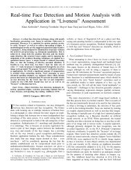
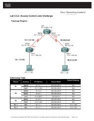
- Page 1: This document is exclusive property
- Page 5 and 6: Figure 2-1: Basic Pagent Configurat
- Page 7 and 8: Figure 2-3: Advanced Pagent Configu
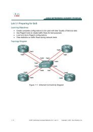
- Page 9 and 10: Figure 3-2: Ethernet Connectivity D
- Page 11 and 12: Lab 2.1 Configure CME using the CLI
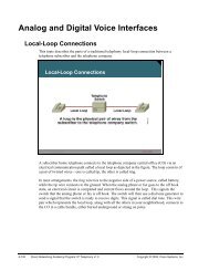
- Page 13 and 14: Figure 1-2: LAN Adapter Properties
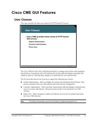
- Page 15 and 16: To enable the CME functionality of
- Page 17 and 18: Figure 4-1: IP Configuration on Hos
- Page 19 and 20: Figure 5-2: InstallShield System Ch
- Page 21 and 22: Figure 5-4: CIPC End-User License A
- Page 23 and 24: Click Install to begin installing C
- Page 25 and 26: Figure 5-8: CIPC Successful Install
- Page 27 and 28: Figure 6-2: CIPC Splash Screen If t
- Page 29 and 30: Figure 6-3: CIPC Network Preference
- Page 31 and 32: *Jan 30 06:47:37.155: skinny_add_so
- Page 33 and 34: Figure 7-1: Dialing from Host A to
- Page 35 and 36: Figure 7-3: In-Call Display on Host
- Page 37 and 38: R1(config-ephone)# codec g729r8 Clo
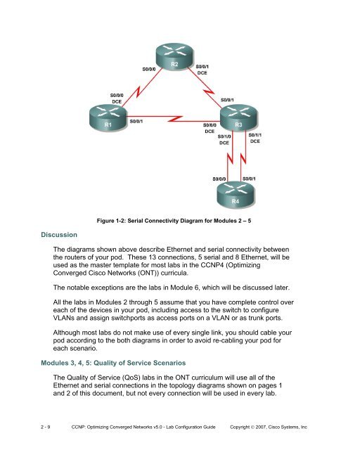
- Page 39 and 40: Lab 3.1 Preparing for QoS Learning
- Page 41 and 42: This lab guides you through creatin
- Page 43 and 44: This configuration will be used to
- Page 45 and 46: TrafGen(TGN:OFF,Fa0/0:8/8)# start T
- Page 47 and 48: Erase flash: before copying? [confi
- Page 49 and 50: Next, copy and paste the following
- Page 51 and 52: Destination filename [advanced-ios.
- Page 53 and 54:
Appendix A: Basic Pagent Configurat
- Page 55 and 56:
urst duration on 1000 to 3000 add f
- Page 57 and 58:
description Connection to R1 (FastE
- Page 59 and 60:
R4 NQR: fastethernet0/0 add tcp dat
- Page 61 and 62:
argument on the line, since everyth
- Page 63 and 64:
Figure 3-2: Network Connection Prop
- Page 65 and 66:
Step 4: Extract SDM on the Host Now
- Page 67 and 68:
Figure 4-3: Destination Selection D
- Page 69 and 70:
Figure 4-5: Final Extraction Wizard
- Page 71 and 72:
Figure 5-1: Welcome Screen for SDM
- Page 73 and 74:
Figure 5-3: Installation Location O
- Page 75 and 76:
Figure 5-5: Installation Prompt Fig
- Page 77 and 78:
Figure 6-1: SDM Launcher Window Cli
- Page 79 and 80:
Figure 6-5: SDM Load Progress Indic
- Page 81 and 82:
Figure 7-1: Installation Location O
- Page 83 and 84:
Figure 7-3: Router Connection Indic
- Page 86 and 87:
Figure 7-6: Confirmation Prompt Fig
- Page 88 and 89:
Step 8: Run SDM from the Router Fig
- Page 90 and 91:
Figure 8-3: SDM Authentication Dial
- Page 92 and 93:
Figure 9-1: SDM Dashboard 33 - 33 C
- Page 94 and 95:
accomplish this on R4 by loading th
- Page 96 and 97:
Choose Edit > Preferences. Make sur
- Page 98 and 99:
Figure 4-2: SDM QoS Wizard Select t
- Page 100 and 101:
Accept the default bandwidth percen
- Page 102 and 103:
Figure 4-7: QoS Policy, Summarized
- Page 104 and 105:
Figure 4-9: Command Delivery Notifi
- Page 106 and 107:
Figure 5-1: Interface Traffic Stati
- Page 108 and 109:
match protocol gnutella class-map m
- Page 110 and 111:
Lab 4.1 Default Queuing Tools Learn
- Page 112 and 113:
applied clock rate, but rather allo
- Page 114 and 115:
“The sum of all bandwidth allocat
- Page 116 and 117:
Encapsulation HDLC, loopback not se
- Page 118 and 119:
packets that will be dequeued from
- Page 120 and 121:
The show queue interface command di
- Page 122 and 123:
First, clear the interface counters
- Page 124 and 125:
model via the Resource Reservation
- Page 126 and 127:
Lab 4.2 Intermediate Queuing Tools
- Page 128 and 129:
R2(config-if)# no shutdown R2(confi
- Page 130 and 131:
Figure 3-1: Custom Queuing 5 - 16 C
- Page 132 and 133:
support for a deficit between round
- Page 134 and 135:
used by custom queuing. EIGRP hello
- Page 136 and 137:
although you can adjust the default
- Page 138 and 139:
Encapsulation HDLC, loopback not se
- Page 140 and 141:
hostname R2 ! interface Serial0/0/0
- Page 142 and 143:
Lab 4.3 TCP Header Compression Lear
- Page 144 and 145:
Interface Serial0/0/0 (compression
- Page 146 and 147:
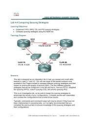
Lab 4.4 Comparing Queuing Strategie
- Page 148 and 149:
R2(config)# interface fastethernet
- Page 150 and 151:
than the bandwidth of the serial li
- Page 152 and 153:
What would happen if you put all th
- Page 154 and 155:
Preparation This lab uses the Basic
- Page 156 and 157:
Step 3: Configure NBAR Protocol Dis
- Page 158 and 159:
Mark as close as possible to the so
- Page 160 and 161:
not Negate this match result packet
- Page 162 and 163:
Class-map: critical (match-any) 138
- Page 164 and 165:
Would you use the match-all or matc
- Page 166 and 167:
5 minute rate 81000 bps Match: prot
- Page 168 and 169:
match protocol xwindows class-map m
- Page 170 and 171:
Lab 4.6 Class-based Marking, Shapin
- Page 172 and 173:
R4(config-if)# no shutdown R4(confi
- Page 174 and 175:
R1(config)# class-map match-any cri
- Page 176 and 177:
peak traffic rate of 400 kbps. You
- Page 178 and 179:
CIR 120000 (bps) Max. Buffers Limit
- Page 180 and 181:
service-policy innerpolicy Policy M
- Page 182 and 183:
! line vty 0 4 password cisco login
- Page 184 and 185:
R4# copy flash:advanced-ios.cfg sta
- Page 186 and 187:
R4(config-if)# ppp multilink R4(con
- Page 188 and 189:
Notice that the queuing strategy is
- Page 190 and 191:
R1(config-router)# network 172.16.0
- Page 192 and 193:
conformed 17433 packets, 5992721 by
- Page 194 and 195:
Lab 4.8 Shaping and Policing Learni
- Page 196 and 197:
R3(config)# interface serial 0/0/1
- Page 198 and 199:
1 TCP Fa0/0.10* 0.000033 0.367644 0
- Page 200 and 201:
hostname R3 ! policy-map mypolicy c
- Page 202 and 203:
Lab 4.9 QoS Pre-classify Learning O
- Page 204 and 205:
Step 1: Configure the Physical Inte
- Page 206 and 207:
Success rate is 100 percent (5/5),
- Page 208 and 209:
Reserved Conversations 0/0 (allocat
- Page 210 and 211:
Lab 5.1 AutoQoS Learning Objectives
- Page 212 and 213:
R2(config-if)# ip address 172.16.23
- Page 214 and 215:
AutoQoS by applying the auto discov
- Page 216 and 217:
What does the differentiated servic
- Page 218 and 219:
5 minute rate 53000 bps Queueing Ou
- Page 220 and 221:
Each router would need to use proce
- Page 222 and 223:
! policy-map AutoQoS-Policy-Se0/0/0
- Page 224 and 225:
Lab 6.1a Configuring a WLAN Control
- Page 226 and 227:
VTP Domain Name : CISCO VTP Pruning
- Page 228 and 229:
Step 6 passes over this VLAN to thi
- Page 230 and 231:
Figure 5-2: Modify the Properties f
- Page 232 and 233:
Step 7 Enable IP routing on DLS1. T
- Page 234 and 235:
Change the controller prompt to WLA
- Page 236 and 237:
! interface FastEthernet0/7 switchp
- Page 238 and 239:
Step 2 Explanation of VLANs: VLAN 1
- Page 240 and 241:
Step 5 Step 6 identifier that acces
- Page 242 and 243:
Figure 5-2: Modify the Properties f
- Page 244 and 245:
Step 7 R1 will route between all su
- Page 246 and 247:
Step 9 AP Manager Interface Netmask
- Page 248 and 249:
default-router 172.16.10.1 ! ip dhc
- Page 250 and 251:
Lab 6.2a Configuring a WLAN Control
- Page 252 and 253:
Step 3 Figure 2-2: WLAN Controller
- Page 254 and 255:
Figure 3-2: Creating a New VLAN Int
- Page 256 and 257:
Figure 3-4: Verify Existing VLAN In
- Page 258 and 259:
Figure 3-6: Verifying VLAN Interfac
- Page 260 and 261:
Figure 4-2: Edit the Configuration
- Page 262 and 263:
Figure 4-4: Adding a New SSID for W
- Page 264 and 265:
Figure 4-6: Verifying Final WLAN Co
- Page 266 and 267:
presented with the login screen for
- Page 268 and 269:
Figure 3-1: Interface Configuration
- Page 270 and 271:
Figure 3-3: Configuring VLAN Interf
- Page 272 and 273:
Figure 3-5: Configuring the VLAN 3
- Page 274 and 275:
Figure 4-1: Viewing Existing WLANs
- Page 276 and 277:
Figure 4-3: WLAN 1 without a Securi
- Page 278 and 279:
Figure 4-5: Configuring VLAN Associ
- Page 280 and 281:
Lab 6.3 Configuring a Wireless Clie
- Page 282 and 283:
Step 3 Click on Next. Then select I
- Page 284 and 285:
Step 5 If you are running Microsoft
- Page 286 and 287:
Click OK to Continue Step 6 The Set
- Page 288 and 289:
Current Status Screen Step 10 Wheth
- Page 290 and 291:
SSID configuration Step 12 Select t
- Page 292 and 293:
Advanced Configuration Options Step
- Page 294 and 295:
Step 16 Click on the Current Status
- Page 296 and 297:
Running Troubleshooting Tests 17 -
- Page 298 and 299:
Connectivity Diagram using a Wirele
- Page 300 and 301:
Figure 1-1: HTTP Access to the WLAN
- Page 302 and 303:
Figure 2-1: Interface Configuration
- Page 304 and 305:
Figure 2-3: Configuring VLAN Interf
- Page 306 and 307:
Figure 2-6: Viewing Existing WLANs
- Page 308 and 309:
Figure 2-8: Editing the VLAN Interf
- Page 310 and 311:
Figure 2-10: WLAN 1 with a WPA2 Sec
- Page 312 and 313:
Figure 3-2: Configuring Profile Opt
- Page 314 and 315:
Figure 3-5: Selecting a Wireless Pr
- Page 316 and 317:
Scenario Figure 1-2: Ethernet Conne
- Page 318 and 319:
Figure 1-1: CiscoSecure ACS Splash
- Page 320 and 321:
Use the default installation folder
- Page 322 and 323:
Figure 1-7: CiscoSecure ACS Install
- Page 324 and 325:
You must create a password for ACS
- Page 326 and 327:
If the Cisco Secure ACS administrat
- Page 328 and 329:
Figure 2-3: ACS AAA Client Configur
- Page 330 and 331:
Figure 2-5: ACS User Configuration
- Page 332 and 333:
Figure 2-7: ACS User-level Password
- Page 334 and 335:
Figure 2-9: System Security Protoco
- Page 336 and 337:
Figure 3-2: Authentication Dialog B
- Page 338 and 339:
Figure 4-2: New RADIUS Server Confi
- Page 340 and 341:
Figure 5-1: Interface Configuration
- Page 342 and 343:
Figure 5-3: Configuring VLAN Interf
- Page 344 and 345:
Figure 5-5: Verify Existing VLAN In
- Page 346 and 347:
Figure 5-7: Editing the Configurati
- Page 348 and 349:
Figure 6-1: Cisco ADU Profile Manag
- Page 350 and 351:
Figure 6-3: Wireless Security Optio
- Page 352 and 353:
Figure 6-5: Selecting a Wireless Pr
- Page 354 and 355:
Case Study: QoS and MLPPP Instructi
- Page 356 and 357:
Case Study: QoS and MLPPP Answer Ke
- Page 358:
R4#show run hostname R4 ! interface