Comparison of EndâUser Electric Power Meters for Accuracy
Comparison of EndâUser Electric Power Meters for Accuracy
Comparison of EndâUser Electric Power Meters for Accuracy

Create successful ePaper yourself
Turn your PDF publications into a flip-book with our unique Google optimized e-Paper software.
quite typical <strong>of</strong> brand discount stores. It is probable that other identical products<br />
with different or identical model names exist in the market. Photographs <strong>of</strong> the<br />
devices are presented in the Summaries section and may help to identify clones.<br />
3. Method<br />
3.1. Test environment<br />
Tests were carried out in the power quality laboratory in Department <strong>of</strong> <strong>Electric</strong>al<br />
Engineering <strong>of</strong> the Helsinki University <strong>of</strong> Technology TKK (Espoo, Finland). The<br />
laboratory’s electricity is routed through a filter <strong>for</strong> high frequency noise and the<br />
laboratory is also shielded from electric fields.<br />
During the tests, power was supplied by Schaffner Pr<strong>of</strong>line 2100 EMC test system.<br />
This generator can produce up to 5 kVA per phase and voltage between 0‐300 V<br />
with frequencies <strong>of</strong> 16‐500 Hz. During tests voltage was set to 230 V (50 Hz),<br />
corresponding to the nominal network voltage. This power supply ensured that<br />
different test sets utilized constant input voltage, independent <strong>of</strong> network voltage<br />
and free from other power instability issues.<br />
To evaluate the per<strong>for</strong>mance <strong>of</strong> the meters, a reference device was utilized.<br />
Reference measurements were taken with TOPAS 1000 power quality analyzer.<br />
TOPAS 1000 is an 8 channel computer‐operated power quality measurement<br />
device. It has a 16 bit precision and its channels are electrically isolated. TOPAS is<br />
meant <strong>for</strong> measuring three‐phase systems and since all channels are separate from<br />
each other, there is no galvanic connection between measurement connections.<br />
This means that all measurements are independent and can sample different<br />
voltages and currents.<br />
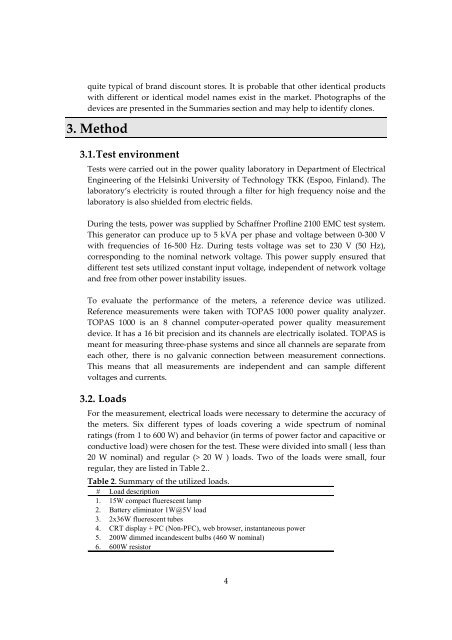
3.2. Loads<br />
For the measurement, electrical loads were necessary to determine the accuracy <strong>of</strong><br />
the meters. Six different types <strong>of</strong> loads covering a wide spectrum <strong>of</strong> nominal<br />
ratings (from 1 to 600 W) and behavior (in terms <strong>of</strong> power factor and capacitive or<br />
conductive load) were chosen <strong>for</strong> the test. These were divided into small ( less than<br />
20 W nominal) and regular (> 20 W ) loads. Two <strong>of</strong> the loads were small, four<br />
regular, they are listed in Table 2..<br />
Table 2. Summary <strong>of</strong> the utilized loads.<br />
# Load description<br />
1. 15W compact fluerescent lamp<br />
2. Battery eliminator 1W@5V load<br />
3. 2x36W fluerescent tubes<br />
4. CRT display + PC (Non-PFC), web browser, instantaneous power<br />
5. 200W dimmed incandescent bulbs (460 W nominal)<br />
6. 600W resistor<br />
4