Transfer Standards For Calibration of Air Monitoring Analyzers for ...
Transfer Standards For Calibration of Air Monitoring Analyzers for ...
Transfer Standards For Calibration of Air Monitoring Analyzers for ...
You also want an ePaper? Increase the reach of your titles
YUMPU automatically turns print PDFs into web optimized ePapers that Google loves.
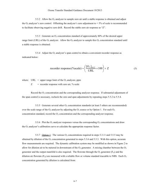
Ozone <strong>Transfer</strong> Standard Guidance Document 10/2013<br />
5.5.2 Allow the O 3 analyzer to sample zero air until a stable response is obtained and adjust<br />
the O 3 analyzer’s zero control. Offsetting the analyzer’s zero adjustment to + 5% <strong>of</strong> scale is recommended<br />
to facilitate observing negative zero drift. Record the stable zero air response as “Z”.<br />
5.5.3 Generate an O 3 concentration standard <strong>of</strong> approximately 80% <strong>of</strong> the desired upper<br />
range limit (URL) <strong>of</strong> the O 3 analyzer. Allow the O 3 analyzer to sample this O 3 concentration standard until<br />
a stable response is obtained.<br />
5.5.4 Adjust the O 3 analyzer’s span control to obtain a convenient recorder response as<br />
indicated below:<br />
[O3]<br />
OUT <br />
recorder response(%scale) 100<br />
Z<br />
(5)<br />
URL <br />
where: URL = upper range limit <strong>of</strong> the O 3 analyzer, ppm<br />
Z = recorder response with zero air, % scale<br />
Record the O 3 concentration and the corresponding analyzer response. If substantial adjustment <strong>of</strong><br />
the span control is necessary, recheck the zero and span adjustments by repeating steps 5.5.2 to 5.5.4.<br />
5.5.5 Generate several other O 3 concentration standards (at least 5 others are recommended)<br />
over the scale range <strong>of</strong> the O 3 analyzer by adjusting the O 3 source or by Option 1. <strong>For</strong> each O 3<br />
concentration standard, record the O 3 concentration and the corresponding analyzer response.<br />
5.5.6 Plot the O 3 analyzer responses versus the corresponding O 3 concentrations and draw<br />
the O 3 analyzer’s calibration curve or calculate the appropriate response factor.<br />
5.5.7 Option 1: The various O 3 concentrations required in steps 5.3.11 and 5.5.5 may be<br />
obtained by dilution <strong>of</strong> the O 3 concentration generated in steps 5.3.6 and 5.5.3. With this option, accurate<br />
flow measurements are required. The dynamic calibration system may be modified as shown in Figure 2 to<br />
allow <strong>for</strong> dilution air to be metered in downstream <strong>of</strong> the O 3 generator. A mixing chamber between the O 3<br />
generator and the output manifold is also required. The flowrate through the O 3 generator (F O ) and the<br />
dilution air flowrate (F D ) are measured with a reliable flow or volume standard traceable to NBS. Each O 3<br />
concentration generated by dilution is calculated from:<br />
A-7


