
You also want an ePaper? Increase the reach of your titles
YUMPU automatically turns print PDFs into web optimized ePapers that Google loves.
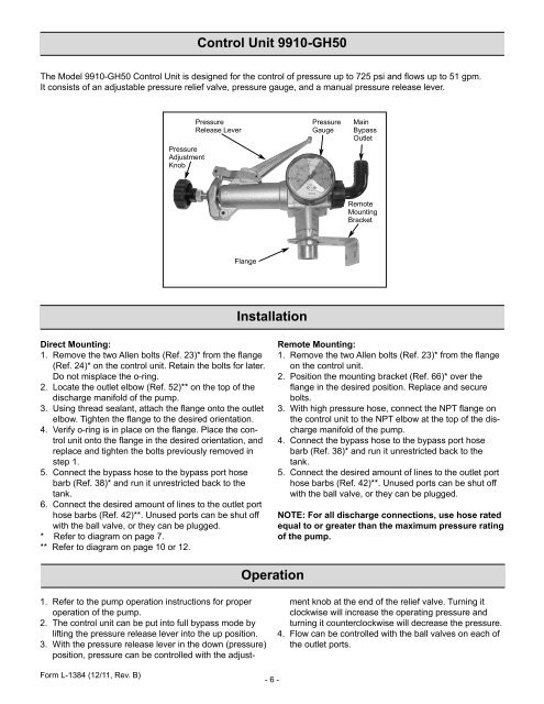
Control Unit 9910-GH50<br />
The Model 9910-GH50 Control Unit is designed for the control of pressure up to 725 psi and flows up to 51 gpm.<br />
It consists of an adjustable pressure relief valve, pressure gauge, and a manual pressure release lever.<br />
<strong>Pressure</strong><br />
Adjustment<br />
Knob<br />
<strong>Pressure</strong><br />
Release Lever<br />
<strong>Pressure</strong><br />
Gauge<br />
Main<br />
Bypass<br />
Outlet<br />
Remote<br />
Mounting<br />
Bracket<br />
Flange<br />
Installation<br />
Direct Mounting:<br />
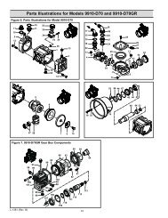
1. Remove the two Allen bolts (Ref. 23)* from the flange<br />
(Ref. 24)* on the control unit. Retain the bolts for later.<br />
Do not misplace the o-ring.<br />
2. Locate the outlet elbow (Ref. 52)** on the top of the<br />
discharge manifold of the pump.<br />
3. Using thread sealant, attach the flange onto the outlet<br />
elbow. Tighten the flange to the desired orientation.<br />
4. Verify o-ring is in place on the flange. Place the control<br />
unit onto the flange in the desired orientation, and<br />
replace and tighten the bolts previously removed in<br />
step 1.<br />
5. Connect the bypass hose to the bypass port hose<br />
barb (Ref. 38)* and run it unrestricted back to the<br />
tank.<br />
6. Connect the desired amount of lines to the outlet port<br />
hose barbs (Ref. 42)**. Unused ports can be shut off<br />
with the ball valve, or they can be plugged.<br />
* Refer to diagram on page 7.<br />
** Refer to diagram on page 10 or 12.<br />
Remote Mounting:<br />
1. Remove the two Allen bolts (Ref. 23)* from the flange<br />
on the control unit.<br />
2. Position the mounting bracket (Ref. 66)* over the<br />
flange in the desired position. Replace and secure<br />
bolts.<br />
3. With high pressure hose, connect the NPT flange on<br />
the control unit to the NPT elbow at the top of the discharge<br />
manifold of the pump.<br />
4. Connect the bypass hose to the bypass port hose<br />
barb (Ref. 38)* and run it unrestricted back to the<br />
tank.<br />
5. Connect the desired amount of lines to the outlet port<br />
hose barbs (Ref. 42)**. Unused ports can be shut off<br />
with the ball valve, or they can be plugged.<br />
NOTE: For all discharge connections, use hose rated<br />
equal to or greater than the maximum pressure rating<br />
of the pump.<br />
Operation<br />
1. Refer to the pump operation instructions for proper<br />
operation of the pump.<br />
2. The control unit can be put into full bypass mode by<br />
lifting the pressure release lever into the up position.<br />
3. With the pressure release lever in the down (pressure)<br />
position, pressure can be controlled with the adjustment<br />
knob at the end of the relief valve. Turning it<br />
clockwise will increase the operating pressure and<br />
turning it counterclockwise will decrease the pressure.<br />
4. Flow can be controlled with the ball valves on each of<br />
the outlet ports.<br />
Form L-<strong>1384</strong> (12/11, Rev. B)<br />
- 6-