Technical Paper Session Name: Energy ... - Boge Kompressoren
Technical Paper Session Name: Energy ... - Boge Kompressoren
Technical Paper Session Name: Energy ... - Boge Kompressoren

Create successful ePaper yourself
Turn your PDF publications into a flip-book with our unique Google optimized e-Paper software.
International Rotating Equipment Conference 2008, Düsseldorf<br />
A measurement like this is the ideal basis for evaluating a system design requirement. It can<br />
determine whether to choose a single compressor, several compressors at different sizes or<br />
maybe a frequency controlled compressor.<br />
Looking at our example plant from the beginning maybe a prior measurement would have<br />
shown that a combination of two differently sized compressors (probably 30 kW and 15 kW)<br />
would be more efficient. This combination would use the bigger compressor as the base load<br />
compressor and the smaller one for peak loads. This would help reduce the idling costs of<br />
almost 2,000 €/a by half.<br />
For compressor stations with several compressors it is very important to have an intelligent<br />
higher level control that decides what compressor combination should run at a certain required<br />
air flow, minimising the total idling time and costs. There are small base load switch over<br />
controls for small installations and powerful energy saving controls for stations with 16<br />
connected compressors or more. In stations with more than 2 compressors a higher level<br />
control should be used. Using this, instead of the formerly used cascaded settings for multiple<br />
compressor installations definitely saves energy and money. Only the most efficient compressor<br />
combination will run, thus minimising idling time whilst at the same time optimising the pressure.<br />
In all discussions about the efficiency of a compressed air station and plant layouts it is always<br />
important to see the compressed air production as a complete system. An efficient compressor<br />
does not automatically make an efficient compressed air system. One mistake in the plant<br />
layout can destroy the complete plant efficiency. It is therefore very important to include all<br />
components from the very beginning in order to create an optimised system.<br />
Heat recovery<br />
9% Heating of<br />
motor<br />
72%<br />
Oil cooler<br />
100%of<br />
generated heat<br />
4%<br />
Heat in<br />
compressed air<br />
13%<br />
Aftercooler<br />
2%<br />
Heat radiation<br />
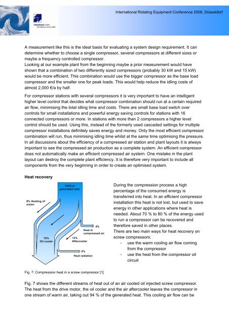
Fig. 7: Compression heat in a screw compressor [1]<br />
During the compression process a high<br />
percentage of the consumed energy is<br />
transferred into heat. In an efficient compressor<br />
installation this heat is not lost, but used to save<br />
energy in other applications where heat is<br />
needed. About 70 % to 80 % of the energy used<br />
to run a compressor can be recovered and<br />
therefore saved in other places.<br />
There are two main ways for heat recovery on<br />
screw compressors:<br />
- use the warm cooling air flow coming<br />
from the compressor<br />
- use the heat from the compressor oil<br />
circuit<br />
Fig. 7 shows the different streams of heat out of an air cooled oil injected screw compressor.<br />
The heat from the drive motor, the oil cooler and the air aftercooler leaves the compressor in<br />
one stream of warm air, taking out 94 % of the generated heat. This cooling air flow can be