Flow field development in a direct injection diesel engine with ...
Flow field development in a direct injection diesel engine with ...
Flow field development in a direct injection diesel engine with ...

You also want an ePaper? Increase the reach of your titles
YUMPU automatically turns print PDFs into web optimized ePapers that Google loves.
87<br />
Paul and Ganesan / International Journal of Eng<strong>in</strong>eer<strong>in</strong>g, Science and Technology, Vol. 2, No. 1, 2010, pp. 80-91<br />
5<br />
4<br />
Z=70<br />
1000rpm<br />
2000 rpm<br />
3000 rpm<br />
3<br />
W/Vp<br />
2<br />
1<br />
0<br />
0 10 20 30 40 50<br />
distance from cyl<strong>in</strong>der axis<br />
8. Swirl ratio <strong>in</strong>side the cyl<strong>in</strong>der<br />
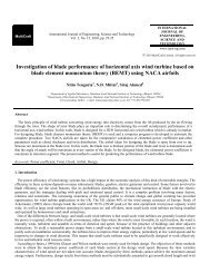
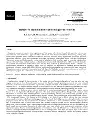
Figure 10 Radial distribution of mean swirl velocity component (W/Vp)<br />
<strong>in</strong> the piston at IVC for different speed <strong>with</strong> helical–spiral manifold<br />
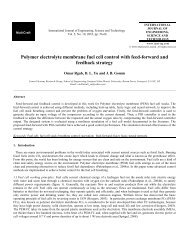
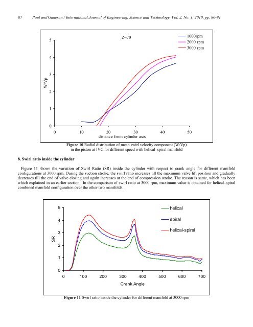
Figure 11 shows the variation of Swirl Ratio (SR) <strong>in</strong>side the cyl<strong>in</strong>der <strong>with</strong> respect to crank angle for different manifold<br />
configurations at 3000 rpm. Dur<strong>in</strong>g the suction stroke, the swirl ratio <strong>in</strong>creases till the maximum valve lift position and gradually<br />
decreases till the end of valve clos<strong>in</strong>g and aga<strong>in</strong> <strong>in</strong>creases at the end of compression stroke. The reason is same, which has been<br />
which expla<strong>in</strong>ed <strong>in</strong> an earlier section. In the comparison of swirl ratio at 3000 rpm, maximum value is obta<strong>in</strong>ed for helical–spiral<br />
comb<strong>in</strong>ed manifold configuration over the other two manifolds.<br />
5<br />
4<br />
3<br />
helical<br />
spiral<br />
helical-spiral<br />
SR<br />
2<br />
1<br />
0<br />
0 100 200 300 400 500 600 700<br />
Crank Angle<br />
Figure 11 Swirl ratio <strong>in</strong>side the cyl<strong>in</strong>der for different manifold at 3000 rpm