

Radio Doings May 22, 1927 - AmericanRadioHistory.Com
Radio Doings May 22, 1927 - AmericanRadioHistory.Com
Radio Doings May 22, 1927 - AmericanRadioHistory.Com

Create successful ePaper yourself
Turn your PDF publications into a flip-book with our unique Google optimized e-Paper software.
<strong>May</strong> ¿I <strong>Radio</strong> <strong>Doings</strong> 27<br />
enormous capacity of 2 to 10 mfd., but<br />
can expect almost anything In advanced<br />
regenerative a n d super. regenerative<br />
sets.. While I can appreciate that one<br />
stage of TRF plus regenerative detector<br />
is superior to TRF with straight detector,<br />
I have come to the conclusion<br />
that no matter how regeneration is<br />
obtained in TRF amplification, the results<br />
are the same. While I may be<br />
entirely wrong in this conclusion, I<br />
would like the favor of your opinion.<br />
ANSWER -The cascade regeneration<br />
principle described in the article to<br />
which you refer is more efficient than<br />
the other types you mention. for the<br />
reason that the regeneration control<br />
does not disturb the proper B and C<br />
voltage relationship, which is essential<br />
not as efficient a method of regeneration<br />
control as the actual tuning by inductance<br />
of the plato circuit. Tuning by<br />
inductance is always more efficient than<br />
tuning by capacity when the tuned circuit<br />
is followed by a vacuum tube for<br />
the reason that a higher voltage is built<br />
up to impress upon the grid of the tube.<br />
The capacity used as a coupling in the<br />
arrangement described should be 2 to 10<br />
mtnfd.<br />
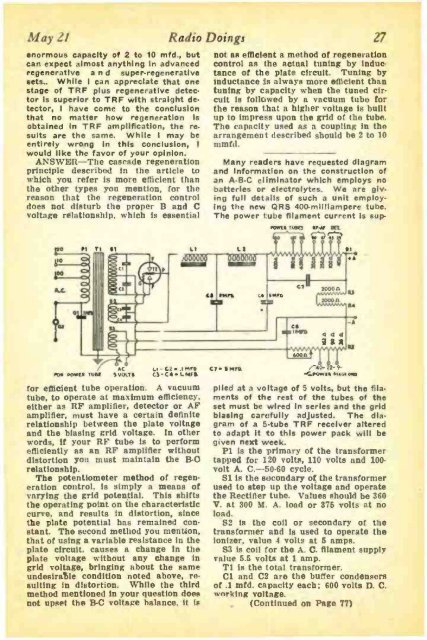
Many readers have requested diagram<br />
and Information on the construction of<br />
an A -B -C eliminator which employs no<br />
batteries or electrolytes. We are giving<br />
full details of such a unit employing<br />
the new QRS 400 -milliampere tube.<br />
The power tube filament current is suprpm<br />
ruso IOW OR<br />
C LI-C1.IMrG<br />
10S MKS tuM iVpl.r4 U-C4.1.AIM<br />
for efficient tube operation. A vacuum<br />
tube, to operate at maximum efficiency.<br />
either as RF amplifier, detector or AF<br />
amplifier, must have a certain definite<br />
relationship between the plate voltage<br />
and the biasing grid voltage. in other<br />
words, if your RF tube is to perform<br />
efficiently as an RF amplifier without<br />
distortion you must maintain the 11 -C<br />
relationship.<br />
The potentiometer method of regeneration<br />
control, is simply a means of<br />
varying the grid potential. This shifts<br />
the operating point on the characteristic<br />
curve, and results in distortion, since<br />
the plate potential has remained constant.<br />
The second method you mention,<br />
that of using a variable resistance in the<br />
plate circuit, causes a change in the<br />
plate voltage without any change in<br />
grid voltage, bringing about the same<br />
undesirable condition noted above, resulting<br />
in distortion. While the third<br />
method mentioned in your question does<br />
not upset the R -C voltage balance, it is<br />
C7. fNrC %4. - 2- 9-<br />
./....own eua o0<br />
plied at a voltage of 5 volts, but the filaments<br />
of the rest of the tubes of the<br />
set must be wired In series and the grid<br />
biasing carefully adjusted. The diagram<br />
of a 5 -tube TRF receiver altered<br />
to adapt it to this power pack will be<br />
given next week.<br />
Pl Is the primary of the transformer<br />
tapped for 120 volts, 110 volts and 100 -<br />
volt A. C. -50.60 cycle.<br />
S1 is the secondary of the transformer<br />
used to step up the voltage and operate<br />
the Rectifier tube. Values should be 360<br />
V. at 300 M. A. load or 375 volts at no<br />
load.<br />
S2 is the coil or secondary of the<br />
transformer and is used to operate the<br />
ionizer, value 4 volts at 5 amps.<br />
S3 is coil for the A. C. filament supply<br />
value 5.5 volts at I amp.<br />
TI is the total transformer.<br />
C1 and C2 aro the buffer condensers<br />
of .1 mfd. capacity each: 600 volts D. C.<br />
working voltage.<br />
(Continued on Page 77)


