The P-POD Payload Planner's Guide
The P-POD Payload Planner's Guide
The P-POD Payload Planner's Guide

You also want an ePaper? Increase the reach of your titles
YUMPU automatically turns print PDFs into web optimized ePapers that Google loves.
P-<strong>POD</strong> <strong>Payload</strong> Planner’s <strong>Guide</strong>: Revision B – 5/15/00 3 of 19<br />
2. PICOSATELLITE DEPLOYER DESCRIPTION<br />
This section of the document shall provide an overview of the CubeSat environment<br />
while onboard the deployer. <strong>The</strong> CubeSat provider shall be briefed on the following<br />
criteria required for integration into the deployer:<br />
2.1 Deployer System Overview<br />
2.2 CubeSat Containment and Deployer Interface<br />
2.3 CubeSat Launch Environment<br />
2.4 P-<strong>POD</strong> Orbital Environment<br />
Please refer to Section 3 for explicit CubeSat requirements.<br />
2.1 Deployer System Overview<br />
<strong>The</strong> P-<strong>POD</strong> System has two distinct release platforms, each with a unique deployer that<br />
has different requirements on the CubeSats themselves.<br />
2.1.1. Platform #1: P-<strong>POD</strong>1<br />
With this configuration, the deployment system requires less design refinement for the<br />
CubeSats. <strong>The</strong> published specification tolerances for the CubeSat, as well as the outer<br />
mounting surface area provide for easier manufacturing of the CubeSats. <strong>The</strong> ultimate<br />
aim of this system is to provide deployment services to clients with limited<br />
manufacturing capabilities, such as universities and high schools, since the P-<strong>POD</strong>1 can<br />
accept a wider variation in CubeSat design.<br />
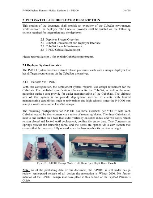
<strong>The</strong> mounting configuration for P-<strong>POD</strong>1 has three CubeSats per “<strong>POD</strong>,” with each<br />
CubeSat located by their corners via a series of mounting blocks. <strong>The</strong> three CubeSats sit<br />
next to one another on a base that slides vertically on roller slides, and two doors, which<br />
remain closed and locked until deployment, confine the entire base. Two Compression<br />
Springs provide the launching force, and the doors are opened via a cam system that<br />
ensures that the doors are fully opened when the base reaches its maximum height.<br />
Figure 2.1. P-<strong>POD</strong>1 Concept Model. (Left: Doors Open Right: Doors Closed)<br />
Note: As of the publishing date of this document, the P-<strong>POD</strong>1 is still under design<br />
review. Anticipated release of all design documentation is Winter 2000. No further<br />
mention of the P-<strong>POD</strong>1 design shall take place in this edition of the <strong>Payload</strong> Planner’s<br />
<strong>Guide</strong>.