controls
controls
controls

Create successful ePaper yourself
Turn your PDF publications into a flip-book with our unique Google optimized e-Paper software.
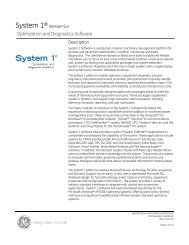
ConSig 8040 Series<br />
CONTROLS<br />
CONTROL & SIGNALING STATIONS<br />
8040 Features:<br />
• Attractive space efficient<br />
design.<br />
• A variety of enclosure sizes<br />
made of Fiberglass<br />
Reinforced Polyester (FRP).<br />
• Snap-on mounting of<br />
individual components.<br />
• High illumination LED pilot<br />
light from 12V to 254V, AC<br />
or DC with an operating life<br />
time over 100,000 hours.<br />
• A variety of pushbuttons.<br />
• Control switches.<br />
• Illuminated pushbutton.<br />
• Durable EPDM enclosure<br />
gaskets are concealed to<br />
protect from damage or<br />
premature aging by<br />
UV light and chemicals.<br />
• Fluorsilicate gasket in<br />
standard pushbutton<br />
actuators is suitable for a<br />
wide temperature range.<br />
INNOVATIVE EXPLOSION PROTECTION by R. STAHL 1-800-782-4357<br />
F
CONTENTS<br />
Control Stations . . . . . . . . . . . . . . . . . . . . . . . . . . . . . . . . . . . . . . . . . . . . . F-F33<br />
ConSig 8040 Series, FRP . . . . . . . . . . . . . . . . . . . . . . . . . . . . . . . . . . . . . . . . . . . . . . . . . . . . . . . . . . . . . . . . . . . . . . . . .F1-F15<br />
8146/5 Series Control Stations, FRP . . . . . . . . . . . . . . . . . . . . . . . . . . . . . . . . . . . . . . . . . . . . . . . . . . . . . . . . . . . . . . .F16-F22<br />
8125/5 Series Control Stations, Metallic . . . . . . . . . . . . . . . . . . . . . . . . . . . . . . . . . . . . . . . . . . . . . . . . . . . . . . . . . . . .F24-F30<br />
8560 Series, Small Fuses . . . . . . . . . . . . . . . . . . . . . . . . . . . . . . . . . . . . . . . . . . . . . . . . . . . . . . . . . . . . . . . . . . . . . . . . . . .F31<br />
8403/8404 Series, Ammeters & Voltmeters . . . . . . . . . . . . . . . . . . . . . . . . . . . . . . . . . . . . . . . . . . . . . . . . . . . . . . . . . . . . . .F32<br />
8082/1-1-01 Lockout Terminal . . . . . . . . . . . . . . . . . . . . . . . . . . . . . . . . . . . . . . . . . . . . . . . . . . . . . . . . . . . . . . . . . . . . . . .F33<br />
Our products are updated to the newest standard developments and technologies<br />
which makes it necessary to reserve the right to product changes without notice.<br />
INNOVATIVE EXPLOSION PROTECTION by R. STAHL 1-800-782-4357
CONTROLS<br />
ConSig 8040 Series<br />
CONTROL & SIGNALING STATIONS<br />
“PUTS YOU IN CONTROL”<br />
R. STAHL is setting new standards for function, design and technology<br />
with the new ConSig 8040 Series of control and signaling stations.<br />
Designed for complex industrial conditions and rough operation, the new<br />
ConSig 8040 system combines functionality with an attractive, modular<br />
design. The wide variety of UL Listed/CSA Certified control and signaling<br />
devices can be supplied, providing the ultimate in flexibility to meet the<br />
most demanding application requirements.<br />
Fiberglass Reinforced Polyester<br />
(FRP) enclosure<br />
Integral Mounting Slots<br />
Recessed EPDM<br />
Gasketing<br />
Explosion Protected<br />
LED Pilot Light<br />
Component Mounting Rail<br />
Pilot Light Bezel<br />
and Colored Lens<br />
Retainer Nut<br />
Station I.D. Label<br />
(optional)<br />
Ground Plate<br />
with Terminals<br />
and set screw<br />
Explosion Protected<br />
Contact Block<br />
Conduit Hub or<br />
Cable Gland Entry<br />
Actuator Gasket<br />
316 SST<br />
Cover Screws<br />
Dual Push-Button Actuator<br />
F1<br />
INNOVATIVE EXPLOSION PROTECTION by R. STAHL 1-800-782-4357
ConSig 8040 Series<br />
CONTROLS<br />
CONTROL & SIGNALING STATIONS<br />
The ConSig 8040 Series is a new generation of control and signaling stations utilizing<br />
explosion protected components with non-metallic control housings for the ultimate<br />
flexibility, safety and durability in Hazardous (Classified) and Hostile (Corrosive)<br />
Locations.<br />
This control and signaling station utilizes snap-on mounted components making<br />
field assembly quick and easy. Components include contact blocks with a variety of<br />
actuator options, LED pilot lights in all of the standard colors and voltages from 12V<br />
to 254V AC/DC, 2-pole and 4-pole control switches configurations and direct or indirect<br />
reading ammeters.<br />
Enclosures<br />
ConSig 8040 Series can be specified as one, two or three gang configurations and is<br />
made of Fiberglass Reinforced Polyester (FRP). Enclosure gasketing is durable EPDM<br />
which is concealed to protect it from premature aging by UV light and chemical elements.<br />
Components snap-on to the rail provided.<br />
Contact Blocks<br />
The contact system incorporates 8082 Series contact<br />
blocks which are individually explosion protected single<br />
pole units and are available as 1 N.O. or 1 N.C.<br />
The contact blocks incorporate a parallel bridge<br />
contact (H-contact) designed to ensure utmost<br />
contact reliability even with very low control<br />
voltages and currents. Any combination can be<br />
installed to provide a complete range of control<br />
configurations. Standard actuator styles include a double<br />
push-button, booted pushbutton and illuminated pushbutton.<br />
LED Pilot Lights<br />
ConSig 8040 Series introduces an extraordinary compact LED pilot light<br />
unit. The 8010 Series pilot light incorporates electronics which allow the same unit to<br />
operate at any voltage from 12 to 254 Volts, DC to 60 Hz. High output LEDs are used to<br />
provide superior illumination levels which are visible in direct sunlight from the front or<br />
side. The bezel is clear and the snap-on lenses are added in the colors Red, Green,<br />
Amber, White and Blue!<br />
CLASSIFICATIONS<br />
NEC- Class I, Zones 1 & 2 AEx de IIC T6<br />
Class I, Division 2, Groups A,B,C,D<br />
Class II, Division 2, Groups F,G<br />
Class III<br />
Enclosure Type 3,4 & 4X; IP66<br />
FILE No. E182378<br />
CEC- Class I, Zones 1 & 2 Ex de IIC T6<br />
Class I, Division 2, Groups A,B,C,D<br />
Class II, Divisions 1 & 2, Groups E,F,G<br />
Class III<br />
CSA ENCLOSURES 3, 4 & 4X; IP66<br />
CERTIFIED - FILE No. LR99480<br />
II 2 G Ex ed IIC T6, Zones 1 & 2, IP66<br />
II 2 D Ex tD A21 IP 65 T80˚C, T95˚C, T130˚C<br />
PTB 01 ATEX 1105<br />
Ambient Temperature Range:<br />
+40˚C (+104˚F) Max.<br />
–20˚C (–4˚F) Min.<br />
Special Ambient Temperature Range:*<br />
+60˚C (+140˚F) Max.<br />
–50˚C (–58˚F) Min.<br />
*Consult Factory<br />
Control Switches<br />
8008 Series control switches offer over 300 different switching configurations. They are<br />
available as 2-pole and 4-pole units incorporating maintained or spring return action.<br />
The control switch is for quick and easy snap-on mounting. Three styles of handles, with<br />
or without padlocking provision can be used in conjunction with the switches.<br />
Illuminated Push-Buttons<br />
Illuminated push-buttons make it possible to have control<br />
and signaling functions in the space of one. This is<br />
achieved by combining the 8082 Series Contact Blocks<br />
and 8010 Series LED Pilot Lights under a special<br />
illuminated pushbutton actuator which is spring return<br />
with a clear bezel and five colored snap-in filter disks<br />
in Red, Green, Amber, White and Blue.<br />
Ammeters<br />
ConSig 8040 Series offers a cost effective ammeter station<br />
as a solution for applications in a Hazardous (Classified) Location.<br />
The 8405 Series ammeter is a moving iron core instrument available<br />
in direct or indirect read versions. A manually adjustable red pointer<br />
provides quick and easy comparison of the actual circuit operation.<br />
The ammeter is for quick and easy snap-on mounting.<br />
INNOVATIVE EXPLOSION PROTECTION by R. STAHL 1-800-782-4357<br />
F2
CONTROLS<br />
ConSig 8040 Series<br />
PRE-CONFIGURED CONTROL STATIONS<br />
Ordering Information<br />
FUNCTION<br />
“START”<br />
Green Momentary<br />
Pushbutton, 1 NO<br />
“STOP”<br />
RED Momentary<br />
Pushbutton, 1NC<br />
“E-STOP”<br />
SMALL RED Maintained<br />
Mushroom, 1 NC<br />
“E-STOP”<br />
JUMBO RED Maintained<br />
Pushbutton, 1 NC<br />
“E-STOP”<br />
Keyed Maintained<br />
Red Mushroom, 1 NC<br />
“OFF - ON”<br />
Selector Switch<br />
2-Position/10 Amps<br />
“LOCAL REMOTE”<br />
Selector Switch<br />
2-Positions/10 Amps<br />
( )<br />
13<br />
23<br />
( )<br />
( )<br />
CONTACT 13 SYMBOL<br />
CATALOG<br />
START NUMBER<br />
IEC 13 NEMA<br />
1<br />
13<br />
START<br />
13<br />
13 14<br />
START<br />
1<br />
13<br />
START<br />
1<br />
13 START START<br />
14<br />
8040/114 1 - X011<br />
14<br />
START<br />
1<br />
14<br />
14 11<br />
1<br />
14<br />
STOP 2<br />
13 14<br />
11<br />
11<br />
11<br />
START<br />
11<br />
STOP STOP 21<br />
2<br />
12<br />
STOP 8040/114 2<br />
11<br />
- Y012<br />
14<br />
12 11<br />
STOP 2<br />
12 12 12<br />
STOP<br />
STOP 2<br />
13 11<br />
11 12<br />
3<br />
START STOP<br />
11<br />
11<br />
STOP 11<br />
12<br />
STOP<br />
3<br />
11<br />
8040/114 12<br />
- Y100 3<br />
14<br />
12<br />
12<br />
STOP<br />
12 12 11<br />
12<br />
3<br />
STOP<br />
12 11<br />
3<br />
11<br />
STOP<br />
11 11<br />
11<br />
11<br />
4<br />
8040/114 3<br />
STOP<br />
STOP 42<br />
- Y150 4<br />
12 STOP ( )<br />
X2 12<br />
11<br />
12<br />
STOP 4<br />
12<br />
45° 12<br />
135° 12<br />
( 13)<br />
12 14<br />
OFF ON<br />
23 24 11<br />
14<br />
24 13 23 OFF STOP ON<br />
STOP 4<br />
11<br />
° ° 12 11<br />
( ) 13 23<br />
STOP 8040/114 - Y090<br />
° °<br />
STOP 3 4<br />
° °<br />
4<br />
14 24<br />
( )<br />
( )<br />
X1<br />
45° 135°<br />
° °<br />
14 24<br />
12<br />
12<br />
12<br />
13 23<br />
90° 90° 135°<br />
13 135° X14<br />
X<br />
23 142424<br />
11<br />
90° 13 23<br />
135° 13 23<br />
° °<br />
45° ° 135° °<br />
11 14 2412<br />
23 1424<br />
24<br />
90° 135° 12 90°<br />
11 23<br />
11 12 °<br />
90° ° X<br />
23 24<br />
135° °<br />
12 24<br />
° X<br />
11 23 12 24<br />
° °<br />
90° 135° 11 23<br />
° °<br />
12 24<br />
HAND<br />
OFF<br />
STOP 8040/114 4 - 02MN1<br />
OFF<br />
ON<br />
AUTO<br />
LOCAL REMOTE<br />
new 2/9/2001<br />
8040/114 - U2MN4<br />
“Hand - O - Auto”<br />
Maintained Selector Switch<br />
3-Positions/10 Amps<br />
12 24<br />
13 23<br />
45° 45° X 135°<br />
1390°<br />
14<br />
23135°<br />
X24<br />
90° 14 24<br />
H H O X1O A<br />
X213<br />
° °<br />
23<br />
HAND<br />
OFF<br />
AUTO<br />
8040/114 - 03MMN3<br />
14<br />
°<br />
24<br />
°<br />
23 1114<br />
24<br />
13<br />
“START-STOP”<br />
Double PB Momentary<br />
1 NO / 1 NC<br />
24 12<br />
14<br />
23 11<br />
11<br />
START<br />
START<br />
STOP<br />
STOP<br />
8040/114 - U2312<br />
12<br />
24 12<br />
“PILOT LIGHT”<br />
RED LED<br />
12V-254V AC / DC<br />
X1<br />
X2<br />
8040/114 - PLR0<br />
“PILOT LIGHT”<br />
GREEN LED<br />
12V-254V AC / DC<br />
X1<br />
X2<br />
8040/114 - PLG0<br />
All above stations include one 3/4" hub bottom.<br />
F3<br />
INNOVATIVE EXPLOSION PROTECTION by R. STAHL 1-800-782-4357
ConSig 8040 Series<br />
CONTROLS<br />
PRE-CONFIGURED CONTROL STATIONS<br />
Ordering Information<br />
FUNCTION<br />
1 2 3<br />
IEC<br />
CONTACT SYMBOL<br />
NEMA<br />
CATALOG<br />
NUMBER<br />
RED LED<br />
Pilot Light<br />
12V-254V<br />
AC / DC<br />
---- ----<br />
X1<br />
X2<br />
8040/124 - PLR0<br />
“START”<br />
Green<br />
Momentary<br />
Pushbutton<br />
1 NO / 1 NC<br />
---- ----<br />
23 11<br />
24 12<br />
8040/124 - U011<br />
“E-STOP”<br />
RED JUMBO<br />
Mushroom<br />
Maintained<br />
2 NC<br />
---- ----<br />
12 12 22 22<br />
I - I0<br />
- 0<br />
11 11 21 21<br />
8040/124 - C150<br />
“OFF - ON”<br />
Maintained<br />
Control Switch<br />
2-Pos./2-Pole<br />
10 amps<br />
---- ----<br />
13<br />
23<br />
45° 135°<br />
14<br />
24<br />
13 23<br />
° °<br />
°<br />
14 24<br />
°<br />
OFF<br />
ON<br />
8040/124 - N021<br />
RED LED<br />
Pilot Light<br />
12V-254V<br />
AC / DC<br />
“H - O - A”<br />
Maintained<br />
Control Switch<br />
3-Pos./2-Pole<br />
10 amps<br />
“LOCAL<br />
REMOTE”<br />
Control Switch<br />
2-Positions<br />
10 amps<br />
“STOP-RUN<br />
START”<br />
Control Switch<br />
3-Pos./2-Pole<br />
Spring Return<br />
From Right<br />
10 amps<br />
“START”<br />
Momentary<br />
Green<br />
Pushbutton<br />
1 NO / 1 NC<br />
“OFF-ON”<br />
Maintained<br />
Control Switch<br />
2-Pos./2-Pole<br />
10 amps<br />
---- ----<br />
“STOP”<br />
Momentary<br />
Red Pushbutton<br />
1 NO / 1 NC<br />
----<br />
---- ----<br />
----<br />
X1<br />
X1<br />
X1<br />
90°<br />
X2<br />
45° 135° 135°<br />
13 13 45° 14 14135°<br />
23 23 13 24 24 14<br />
23 24<br />
45° 135° 13 23<br />
13 13 1423<br />
° 13 ° 23<br />
23 ° 24<br />
°<br />
°<br />
14 24<br />
°<br />
°<br />
° °<br />
14 24<br />
° 14 24<br />
13 23<br />
° °<br />
°<br />
14 24<br />
°<br />
23 11<br />
23 11<br />
X2<br />
45° 135°<br />
11 12<br />
23 24<br />
90°<br />
11 23 90° 135°<br />
° 11 ° 90° 12135°<br />
23 11 24 12<br />
° 23<br />
12<br />
°<br />
24<br />
24<br />
11 23<br />
° 11 ° 23<br />
45° 135° °<br />
11 12 ° °<br />
12 24<br />
° °<br />
23 24<br />
90° 90° 135°<br />
12 24<br />
11 11 23 12<br />
23 ° ° 24<br />
°<br />
12 1124<br />
° 23<br />
° °<br />
45°<br />
° °<br />
12<br />
135°<br />
24<br />
13 14<br />
23 24<br />
90°<br />
H O 13<br />
A °<br />
23<br />
°<br />
14<br />
°<br />
24<br />
°<br />
24 12<br />
24 12<br />
23 2311<br />
11<br />
24 12<br />
24 12<br />
X1<br />
X2<br />
X2<br />
OFF<br />
OFF<br />
OFF<br />
HAND<br />
HAND<br />
OFF<br />
ON<br />
ON<br />
ON<br />
OFF<br />
LOCAL REMOTE<br />
LOCAL REMOTE<br />
HAND<br />
OFF<br />
START START STOP STOP<br />
AUTO<br />
AUTO<br />
new 2/9/2001<br />
new 2/9/2001<br />
8040/224 - PLR0-N021<br />
8040/124 - N273<br />
---- ---- 8040/124 - N164<br />
STOP<br />
OFF<br />
RUN<br />
ON<br />
AUTO<br />
LOCAL REMOTE<br />
START<br />
new 2/9/2001<br />
8040/124 - N385<br />
8040/224 - U011-U012<br />
RED LED Pilot<br />
Light<br />
12V- 254V<br />
AC / DC<br />
“START-STOP”<br />
Double PB<br />
Momentary<br />
1 NO / 1 NC<br />
----<br />
X1 X2<br />
23 11<br />
23<br />
24 24 12<br />
11<br />
23 11<br />
•<br />
START START STOP<br />
STOP<br />
8040/224 - PLR0-U2312<br />
RED LED<br />
Pilot Light<br />
12V-254V<br />
AC / DC<br />
“Start”<br />
Green<br />
Momentary<br />
Pushbutton<br />
1 NO / 1 NC<br />
“STOP”<br />
Red<br />
Momentary<br />
Pushbutton<br />
1 NO / 1 NC<br />
12<br />
X1 X2<br />
24 12<br />
X1 X1 X2 X2<br />
23 11<br />
23 11<br />
23 11<br />
24 12<br />
24 12<br />
23 23 11 11<br />
24 12<br />
23 11<br />
24 12<br />
START<br />
•<br />
•<br />
START • STOP<br />
START STOP<br />
STOP<br />
8040/3 34 - PLR0-U011-U012<br />
24 12<br />
All above stations include one 3/4" hub bottom.<br />
24 12<br />
INNOVATIVE EXPLOSION PROTECTION by R. STAHL 1-800-782-4357<br />
F4
CONTROLS<br />
ConSig 8040 Series<br />
Start Here<br />
ConSig<br />
Control Station<br />
8040 /<br />
CUSTOM CONFIGURATION LOGIC<br />
Enclosure Size<br />
( __ __ )<br />
Enclosure<br />
Entry or Entries<br />
( __ )<br />
CLASSIFICATIONS<br />
NEC- Class I, Zones 1 & 2 AEx de IIC T6<br />
Class I, Division 2, Groups A,B,C,D<br />
Class II, Division 2, Groups F,G<br />
Class III<br />
Enclosure Type 3, 4 & 4X; IP66<br />
FILE No. E182378<br />
CEC- Class I, Zones 1 & 2 Ex de IIC T6<br />
Class I, Division 2, Groups A,B,C,D<br />
Class II, Divisions 1 & 2, Groups E,F,G<br />
Class III<br />
CSA ENCLOSURES 3, 4 & 4X; IP66<br />
CERTIFIED - FILE No. LR99480<br />
See page F2<br />
HOUSING MATERIAL AND GASKETING<br />
Fiberglass Reinforced Polyester (FRP)<br />
with EPDM recessed gasketing.<br />
FEATURES<br />
The ConSig 8040 Series of control &<br />
signaling stations with its many enclosure<br />
sizes and components is uniquely flexible. If<br />
the preconfigured control stations on pages<br />
F3 and F4 do not meet your specific application<br />
needs, take advantage of the flexibility of<br />
ConSig 8040 and use the custom configuration<br />
logic tables on the right to custom configure a<br />
control station which can exactly meet your<br />
particular application.<br />
How to use configuration logic tables:<br />
Fill in the blanks in the light blue striped<br />
fields located on the top of pages F5 and F6<br />
left to right from information stated below<br />
the individual fields.<br />
Step 1: Select enclosure size<br />
Step 2: Select entry or entries<br />
Step 3: Select the device mounted to<br />
the cover as well as the device<br />
mounted into the back box.<br />
Step 4: Repeat step 3 when configuring<br />
a two-gang station.<br />
Step 5: Repeat step 3 when configuring<br />
a three-gang station.<br />
DIMENSIONS<br />
For dimensional data see page F15.<br />
Expanded<br />
Expanded<br />
11<br />
1-device<br />
Compact<br />
12<br />
1-device<br />
22<br />
2-device<br />
64<br />
2-device<br />
33<br />
3-device<br />
42<br />
Ammeter<br />
54<br />
Ammeter<br />
plus<br />
1-device<br />
73<br />
Deep<br />
84<br />
Deep<br />
One<br />
4 Pole<br />
switch<br />
Two<br />
4 Pole<br />
switch<br />
94<br />
Ammeter<br />
1- 4 Pole<br />
switch<br />
Deep<br />
Entry Type:<br />
Conduit Hub-<br />
0 = 1/2" Hub Top Feed<br />
1 = 1/2" Hub Bottom Feed<br />
2 = 1/2" Hub Feed-Thru<br />
3 = 3/4" Hub Top Feed<br />
4 = 3/4" Hub Bottom Feed<br />
5 = 3/4" Hub Feed-Thru<br />
Compression Gland - FOR IEC CENELEC<br />
6 = M25 Gland Top Feed<br />
7 = M25 Gland Bottom Feed<br />
8 = M25 Gland Feed-Thru<br />
9 = Special<br />
Threaded Opening-In Internal Ground Plate<br />
A = 1/2" NPT plate Top Feed<br />
B = 1/2" NPT plate Bottom Feed<br />
C = 1/2" NPT plate Feed-Through<br />
D = 3/4" NPT plate Top Feed<br />
E = 3/4" NPT plate Bottom Feed<br />
F = 3/4" NPT plate Feed-Through<br />
G = 1/2" NPT plug Feed-Through<br />
H = 3/4" NPT plug Feed-Through<br />
L = M20 Plate Bottom Feed<br />
M = M25 Plate Bottom Feed<br />
Other Special Entries<br />
Non-Metallic Cable Glands<br />
J = M20 Gland Bottom Feed<br />
K = M20 Gland Feed-Through<br />
Metal Clad Cable Connectors<br />
Q = MCR050 Bottom Feed<br />
V = MCR075 Bottom Feed<br />
8040 Control Station Coupling<br />
Z = Coupling Frame Bottom<br />
F5<br />
INNOVATIVE EXPLOSION PROTECTION by R. STAHL 1-800-782-4357
First or only position<br />
(____________ )<br />
ConSig 8040 Series<br />
CUSTOM CONFIGURATION LOGIC<br />
Device Specification (1, 2 or 3 devices described from top to bottom)<br />
_<br />
Second position<br />
(____________ )<br />
_<br />
Third position<br />
( _____________ )<br />
CONTROLS<br />
Example<br />
8040/334 - PLR0 - U2312 - Y090<br />
Contact type<br />
X = 1 N.O.<br />
Y = 1 N.C.<br />
U = 1 N.O./ 1 N.C.<br />
O = 2 N.O.<br />
C = 2 N.C.<br />
M = 2 N.C./ 1 N.O.<br />
W = 1 N.C./ 2 N.O.<br />
T = 3 N.C.<br />
R = 3 N.O.<br />
D = 2 N.O./ 2 N.C.<br />
only with actuator 23 in<br />
enclosures 12, 54 & 64<br />
X = 1 N.O.<br />
Y = 1 N.C.<br />
U = 1 N.O./ 1 N.C.<br />
O = 2 N.O.<br />
C = 2 N.C.<br />
PL<br />
Actuator type<br />
N = Non-lockable<br />
S = Small-lockable<br />
L = Large lockable<br />
Spring Return<br />
SR =<br />
SG =<br />
SA =<br />
SW =<br />
SB =<br />
PUSHBUTTONS<br />
Actuator type<br />
01 = Standard Momentary<br />
02 = Booted Momentary<br />
03 = Black Momentary small Mushroom<br />
09 = Keyed E-STOP Red Mushroom Maintained<br />
10 = E-STOP Red small Mushroom Maintained<br />
12 = Black small Mushroom Maintained<br />
13 = Red small Mushroom Maintained<br />
15 = Emergency STOP Red Jumbo Mushroom Maint.<br />
23 = Double Pushbutton Momentary<br />
P733 = Device Close-up Plug<br />
SELECTOR SWITCHES<br />
2SK<br />
2MK<br />
3SSK<br />
3MMK<br />
3SMK<br />
3MSK<br />
Color<br />
A = amber<br />
B = blue<br />
G = green<br />
R = red<br />
W = white<br />
2SN<br />
2MN<br />
3SSN<br />
3MMN<br />
3SMN<br />
3MSN<br />
PILOT LIGHTS<br />
2SL<br />
2ML<br />
3SSL<br />
3MML<br />
3SML<br />
3MSL<br />
CONTROL SWITCHES<br />
Switch arrangements 2 pole<br />
02 = 2-pos. Maintained (OFF-ON)<br />
05 = 2-pos. Maintained (ON-OFF)<br />
16 = 2-pos. Maintained (LOCAL-REMOTE)<br />
27 = 3-pos. Maintained (HAND-O-AUTO)<br />
38 = 3-pos. Maint., Spring Return from<br />
Right (OFF-RUN-START)<br />
Switch arrangements 4 pole<br />
102 = 2-pos. OFF-ON<br />
only for deep<br />
106 = 2-pos. LOCAL-REMOTE enclosures<br />
}<br />
119 = 3-pos. HOA<br />
73, 84 & 94<br />
For more switching arrangements see pgs. F11 and F12.<br />
ILLUMINATED PUSHBUTTONS<br />
Colors<br />
red<br />
green<br />
amber<br />
white<br />
blue<br />
Contact type<br />
X = 1 N.O.<br />
Y = 1 N.C.<br />
U = 1 N.O. / 1 N.C.<br />
O = 2 N.O.<br />
C = 2 N.C.<br />
}<br />
Legend<br />
0 = none<br />
1 = START<br />
2 = STOP<br />
3 = ON<br />
4 = OFF<br />
5 = RUN<br />
6 = RESET<br />
7 = OPEN<br />
8 = CLOSE<br />
9 = special<br />
(specify from F14)<br />
Note:<br />
For Actuator<br />
Descriptions<br />
see page F8<br />
Legend<br />
Same # as<br />
pushbutton<br />
Legend<br />
0 = none<br />
1 = OFF-ON<br />
2 = ON-OFF<br />
3 = HAND-O-AUTO<br />
4 = LOCAL-REMOTE<br />
5 = STOP-RUN-START<br />
6 = O - I<br />
7 = blank one line text<br />
8 = blank two lines text<br />
9 = special (specify)<br />
Legend<br />
Same # as<br />
pushbuttons<br />
PUSHBUTTON LOCKOUTS/GUARDS<br />
LK01 = Momentary Lockout (01 & 02)<br />
LK02 = Momentary Exclusion (01 & 02)<br />
LK03 = Small Mushroom Guard (03,10,12 &13)<br />
LK10 = Small Mushroom Lockout (03,10,12 &13)<br />
LK11 = Small Mushroom Pin & Chain Lockout<br />
(03,10,12, 13 & 15)<br />
LK20 = Small Mushroom Exclusion Lockout<br />
(03,10,12 & 13)<br />
LK21 = Momentary Pushbutton (01 & 02) exclusion<br />
LK23 = Double Pushbutton Lockout, 1-device (23)<br />
Dial Increments<br />
P1 = 0-10 scale<br />
P2 = 0-100 scale<br />
P6 = 0-6 scale<br />
Direct reading<br />
(2X overload):<br />
AD....<br />
A1....<br />
For 1 AMP C.T.<br />
or<br />
A5....<br />
For 5 AMP C.T.<br />
POTENTIOMETERS<br />
Resistance (Ohm) Range<br />
01 = 100Ω 06 = 4.7 kΩ 11 = 220 kΩ<br />
02 = 220Ω 07 = 10 kΩ 12 = 470 kΩ<br />
03 = 470Ω 08 = 22 kΩ 13 = 1 MΩ<br />
04 = 1kΩ 09 =47kΩ 14 = 2.2 MΩ<br />
05 = 2.2 kΩ 10 = 100 kΩ 15 = 4.7 MΩ<br />
AMMETERS<br />
Scales<br />
0-0.02/0.04A<br />
0-1/2A<br />
0-4/8A<br />
0-10/20A<br />
0-15/30A<br />
Indirect reading for Current Transformer (5X overload):<br />
0-1/5 0-50/250<br />
0-2/10 0-75/375<br />
0-5/25 0-100/500<br />
0-10/50 0-150/750<br />
0-15/75 0-200/1000<br />
0-20/100 0-250/1250<br />
0-30/150 0-300/1500<br />
0-40/200<br />
Ammeter Example:<br />
8040/424-A1 20/100, Ammeter for CT 1AMP,<br />
Scale 0-20/100A in<br />
Enclosure Size 42 with 3/4" NPT Bottom Hub.<br />
INNOVATIVE EXPLOSION PROTECTION by R. STAHL 1-800-782-4357<br />
F6
CONTROLS<br />
Control Components<br />
PUSH BUTTON ACTUATORS<br />
Ordering Information<br />
APPROVALS<br />
FILE No. E182378<br />
CERTIFIED - FILE No. LR99480<br />
PTB 01 ATEX 1129 U<br />
ACTUATOR DESCRIPTION<br />
Standard Momentary<br />
Pushbutton<br />
1.5" (38mm) O.D.<br />
Legend disks to be ordered<br />
separately, see page F14.<br />
INDIVIDUAL<br />
ORDER<br />
CATALOG NUMBER<br />
8602A0001-1-S<br />
CONTACT<br />
BLOCK<br />
ASSEMBLY CODE<br />
ACTUATOR<br />
CODE<br />
01 __<br />
LEGEND<br />
DISK<br />
0 = none<br />
STAHL offers a large variety of push-button<br />
actuator versions including momentary<br />
and maintained action in standard, booted,<br />
mushroom, keyed and selector switch<br />
styles. A new double push-button actuator<br />
combines two control functions in the<br />
space of one with the same size button.<br />
Up to three 8082 contact blocks can<br />
be mounted under each push-button<br />
actuator. Under the double momentary<br />
push-button 23, up to four 8082 contact<br />
blocks can be mounted. Legend disks, in<br />
a variety of standard markings, snap into<br />
the center of the actuator making the<br />
button function easily identifiable.<br />
Booted Momentary<br />
Pushbutton<br />
1.5" (38mm) O.D.<br />
Legend disks to be ordered<br />
separately, see page F14.<br />
Double Momentary<br />
Pushbutton<br />
1.5" (38mm) O.D.<br />
Legend disks to be ordered<br />
separately, see page F14.<br />
Black Mushroom<br />
Pushbutton<br />
1.5" (38mm) O.D.<br />
Momentary action. Legend<br />
disks to be ordered separately,<br />
see page F14.<br />
8602A0002-1-S<br />
8602A0023-1-S<br />
8602A0003-1-S<br />
M = 2 x NC<br />
1 x NO<br />
W = 1 x NC<br />
2 x NO<br />
T = 3 x NC<br />
02 __<br />
23 __<br />
03 __<br />
1 = START<br />
2 = STOP<br />
3 = ON<br />
Emergency Stop Red<br />
Pushbutton<br />
1.5 " (38mm) O.D.<br />
Maintained action. Turn-to-<br />
Release. Arrow disk and<br />
yellow washer supplied.<br />
Maintained Black<br />
Mushroom Pushbutton<br />
1.5 " (38mm) O.D.<br />
Maintained action. Turn-to-<br />
Release. Red arrow disk<br />
included<br />
8602A0010-1-S<br />
8602A0012-1-S<br />
R = 3 x NO<br />
X = 1 x NO<br />
Y = 1 x NC<br />
10 __<br />
12 __<br />
4 = OFF<br />
5 = RUN<br />
6 = RESET<br />
Maintained Red<br />
Mushroom Pushbutton<br />
1.5 " (38mm) O.D.<br />
Maintained action.<br />
Turn-to-Release. Legend<br />
disks to be ordered separately,<br />
see page F14.<br />
8602A0013-1-S<br />
U = 1 NO + 1<br />
NC<br />
13 __<br />
7 = OPEN<br />
Emergency Stop (Jumbo)<br />
Red Pushbutton<br />
2.16" (55mm) O.D.<br />
Maintained action.<br />
Turn-to-Release. Arrow disk<br />
and yellow washer supplied.<br />
8602A0015-1-S<br />
O = 2 x NO<br />
C = 2 x NC<br />
15 __<br />
8 = CLOSE<br />
Emergency Stop Red<br />
Mushroom<br />
1.5 " (38mm) O.D.<br />
Maintained action. Key-to-<br />
Release from maintained<br />
position. Arrow disk and<br />
yellow washer supplied.<br />
8602A0009-1-S<br />
-MS1<br />
D = 2 x NC<br />
➀ 2 x NO<br />
09 __<br />
9 = special<br />
(state text<br />
w/order)<br />
➀ Only possible under double pushbutton 23 in enclosures 12, 54 & 64.<br />
F7<br />
INNOVATIVE EXPLOSION PROTECTION by R. STAHL 1-800-782-4357
Control Components<br />
CONTROLS<br />
SELECTOR SWITCH ACTUATORS<br />
Ordering Information<br />
ACTUATOR DESCRIPTION<br />
Key Operated Switch -<br />
2 Positions<br />
Maintained action. Key<br />
removable in both positions.<br />
Key Operated Switch -<br />
3 Positions<br />
Maintained action. Key<br />
removable in all positions.<br />
INDIVIDUAL<br />
ORDER<br />
CATALOG NUMBER<br />
8602A0008-<br />
1-2-r-V-MS1<br />
8602A0008-<br />
1-3-rr-V-MS1<br />
ASSEMBLY CODE<br />
CONTACT ACTUATOR<br />
BLOCK(S) CODE<br />
X = 1 x NO<br />
__2SK__<br />
__2MK__<br />
__3SSK__<br />
*<br />
*<br />
__3MMK__<br />
__3SMK__<br />
__3MSK__<br />
LEGEND<br />
0 = none<br />
1 = OFF-<br />
ON<br />
2 = ON-<br />
OFF<br />
3 = HAND-<br />
OFF-<br />
AUTO<br />
APPROVALS<br />
FILE No. E182378<br />
CERTIFIED - FILE No. LR99480<br />
PTB 01 ATEX 1129 U<br />
Rotary Actuator<br />
2 Positions Maintained<br />
Non-lockable<br />
8602A0726-<br />
1-2-r<br />
Y = 1 x NC<br />
__2SN__<br />
__2MN__<br />
4 = LOCAL-<br />
REMOTE<br />
Rotary Actuator<br />
3 Positions Maintained<br />
Non-lockable<br />
8602A0726-<br />
1-3-rr-V<br />
U = 1 NO +<br />
1 NC<br />
__3SSN__<br />
__3MMN__<br />
__3SMN__<br />
5 = STOP-<br />
RUN-<br />
START<br />
6 = O - I<br />
__3MSN__<br />
Rotary Actuator<br />
2 Positions Maintained<br />
Padlockable in center<br />
Rotary Actuator<br />
3 Positions Maintained<br />
Padlockable in center<br />
8602A0727-<br />
1-2-r-V<br />
8602A0727-<br />
1-3-rr-V<br />
O = 2 x NO<br />
C = 2 x NC<br />
__2SL__<br />
__2ML__<br />
__3SSL__<br />
__3MML__<br />
__3SML__<br />
7 = blank,<br />
one-line<br />
text<br />
8 = blank,<br />
two-lines<br />
text<br />
9 = special<br />
(specify)<br />
__3MSL__<br />
Replacement actuators include parts to convert<br />
maintained positions into spring return and to<br />
convert key removable positions into non-removable<br />
positions.<br />
90° 135°<br />
S<br />
90° 135°<br />
M<br />
45° 90° 135°<br />
SS<br />
45° 90° 135°<br />
MM<br />
45° 90° 135°<br />
SM<br />
45° 90° 135°<br />
MS<br />
*Standard:<br />
Key removable<br />
in all maintained<br />
positions.<br />
Key not removable<br />
in all spring<br />
return positions.<br />
INNOVATIVE EXPLOSION PROTECTION by R. STAHL 1-800-782-4357<br />
F8
CONTROLS<br />
Control Components<br />
Ordering Information<br />
8082 CONTACT BLOCK<br />
DESCRIPTION<br />
CONTACT SYMBOL<br />
IEC<br />
NEMA<br />
INDIVIDUAL<br />
ORDER<br />
CATALOG NUMBER<br />
APPROVALS<br />
FILE No. E182378<br />
CERTIFIED - FILE No. LR99480<br />
PTB 00 ATEX 1031U<br />
The contact block Series 8082 are available<br />
in two versions.<br />
- 1 NO<br />
- 1 NC<br />
Each block is made of polyamide and<br />
designed to contain an internal explosion.<br />
The terminals are designed to increased<br />
safety requirements<br />
Single contact<br />
block, 1 NC<br />
Single contact<br />
block, 1 NO<br />
Technical Data<br />
Rated Voltage<br />
Continuous Current<br />
Terminals<br />
Mechanical Life<br />
Electrical Life<br />
Housing Material<br />
Contact Material<br />
Lowest Energy<br />
NEC/CEC IEC<br />
600VAC 500VAC<br />
10A<br />
6A<br />
12AWG 2.5mm 2<br />
≥ 10 6 operations<br />
≥ 10 6 operations<br />
polyamide<br />
silver plated<br />
50mA. @ 12VAC/DC*<br />
* For lower energy use gold plated contacts, available on request.<br />
8082/1-1-00<br />
8082/1-2-00<br />
APPROVALS<br />
FILE No. E182378<br />
CERTIFIED - FILE No. LR99480<br />
Ordering Information<br />
COLORS<br />
8010 LED Pilot Light<br />
IEC<br />
SYMBOL<br />
NEMA<br />
INDIVIDUAL<br />
ORDER<br />
CATALOG NUMBER<br />
ASSEMBLY<br />
CODE<br />
PTB 01 ATEX 1160 U<br />
The rail mounted 8010 Series LED Pilot Light<br />
accommodates any voltage from 12 to 254V<br />
AC or DC in one compact unit!<br />
PILOT<br />
LIGHT<br />
white<br />
8010/2-01-W<br />
Included<br />
in ordering<br />
code below.<br />
High intensity LED’s provide superior<br />
illumination levels that are easily viewable in<br />
direct sunlight from the front or side.<br />
Long life & low temperature make these ideal<br />
for hazardous location applications.<br />
BEZEL<br />
WITH<br />
COLORED<br />
LENS<br />
red<br />
amber<br />
green<br />
clear<br />
blue<br />
86 028 03 58 7 AA<br />
86 028 03 58 7 AB<br />
86 028 03 58 7 AC<br />
86 028 03 58 7 AD<br />
86 028 03 58 7 AE<br />
PLR<br />
PLA<br />
PLG<br />
PLW<br />
PLB<br />
See page F14 for legend plate ordering information.<br />
Technical Data<br />
Rated Voltage<br />
Frequency<br />
Rated Current<br />
Rated Power<br />
Electrical Life<br />
Colors<br />
Terminals<br />
Housing Material<br />
NEC/CEC/IEC<br />
12V-10% . . . 254V+6%<br />
DC . . . 60Hz.<br />
max. 15mA.<br />
max. 15mW<br />
100,000 hrs (11yrs)<br />
Red, Amber, Green, White, Blue<br />
2.5mm 2 (12AWG)<br />
polyamide<br />
F9<br />
INNOVATIVE EXPLOSION PROTECTION by R. STAHL 1-800-782-4357
Control Components<br />
CONTROLS<br />
Ordering Information<br />
8082/8010 ILLUMINATED PUSHBUTTON<br />
CONTACT SYMBOL<br />
IEC<br />
NEMA<br />
COLOR<br />
INDIVIDUAL<br />
ORDER<br />
CATALOG NUMBER<br />
ASSEMBLY CODE<br />
Contact<br />
Arrangement<br />
APPROVALS<br />
FILE No. E182378<br />
1NC + 1 NO<br />
N/A<br />
8602-A0737-1<br />
U<br />
CERTIFIED - FILE No. LR99480<br />
2 NC<br />
2 NO<br />
N/A<br />
N/A<br />
8602-A0738-1<br />
8602-A0739-1<br />
C<br />
O<br />
PTB 00 ATEX 1031U<br />
PTB 01 ATEX 1160 U<br />
PTB 01 ATEX 1129 U<br />
Series 8082/8010 Illuminated Pushbuttons<br />
have contact blocks and LED pilot lights<br />
combined under one actuator. The possible<br />
contact blocks are either 2 N.C., or 2 N.O., or<br />
1 N.O. and 1 N.C. By wiring the individual<br />
components appropriately, different switching<br />
and indicating functions can be achieved.<br />
Actuator<br />
Spring Return<br />
Includes red,<br />
green, amber,<br />
white and blue<br />
color filter disks<br />
red<br />
green<br />
amber<br />
white<br />
blue<br />
8602-A0735-1<br />
SR<br />
SG<br />
SA<br />
SW<br />
SB<br />
The lamps may be operated at any voltage<br />
between 12V and 254 V AC/DC. They are<br />
available in red, green, amber, white and blue.<br />
Technical Data<br />
8010 Pilot Light<br />
Rated Voltage<br />
Frequency<br />
Rated Current<br />
Rated Power<br />
Electrical Life<br />
Colors<br />
Terminals<br />
Housing Material<br />
8082 Contact Block<br />
Rated Voltage<br />
Continuous Current<br />
Lowest Energy<br />
NEC/CEC/IEC<br />
12V-10% . . . 254V+6%<br />
DC . . . 60Hz.<br />
max. 15mA.<br />
max. 15mW<br />
100,000 hrs. (11 yrs.)<br />
Red, Green, Amber, White, Blue,<br />
12AWG (2.5mm 2 )<br />
polyamide<br />
NEC/CEC<br />
600VAC<br />
10A<br />
IEC<br />
500VAC<br />
6A<br />
50mA @ 12VAC/DC*<br />
* For lower energy use gold plated contacts, available on request.<br />
INNOVATIVE EXPLOSION PROTECTION by R. STAHL 1-800-782-4357<br />
F10
CONTROLS<br />
Control Components<br />
8008 CONTROL SWITCHES<br />
APPROVALS<br />
FILE No. E182378<br />
CERTIFIED - FILE No. LR99480<br />
PTB 00 ATEX 1111U<br />
The 8008 Series is a two pole and a four<br />
pole control switch which is rail mountable via<br />
a supplied adapter plate. Control switch bodies<br />
are made from polyester and designed to<br />
contain the pressure generated by an internal<br />
explosion. The switches are available in over<br />
300 different contact configurations. The most<br />
common 2-pole switching arrangements are<br />
illustrated on this page. The 4 pole switching<br />
arrangements are illustrated on page F12.<br />
For more configurations, consult factory.<br />
Ordering Information<br />
Selector switch specification example: 8008/2-038<br />
How to read the diagram:<br />
90˚<br />
First we note that there are three<br />
positions to which the handle can be<br />
turned: 45° left position, 90° center<br />
position and 135° right position.<br />
The first contact, designated by terminal MAKE numbers<br />
BREAK CONTACT<br />
13-14 is open when the handle is DIAGRAM in the ARRANGEMENT left position<br />
45° 135°<br />
13 23<br />
(45°) [blank square], it is also open 13 in 14the center ° °<br />
23 24<br />
°<br />
14<br />
°<br />
24<br />
position (90°) [blank square], and is 90° closed in the<br />
right position (135°) [square marked with an X].<br />
The second contact, designated by terminal<br />
numbers 23-24 is open in the left position (45°)<br />
[blank square] and is closed in the center position<br />
(90°) [square marked with an X]. At the right<br />
position (135°) the contact remains closed<br />
[square marked with an X].<br />
The terminal numbers are marked on the switch block.<br />
See chart below for a selection of available contact<br />
configurations. For other contact configurations,<br />
consult factory.<br />
Ordering Information, 2 Pole Switches<br />
MAKE BREAK<br />
DIAGRAMS<br />
45˚<br />
CONTACT<br />
ARRANGEMENTS<br />
135˚<br />
Technical Data for 2 and 4 Pole<br />
Rated Voltage<br />
Rated Current<br />
Mechanical Life<br />
Electrical Life<br />
Terminals<br />
INDIVIDUAL ORDER<br />
CATALOG NUMBER<br />
NEC/CEC<br />
600V<br />
10A<br />
IEC<br />
690VAC<br />
10A<br />
> 10 5 Operations<br />
> 10 5 Operations<br />
12AWG 2.5mm 2<br />
MAKE<br />
BREAK CONTACT ORDERING<br />
038DIAGRAM ARRANGEMENT CODE 038<br />
ORDERING<br />
CODE<br />
Note: The above denoted 45°/90° at the<br />
notch indicates that in these two positions the<br />
switch is maintained, and the unmentioned<br />
135° position is spring return to the 90° center<br />
position. The contacts are drawn in the 45°<br />
position. This is indicated by the solid 45° line.<br />
ASSEMBLY CODE<br />
8008/2-002<br />
❐02<br />
8008/2-005<br />
❐05<br />
8008/2-016<br />
❐16<br />
S<br />
8008/2-027<br />
❐27<br />
N<br />
8008/2-034<br />
❐34<br />
8008/2-038<br />
❐38<br />
L<br />
Insert<br />
Actuator<br />
Code<br />
L-Large<br />
Lockable<br />
S-Small<br />
Lockable<br />
N-Small Non-<br />
Locking<br />
8008/2-040<br />
8008/2-051<br />
❐40<br />
❐51<br />
(See Switch handle ordering table on next page).<br />
F11<br />
INNOVATIVE EXPLOSION PROTECTION by R. STAHL 1-800-782-4357
Control Components<br />
CONTROLS<br />
8008 CONTROL SWITCHES, 4-POLE<br />
Ordering Information, 4 Pole Switches<br />
MAKE BREAK<br />
DIAGRAM<br />
CONTACT<br />
ARRANGEMENT<br />
INDIVIDUAL ORDER<br />
CATALOG NUMBER<br />
ASSEMBLY CODE<br />
8008/2-102<br />
8008/2-106<br />
8008/2-109<br />
8008/2-110<br />
❐102<br />
❐106<br />
❐109<br />
❐110<br />
APPROVALS<br />
FILE E182378<br />
CERTIFIED - FILE LR99480<br />
PTB 00 ATEX 1111U<br />
The most common 4-pole switching<br />
arrangements are illustrated on this page.<br />
For more configurations, consult factory.<br />
Since the 4 pole switches are deeper than the<br />
2 pole, they only can be mounted into deep<br />
enclosures with the assembly codes 73,<br />
84 and 94.<br />
8008/2-113<br />
❐113<br />
8008/2-119<br />
❐119<br />
8008/2-127<br />
❐127<br />
8008/2-139<br />
❐139<br />
L<br />
8008/2-148<br />
❐148<br />
Control Switch Handles<br />
DESCRIPTION<br />
TYPE<br />
INDIVIDUAL ORDER<br />
CATALOG NUMBER<br />
Insert<br />
Actuator<br />
Code<br />
L - Large Lockable<br />
S - Small Lockable<br />
N - Small Non-Locking<br />
ASSEMBLY CODE<br />
S<br />
Small<br />
Rotary Actuator<br />
not lockable<br />
lockable,<br />
one position<br />
8602A0732-1<br />
8602A0734-1<br />
N<br />
S<br />
Large<br />
Rotary Actuator*<br />
lockable<br />
8602A0731-1-ss<br />
L<br />
* Can only be installed in enclosure codes 12, 73, 54 and 94<br />
(See page F14 for legend plate ordering information.)<br />
N<br />
INNOVATIVE EXPLOSION PROTECTION by R. STAHL 1-800-782-4357<br />
F12
CONTROLS<br />
Control Components<br />
Ordering Information<br />
8405 AMMETERS<br />
TYPE<br />
MEASURING<br />
RANGE<br />
INDIVIDUAL ORDER<br />
CATALOG NUMBER<br />
ASSEMBLY<br />
CODE<br />
APPROVALS<br />
Pending<br />
CERTIFIED - FILE LR99480<br />
DIRECT READ<br />
(2X OVERLOAD)<br />
0-20mA or 4-20mA<br />
0-1/2 A<br />
0-4/8 A<br />
0-10/20 A<br />
0-15/30 A<br />
8405/2-0.02/0.04<br />
8405/2-1/2<br />
8405/2-4/8<br />
8405/2-10/20<br />
8405/2-15/30<br />
AD0204<br />
AD0012<br />
AD0048<br />
AD1020<br />
AD1530<br />
PTB 01 ATEX 2158 U<br />
The 8405 Series ammeters are used to measure<br />
current of a motor supply circuit in a<br />
potentially explosive atmosphere.<br />
They are available in both direct and indirect<br />
reading versions (current transformer not<br />
supplied) with slide in scales to accommodate<br />
any amperage range required.<br />
A red pointer can be manually adjusted<br />
for quick visual comparison of the actual value<br />
with the set value.<br />
The supplied adapter plate allows the unit to<br />
be rail mounted for snap-on-installation.<br />
INDIRECT READ<br />
(for current<br />
transformer)<br />
BEZEL<br />
Technical Data<br />
1A Secondary/<br />
2 and 5X Overload<br />
5A Secondary/<br />
2 and 5X Overload<br />
SCALE CODES<br />
1/5<br />
2/10<br />
5/25<br />
10/50<br />
15/75<br />
2.5" x 2.5"<br />
(64 x 64mm)<br />
8405/2-1<br />
8405/2-5<br />
20/100<br />
30/150<br />
40/200<br />
50/250<br />
75/375<br />
86 038 01 58 7<br />
A1 _ _ __<br />
100/500<br />
150/750<br />
200/1000<br />
250/1250<br />
300/1500<br />
A5 _ _ __<br />
Included in ordering<br />
code above<br />
Rated Insulated Voltage:<br />
Movement:<br />
Power Consumption:<br />
Frequency<br />
Accuracy<br />
Terminals<br />
NEC/CEC IEC<br />
600V<br />
690V<br />
Iron Core<br />
0.2W Max.<br />
15-100 Hz. DC available<br />
2.5% of full range<br />
12AWG 2.5mm 2<br />
APPROVALS<br />
Pending<br />
CERTIFIED - FILE LR99480<br />
PTB 01 ATEX 1066U<br />
A potentiometer functions as a variable<br />
resistor. It is used to adjust resistance in a<br />
control circuit to vary motor speed or other<br />
applications.<br />
The housing is made from polyester<br />
and designed to contain the pressure<br />
generated by an internal explosion.<br />
The supplied adapter makes it rail<br />
mountable for snap-on-installation.<br />
8208 POTENTIOMETERS FOR HAZARDOUS LOCATIONS<br />
Ordering Information<br />
Potentiometer<br />
resistance values<br />
in ohms<br />
Actuator<br />
with dial scale 0-6<br />
0-10<br />
0-100<br />
Technical Data<br />
Housing material:<br />
Rated Power:<br />
Voltage limit:<br />
Resistance Values:<br />
Characteristics:<br />
Resistance tolerance:<br />
Material of resistor:<br />
Adjustment scale:<br />
Terminals:<br />
INDIVIDUAL ORDER<br />
CATALOG NUMBER<br />
8208/24-08-S002-_ _<br />
86 028 06 16 7 AA<br />
86 028 06 16 7 AB<br />
86 028 06 16 7 AC<br />
Polyester<br />
2 Watt<br />
450V<br />
100 ohms to 4.7 mega ohms<br />
linear<br />
±30%<br />
carbon<br />
270 degrees<br />
12AWG (2.5mm 2 )<br />
ASSEMBLY CODE<br />
01 = 100Ω 06 = 4.7 kΩ 11 = 220 kΩ<br />
02 = 220Ω 07 = 10 kΩ 12 = 470 kΩ<br />
03 = 470Ω 08 = 22 kΩ 13 = 1 MΩ<br />
04 = 1 kΩ 09 = 47 kΩ 14 = 2.2 MΩ<br />
05 = 2.2 kΩ 10 = 100 kΩ 15 = 4.7 MΩ<br />
P6<br />
P1<br />
P2<br />
F13<br />
INNOVATIVE EXPLOSION PROTECTION by R. STAHL 1-800-782-4357
Control Components<br />
CONTROLS<br />
Pushbutton Legend Disks Ordering<br />
DESCRIPTION<br />
Blank, Legend Disk Blue<br />
Blank, Legend Disk Yellow<br />
Blank, Legend Disk Red<br />
Blank, Legend Disk Green<br />
Blank, Legend Disk White<br />
Blank, Legend Disk Black<br />
Red, Legend Disk “STOP”<br />
Green, Legend Disc “START”<br />
Red, Legend Disk “OFF”<br />
Green, Legend Disk “ON”<br />
Green, Legend Disk “I”<br />
Green, Legend Disk “II”<br />
Red, Legend Disk “O”<br />
Red, Legend Disk Arrow<br />
Black, Legend Disk “UP”<br />
Black, Legend Disk “DOWN”<br />
Black, Legend Disk “RUN”<br />
Black, Legend Disk “SLOW”<br />
Black, Legend Disk “FAST”<br />
Black, Legend Disk “CLOSE”<br />
Black, Legend Disk “OPEN”<br />
Black, Legend Disk “AUTO”<br />
Black, Legend Disk “RIGHT”<br />
Black, Legend Disk “LEFT”<br />
Black, Legend Disk “HAND”<br />
Black, Legend Disk “RESET”<br />
Black, Legend Disk “OFF-ON”<br />
Black, Legend Disk Arrow<br />
Black, Legend Disk Arrow<br />
NAME PLATES AND LEGEND DISCS<br />
CATALOG<br />
NUMBER<br />
Conduit & Cable Entry Parts Ordering<br />
DESCRIPTION<br />
86 029 34 85 6<br />
86 029 35 85 6<br />
86 029 30 85 6<br />
86 029 31 85 6<br />
86 029 33 85 6<br />
86 029 32 85 6<br />
86 029 03 84 0<br />
86 029 09 84 0<br />
86 029 05 84 0<br />
86 029 06 84 0<br />
86 029 07 84 0<br />
86 029 08 84 0<br />
86 029 02 84 0<br />
86 029 01 84 0<br />
86 029 32 85 0 “UP”<br />
86 029 32 85 0 “DOWN”<br />
86 029 32 85 0 “RUN”<br />
86 029 32 85 0 “SLOW”<br />
86 029 32 85 0 “FAST”<br />
86 029 25 84 0<br />
86 029 23 84 0<br />
86 029 32 85 0 “AUTO”<br />
86 029 32 85 0 “RIGHT”<br />
86 029 32 85 0 “LEFT”<br />
86 029 32 85 0 “HAND”<br />
86 029 32 85 0 “RESET”<br />
86 029 32 85 0 “OFF-ON”<br />
86 029 11 84 0<br />
86 029 12 84 0<br />
CATALOG<br />
NUMBER<br />
Legend Disks for Large Control<br />
Switch Handle* Ordering<br />
DESCRIPTION<br />
Blank<br />
OFF-ON<br />
HAND-O-AUTO<br />
Legend Plates Ordering<br />
DESCRIPTION<br />
One-line Legend Frame<br />
CATALOG<br />
NUMBER<br />
86 029 04 80 0<br />
Inserts:<br />
POS. 1 POS. 2 POS. 3<br />
HAND 0 AUTO 86 029 09 85 0<br />
OFF • ON 86 029 08 85 0<br />
0 I 86 029 07 85 0<br />
I II 86 029 06 85 0<br />
I 0 II 86 029 05 85 0<br />
0 I II 86 029 04 85 0<br />
0 • I 86 029 02 85 0<br />
0/OFF I/ON 86 029 01 85 0<br />
Blank- one line insert 86 029 10 85 0<br />
Two-line Legend Frame 86 029 07 80 0<br />
Blank- two line insert 86 029 24 85 0<br />
Three-line Legend Frame 86 029 20 80 0<br />
Blank- Three-line insert 86 029 40 85 0<br />
86 029 23 85 6<br />
86 029 22 85 0<br />
86 029 18 85 0<br />
Label Ordering<br />
* Must be installed prior to handle assembly<br />
Accessories<br />
CATALOG<br />
NUMBER<br />
DESCRIPTION<br />
Station Identification Label<br />
CATALOG<br />
NUMBER<br />
80 400 01 85 0<br />
Description Catalog Number Assembly Code<br />
Device close-up plug 8602801587 P733<br />
Actuator wrench 8030901400 N/A<br />
Momentary PB 01, 02 8602A0754 LK01<br />
lockout<br />
Momentary PB 01, 02 8602A0755 LK02<br />
exclusion<br />
Hub Assemblies for FRP Housings<br />
Back Plate M20<br />
Back Plate M25<br />
Back Plate 1/2"<br />
Back Plate 3/4"<br />
3/4" NPT Fixed Hub<br />
Cable Gland, plastic M25<br />
Close-up Plug M25<br />
Locknut M25<br />
Breathing Gland, includes locknut M25<br />
Breathing Gland, 3/4"<br />
Reducer, 3/4" - 1/2" NPT<br />
Coupling Kit M25<br />
80 400 07 55 0<br />
80 400 08 55 0<br />
80 400 10 55 0<br />
80 400 09 55 0<br />
82 959 39 37 0<br />
8161/5-M25-17<br />
8290/3-M25<br />
81 610 03 91 0<br />
81 620 04 02 0<br />
8162/9<br />
R-21<br />
80 408 06 29 0<br />
Small mushroom PB 03, 8602A0751 LK03<br />
10, 12 & 13 guard<br />
Small mushroom 03, 10, 8602A0752 LK10<br />
12 & 13 lockout<br />
Mushrooms 10, 15 8602A0756 LK11<br />
pin & chain lockout<br />
Small mushroom 03, 10, 8602A0758 LK20<br />
12 & 13 exclusion<br />
Momentary PB 01, 02<br />
exclusion<br />
8602A0753 LK21<br />
Double PB 23 lockout 8802A0757 LK23<br />
88 000 07 54 0 Installed<br />
88 000 07 52 0<br />
Conduit Hub<br />
Assembly<br />
Actuator<br />
Wrench<br />
Breather Drain<br />
M25<br />
Breather Drain<br />
INNOVATIVE EXPLOSION PROTECTION by R. STAHL 1-800-782-4357<br />
F14
CONTROLS<br />
ConSig 8040 Series<br />
DIMENSIONS<br />
3.1"<br />
(80 mm)<br />
2.8"<br />
(70 mm)<br />
0.2"<br />
(5.5 mm)<br />
2.8"<br />
(72 mm)<br />
.43"<br />
(11 mm)<br />
3.1"<br />
(80 mm)<br />
2.8"<br />
(70 mm)<br />
0.2"<br />
(5.5 mm)<br />
2.8"<br />
(72 mm)<br />
.43"<br />
(11 mm)<br />
3.1"<br />
(80 mm)<br />
2.8"<br />
(70 mm)<br />
0.2"<br />
(5.5 mm)<br />
2.8"<br />
(72 mm)<br />
.43"<br />
(11 mm)<br />
0.3"<br />
(7 mm)<br />
A<br />
B<br />
ø 0.2"<br />
(ø 5.5 mm)<br />
1.9"<br />
(48 mm)<br />
3.7"<br />
(93 mm)<br />
0.2"<br />
(5.5 mm)<br />
A<br />
B<br />
0.2"<br />
(5.5 mm)<br />
Compact 8040/11<br />
3.1"<br />
(80 mm)<br />
2.8"<br />
(70 mm)<br />
0.2"<br />
(5.5 mm)<br />
2.8"<br />
(72 mm)<br />
43"<br />
(11 mm)<br />
3.1"<br />
(80 mm)<br />
2.8"<br />
(70 mm)<br />
0.2"<br />
(5.5 mm)<br />
2.8<br />
(72 mm)<br />
43"<br />
(11 mm)<br />
3.1"<br />
(80 mm)<br />
2.8"<br />
(70 mm)<br />
0.2"<br />
(5.5 mm)<br />
2.8"<br />
(72 mm)<br />
.43"<br />
(11 mm)<br />
0.3"<br />
(7 mm)<br />
0.3"<br />
(7 mm)<br />
A<br />
B<br />
5.5"<br />
(140 mm)<br />
7.3"<br />
(185 mm)<br />
A<br />
B<br />
5.5"<br />
(140 mm)<br />
7.3"<br />
(185 mm)<br />
A<br />
B<br />
ø 0.2"<br />
(ø 5.5 mm)<br />
3.7"<br />
(94 mm)<br />
5.5"<br />
(139 mm)<br />
ø 0.2"<br />
(ø 5.5 mm)<br />
ø 0.2"<br />
(ø 5.5 mm)<br />
0.2"<br />
(5.5 mm)<br />
0.2"<br />
(5.5 mm)<br />
0.2"<br />
(5.5 mm)<br />
8040/64<br />
8040/33<br />
3.15"<br />
80mm 2.76"<br />
70mm<br />
.22"<br />
5.5mm<br />
.43"<br />
11mm<br />
3.82"<br />
97mm<br />
7.28"<br />
185mm<br />
.28"<br />
7mm<br />
R5.5<br />
A<br />
B<br />
.22"<br />
5.5mm<br />
0.3"<br />
(7 mm)<br />
8040/42<br />
3.1"<br />
(80 mm)<br />
2.8"<br />
(70 mm)<br />
0.2"<br />
(5.5 mm)<br />
2.8"<br />
(72 mm)<br />
0.43"<br />
(11 mm)<br />
0.3"<br />
(7 mm)<br />
A<br />
B<br />
ø 0.2"<br />
(ø 5.5 mm)<br />
0.3"<br />
(7 mm)<br />
5.51"<br />
140mm<br />
0.3"<br />
(7 mm)<br />
A<br />
B<br />
ø 0.2"<br />
(ø 5.5 mm)<br />
3.7"<br />
(94 mm)<br />
5.5"<br />
(139 mm)<br />
ø 0.2"<br />
(ø 5.5 mm)<br />
5.5"<br />
(140 mm)<br />
7.3"<br />
(185 mm)<br />
3.7"<br />
(94 mm)<br />
5.5"<br />
(139 mm)<br />
0.2"<br />
(5.5 mm)<br />
8040/12<br />
8040/22<br />
0.2"<br />
(5.5 mm)<br />
D<br />
8040/54<br />
8040/73,84,94<br />
F15<br />
INNOVATIVE EXPLOSION PROTECTION by R. STAHL 1-800-782-4357
8146 Series<br />
CONTROLS<br />
CONTROL STATION IN POLYESTER RESIN<br />
CLASSIFICATIONS<br />
NEC- Class I, Zones 1 & 2 AEx de IIC T6<br />
Class I, Division 2, Groups A,B,C,D<br />
Class II, Division 2, Groups F,G<br />
Class III<br />
Enclosure Type 3, 4 & 4X; IP66<br />
FILE No. E182378<br />
CEC- Class I, Zones 1 & 2 Ex de IIC T6<br />
Class I, Division 2, Groups A,B,C,D<br />
Class II, Divisions 1 & 2, Groups E,F,G<br />
Class III<br />
CSA ENCLOSURES 3, 4 & 4X; IP66<br />
CERTIFIED - FILE No. LR99480<br />
II 2G Ex ed IIC T6, IP66<br />
PTB 01 ATEX 1024<br />
II 2D IP6X, T80˚C, T95˚C or T130˚C<br />
LCIE 02 ATEX 6241<br />
Ambient Temperature Range<br />
+40˚C (+104˚F) Max.<br />
–20˚C (–4˚F) Min.<br />
Special Temperature Range*<br />
+55˚C (+131˚F) Max.<br />
–40˚C (–40˚F) Min.<br />
*Consult Factory<br />
Features:<br />
Control and display devices are<br />
assembled in a clear layout in 8146<br />
series control stations. The number of<br />
installed components depends on the<br />
control station size and the space<br />
required to fit each device.<br />
• Enclosures in fiberglass reinforced<br />
polyester (FRP)<br />
• 7 basic enclosure sizes<br />
• Different enclosure depths<br />
• Options:<br />
- Flanges<br />
- Cover Hinges<br />
- Flanged enclosure<br />
- Brass plates for metal cable entries<br />
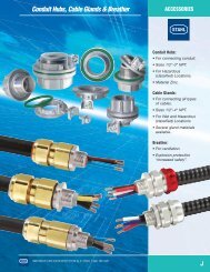
For entry hardware see pages C1, C3<br />
and C4<br />
• Can be combined to larger units<br />
Components:<br />
-Contact blocks<br />
-Pilot lights<br />
-Illuminated buttons<br />
-Control switches<br />
-Ammeters<br />
-Voltmeters<br />
For component data<br />
see pages F7-F14 and F31-33.<br />
INNOVATIVE EXPLOSION PROTECTION by R. STAHL 1-800-782-4357<br />
F16
CONTROLS<br />
8146 Series Control Stations<br />
IN FIBERGLASS REINFORCED POLYESTER (FRP)<br />
8082<br />
Control Block with actuators<br />
7/16"/o.d. 38mm<br />
Typical Panel Configurations<br />
8010<br />
LED Pilot Light<br />
8082/8010<br />
Illuminated Pushbutton<br />
ENCLOSURE DIMENSIONS PANEL CONFIGURATIONS CATALOG NUMBER<br />
SIZE<br />
Inches<br />
mm<br />
Panel configurations<br />
Maximum quantity of components such as;<br />
Contact Blocks 8082, Pilot Lights 8010,<br />
and Illuminated Pushbuttons 8082/8010.<br />
3 a b c<br />
4.43" 4.43" 3.58"<br />
112 mm 112 mm 91mm<br />
Side facing down<br />
4 a b c<br />
6.69" 4.43" 3.58"<br />
170 mm 112 mm 91mm<br />
Fig. 3.1<br />
A<br />
Fig. 4.1 Fig.4.2 Fig. 4.3<br />
8146/5031-3❒<br />
8146/5041-3❒<br />
Side facing down<br />
5 a b c<br />
6.69" 6.69" 3.58"<br />
170 mm 170 mm 91mm<br />
A A D<br />
Fig. 5.1 Fig.5.2 Fig. 5.3 Fig. 5.4<br />
8146/5051-3❒<br />
Side facing down<br />
6 a b c<br />
8.94" 6.69" 3.58"<br />
227 mm 170 mm 91mm<br />
Side facing down<br />
Add to catalog number:<br />
A A D D<br />
Fig. 6.1 Fig.6.2 Fig. 6.3 Fig. 6.4<br />
A A D D<br />
Specify side facing down A or D (see above)<br />
8146/5061-3❒<br />
For dimensional information see page F22<br />
F17<br />
INNOVATIVE EXPLOSION PROTECTION by R. STAHL 1-800-782-4357
8146 Series Control Stations<br />
CONTROLS<br />
Typical Panel Configurations<br />
IN FIBERGLASS REINFORCED POLYESTER (FRP)<br />
ENCLOSURE DIMENSIONS PANEL CONFIGURATIONS CATALOG NUMBER<br />
SIZE<br />
Inches<br />
mm<br />
Panel configurations<br />
Maximum quantity of components such as;<br />
Contact Blocks 8082, Pilot Lights 8010,<br />
and Illuminated Pushbuttons 8082/8010.<br />
7 a b c<br />
13.41" 6.69" 3.58"<br />
340 mm 170 mm 91 mm<br />
Fig. 7.1 Fig. 7.2<br />
8146/5071-3❒<br />
Side facing down<br />
D<br />
Fig. 7.3 Fig. 7.4<br />
D<br />
Side facing down<br />
A<br />
A<br />
8 a b c<br />
13.41" 13.41" 3.58"<br />
340 mm 340 mm 91 mm<br />
Fig. 8.1 Fig. 8.2<br />
8146/5081-3❒<br />
Side facing down<br />
D<br />
D<br />
9 a b c<br />
26.83" 13.41" 3.58"<br />
680 mm 340 mm 91 mm<br />
Fig. 9.1 Fig. 9.2<br />
8146/5091-3❒<br />
Side facing down<br />
A<br />
A<br />
Fig. 9.3<br />
Side facing down<br />
Add to catalog number:<br />
For dimensional information see page F22<br />
Specify side facing down A or D (see above)<br />
D<br />
INNOVATIVE EXPLOSION PROTECTION by R. STAHL 1-800-782-4357<br />
F18
CONTROLS<br />
8146 Series Control Stations<br />
IN FIBERGLASS REINFORCED POLYESTER (FRP)<br />
Emergency<br />
STOP (Jumbo)<br />
8082<br />
Contact Blocks with Double<br />
Momentary Pushbutton<br />
Typical Panel Configurations<br />
8008<br />
Control Switches<br />
8405<br />
Ammeter<br />
ENCLOSURE DIMENSIONS PANEL CONFIGURATIONS CATALOG NUMBER<br />
SIZE<br />
Inches<br />
mm<br />
Panel configurations<br />
Maximum quantity of components such as;<br />
Contact Blocks 8082, Pilot Lights 8010, Illuminated<br />
Pushbuttons 8082/8010, Control Switches 8008<br />
and Ammeters 8405.<br />
3 a b c<br />
4.43" 4.43" 3.58"<br />
112 mm 112 mm 91 mm<br />
Side facing down<br />
4 a b c<br />
6.69" 4.43" 3.58"<br />
170 mm 112 mm 91 mm<br />
Fig. 3.2 Fig. 3.3 Fig. 3.4<br />
A A A<br />
Fig. 4.4 Fig.4.5 Fig. 4.6 Fig. 4.7<br />
8146/5031-3❒<br />
8146/5041-3❒<br />
Side facing down<br />
A A D D<br />
5 a b c<br />
6.69" 6.69" 3.58"<br />
170 mm 170 mm 91 mm<br />
Fig. 5.5<br />
Fig.5.6<br />
8146/5051-3❒<br />
Side facing down<br />
D<br />
D<br />
Fig. 6.5 Fig. 6.6<br />
8146/5061-3❒<br />
6 a b c<br />
8.94" 6.69" 3.58"<br />
227 mm 170 mm 91 mm<br />
Side facing down<br />
A<br />
A<br />
Add to catalog number:<br />
Specify side facing down A or D (see above)<br />
For dimensional information see page F22<br />
F19<br />
INNOVATIVE EXPLOSION PROTECTION by R. STAHL 1-800-782-4357
8146 Series Control Stations<br />
CONTROLS<br />
Typical Panel Configurations<br />
IN FIBERGLASS REINFORCED POLYESTER (FRP)<br />
ENCLOSURE DIMENSIONS PANEL CONFIGURATIONS CATALOG NUMBER<br />
SIZE<br />
Inches<br />
mm<br />
Panel configurations<br />
Maximum quantity of components such as;<br />
Contact Blocks 8082, Pilot Lights 8010, Illuminated<br />
Pushbuttons 8082/8010, Control Switches 8008<br />
and Ammeters 8405.<br />
7 a b c<br />
13.41" 6.69" 3.58"<br />
340 mm 170 mm 91 mm<br />
Fig. 7.5<br />
8146/5071-3❒<br />
Side facing down<br />
D<br />
Fig. 7.6 Fig. 7.7<br />
Side facing down<br />
A<br />
A<br />
8 a b c<br />
13.41" 13.41" 3.58"<br />
340 mm 340 mm 91 mm<br />
Fig. 8.4 Fig. 8.5<br />
8146/5081-3❒<br />
Side facing down<br />
D<br />
D<br />
9 a b c<br />
26.83" 13.41" 3.58"<br />
680 mm 340 mm 91mm<br />
Fig. 9.4<br />
8146/5091-3❒<br />
Side facing down<br />
D<br />
Fig. 9.5<br />
Side facing down<br />
Add to catalog number:<br />
For dimensional information see page F22<br />
Specify side facing down A or D (see above)<br />
D<br />
INNOVATIVE EXPLOSION PROTECTION by R. STAHL 1-800-782-4357<br />
F20
CONTROLS<br />
8146 Series Control Stations<br />
PARTS AND ACCESSORIES<br />
ILLUSTRATION/DESCRIPTION<br />
CATALOG NUMBER<br />
ILLUSTRATION/DESCRIPTION<br />
CATALOG NUMBER<br />
Brass Plates<br />
for Flange<br />
Plates<br />
Flange<br />
Plates<br />
Size 1<br />
in FRP<br />
To bond metal cable glands<br />
for 8146<br />
Flange<br />
Size<br />
1 81 460 10 55 0<br />
2 81 460 33 55 0<br />
3 81 460 54 55 0<br />
Brass Plates<br />
for Enclosures<br />
without Flange<br />
Side<br />
Plates 8146/•03• C/D 81 460 17 55 0<br />
8146/•04• A/B 81 460 17 55 0<br />
C/D 81 460 43 55 0<br />
8146/•05• A/B 81 460 11 55 0<br />
C/D 81 460 22 55 0<br />
8146/•06• A/B 81 460 22 55 0<br />
C/D 81 460 16 55 0<br />
8146/•071 A/B 81 460 22 55 0<br />
C/D 81 460 23 55 0<br />
8146/•073 & A/B 81 460 39 55 0<br />
8146/•075 C/D 81 460 42 55 0<br />
8146/•S71 A/B 81 460 11 55 0<br />
C/D 81 460 31 55 0<br />
8146/•S73 A/B 81 460 38 55 0<br />
C/D 81 460 41 55 0<br />
8146/.081 A/B 81 460 23 55 0<br />
C/D 81 460 31 55 0<br />
8146/•083 & A/B 81 460 40 55 0<br />
8146/•085 & C/D 81 460 41 55 0<br />
8146/•086<br />
8146/•091 A/B 81 460 30 55 0<br />
C1/D1 81 460 10 55 0<br />
C2/D2 81 460 31 55 0<br />
Flange<br />
Plates<br />
Size 2<br />
Flange<br />
Plates<br />
Size 3<br />
Coupling<br />
Frames<br />
Versions<br />
0.11" 2,8mm thick 81 460 01 49 0<br />
0.23" 5,8mm thick 81 460 04 49 0<br />
For Mounting on:<br />
Enclosure Sides<br />
8146/•051/•052 C/D<br />
8146/•061/•062 A/B/C/D<br />
8146/•071/•072 A/B/C/D<br />
8146/•S71 C/D<br />
8146/•08/•082 A/B/C/D<br />
8146/•091/•092 A/B/C/D<br />
0.11" 2,8mm thick 81 460 05 49 0<br />
0.23" 5,8mm thick 81 460 06 49 0<br />
For Mounting on:<br />
Enclosure Sides<br />
8146/•073/•075 C/D<br />
8146/•S73 C/D<br />
8146/•083/•085/•86 A/B/C/D<br />
8146/•093/•095 A/B/C/D<br />
0.11" 2,8mm thick 81 460 10 49 0<br />
0.23" 5,8mm thick 81 460 11 49 0<br />
For Mounting on:<br />
Enclosure Sides<br />
8146/•073/•075 A/B<br />
Size 0 2.68" x 2.68" 81 460 03 10 0<br />
(68 mm x 68 mm)<br />
Size 1 5.04" x 2.68" 81 460 01 10 0<br />
(128 mm x 68 mm)<br />
Size 2 10.47" x 4.96" 81 460 04 10 0<br />
(266 mm x 126 mm)<br />
Size 3 4.96" x 4.96" 81 460 11 10 0<br />
(126 mm x 126 mm)<br />
8146/•093 & A/B 81 460 41 55 0<br />
8146/•095 C1/D1 81 460 40 55 0<br />
C2/D2 81 460 41 55 0<br />
Flange-enclosure 81 460 32 55 0<br />
Entry Hubs<br />
8166/11 mounted<br />
(see page C1 and C4)<br />
8166/11 part only<br />
(see page J1)<br />
F21<br />
INNOVATIVE EXPLOSION PROTECTION by R. STAHL 1-800-782-4357
8146 Series Control Stations<br />
CONTROLS<br />
DIMENSIONS<br />
.35"<br />
9mm<br />
.28"<br />
7mm<br />
A<br />
C<br />
D<br />
3.70"<br />
94mm<br />
4.43"<br />
112.5mm<br />
R6<br />
B<br />
.28"<br />
7mm<br />
2.36"<br />
60mm<br />
.63"<br />
16mm<br />
3.58"<br />
91mm<br />
A<br />
.28"<br />
7mm<br />
R6<br />
C<br />
.35"<br />
9mm<br />
D<br />
4.65"<br />
118mm<br />
6.69"<br />
170mm<br />
.28"<br />
7mm<br />
B<br />
3.70"<br />
94mm<br />
4.43"<br />
112.5mm<br />
.63"<br />
16mm<br />
3.58"<br />
91mm<br />
A<br />
.28"<br />
C 7mm<br />
R6<br />
D<br />
5.98"<br />
152mm<br />
6.69"<br />
170mm<br />
.35"<br />
9mm<br />
B<br />
.28"<br />
7mm<br />
4.65"<br />
118mm<br />
.63"<br />
16mm<br />
d<br />
8146/5031<br />
8.94"<br />
227mm<br />
C<br />
8146/5041<br />
C<br />
8146/505•<br />
6.69"<br />
170mm<br />
A<br />
R6<br />
.28" D .35"<br />
7mm 9mm<br />
6.89"<br />
175mm<br />
5.98"<br />
152mm<br />
B<br />
.28"<br />
7mm<br />
8146/506•<br />
.63"<br />
16mm<br />
d<br />
6.69"<br />
170mm<br />
A<br />
R6<br />
D<br />
.28"<br />
7mm 11.36"<br />
288.5mm<br />
13.41"<br />
340.5mm<br />
.35"<br />
9mm<br />
8146/507•<br />
B<br />
5.98"<br />
152mm<br />
.28"<br />
7mm<br />
.63"<br />
16mm<br />
d<br />
6.69"<br />
170mm<br />
A<br />
13.41"<br />
340.5mm<br />
C<br />
R6<br />
.28"<br />
7mm<br />
B<br />
4.65"<br />
118mm<br />
C<br />
.28"<br />
7mm<br />
R6<br />
.35"<br />
9mm<br />
D<br />
12.70"<br />
322.5mm<br />
8146/5S7•<br />
.28"<br />
7mm<br />
Flange option: Add to overall dimensions.<br />
Flange Thickness<br />
.35"<br />
9mm<br />
Dimension F<br />
0.11" 2.8mm 0.27" 7mm<br />
0.23" 5.8mm 0.39" 10mm<br />
.63"<br />
16mm<br />
d<br />
A<br />
D<br />
12.70"<br />
322.5mm<br />
13.41"<br />
340.5mm<br />
B<br />
.28"<br />
7mm<br />
11.36"<br />
288.5mm<br />
8146/508•<br />
d<br />
.63"<br />
16mm<br />
F<br />
Available Enclosure Depth (d)<br />
.35"<br />
9mm<br />
C<br />
11.36"<br />
288.5mm<br />
.28"<br />
7mm<br />
Enclosure 1 2 3 4 5 6<br />
Sizes 3.58" 5.16" 5.91" 6.73" 7.48" 9.06"<br />
91mm 131mm 150mm 171mm 190mm 230mm<br />
8146/503• x - - - - -<br />
8146/504• x - - - - -<br />
8146/505• x x - - - -<br />
8146/506• x x - - - -<br />
8146/507• x x x - x -<br />
8146/5S7• x - x - - -<br />
8146/508• x x x x x x<br />
8146/509• x x x - x -<br />
X indicates depths available.<br />
A<br />
R6<br />
11.36"<br />
288.5mm<br />
D<br />
2.01"<br />
52.5mm<br />
8146/509•<br />
26.83"<br />
681.5mm<br />
B<br />
12.70"<br />
322.5mm<br />
13.41"<br />
340.5mm<br />
d<br />
.63"<br />
16mm<br />
INNOVATIVE EXPLOSION PROTECTION by R. STAHL 1-800-782-4357<br />
F22
CONTROLS<br />
Notes<br />
F23<br />
INNOVATIVE EXPLOSION PROTECTION by R. STAHL 1-800-782-4357
8125 Series<br />
CONTROLS<br />
CONTROL STATION IN SHEET STEEL OR STAINLESS STEEL<br />
CLASSIFICATIONS<br />
NEC- Class I, Zones 1 & 2 AEx de II C T6<br />
Class I, Division 2, Groups A,B,C,D<br />
Class II, Division 2, Groups F,G<br />
Class III<br />
Enclosure Type:<br />
stainless steel version<br />
3, 4 & 4X; IP66,<br />
carbon steel version, painted<br />
3 & 4; IP66,<br />
File No. E182378<br />
CEC- Class I, Zones 1 & 2 Ex de II T6<br />
Class I, Division 2, Groups A,B,C,D<br />
Class II, Divisions 1 & 2, Groups E,F,G<br />
Class III<br />
CSA ENCLOSURES<br />
stainless steel version<br />
3, 4 & 4X; IP66<br />
carbon steel version, painted<br />
3 & 4; IP66<br />
File No. LR 99480<br />
II 2G Ex ed IIC T6, IP66<br />
PTB 01 ATEX 1001<br />
II 2D IP6X, T80˚C, T95˚C or T130˚C<br />
LCIE 03 ATEX 6292<br />
Special Ambient Temperature Range:*<br />
+55˚C (+131˚F) Max.<br />
–55˚C (–67˚F) Min.<br />
Consult Factory<br />
*<br />
Features:<br />
8125 series control stations are designed<br />
to incorporate control and display devices.<br />
The number of units installed depends<br />
on the control station size and the space<br />
required to fit each device.<br />
• Enclosures in galvanized sheet steel<br />
or 316 stainless steel<br />
• 7 basic enclosure sizes<br />
• Different enclosure depths<br />
• Options:<br />
- Flanges<br />
- Cover Hinges<br />
• Enclosures can be coupled together<br />
For entry hardware see pages C15, C17 &<br />
C18<br />
Components:<br />
- Contact blocks<br />
- Pilot lights<br />
- Illuminated buttons<br />
- Control switches<br />
- Ammeters<br />
- Voltmeters<br />
For component data<br />
see pages F7-F14 and F31-33.<br />
INNOVATIVE EXPLOSION PROTECTION by R. STAHL 1-800-782-4357<br />
5/14/01<br />
F24
CONTROLS<br />
8125 Series Control Stations<br />
IN CARBON STEEL OR STAINLESS STEEL<br />
8082<br />
Control Unit with actuators<br />
7/16" /o.d. 38mm<br />
8010<br />
LED Pilot Light<br />
8082/8010<br />
Illuminated Pushbutton<br />
Typical Panel Configurations<br />
ENCLOSURE DIMENSIONS PANEL CONFIGURATIONS CATALOG NUMBER<br />
SIZE<br />
Inches<br />
mm<br />
Panel configurations<br />
Maximum quantity of components such as;<br />
Contact Blocks 8082, Pilot Lights 8010,<br />
and Illuminated Pushbuttons 8082/8010.<br />
4 a b c<br />
6.95" 4.58" 3.58"<br />
176 mm 116 mm 91 mm<br />
Side facing down<br />
5 a b c<br />
6.95" 6.95" 3.58"<br />
176 mm 176 mm 91 mm<br />
Fig. 4.1<br />
A<br />
Fig. 5.1 Fig.5.2 Fig. 5.3 Fig. 5.4<br />
8125/5041-❒❒<br />
8125/5051-❒❒<br />
Side facing down<br />
6 a b c<br />
9.29" 6.95" 3.58"<br />
236 mm 176 mm 91 mm<br />
A A D D<br />
Fig. 6.1 Fig. 6.2 Fig. 6.3 Fig. 6.4<br />
8125/5061-❒❒<br />
Side facing down<br />
A A D D<br />
7 a b c<br />
14.17" 6.95" 3.58"<br />
360 mm 176 mm 91mm<br />
Side facing down<br />
Fig. 7.1 Fig. 7.2<br />
D<br />
D<br />
8125/5071-❒❒<br />
Enclosure material:<br />
sheet steel, painted<br />
stainless steel<br />
1<br />
2<br />
Add to catalog number:<br />
Specify side facing down A or D (see above)<br />
For dimensional information see page F30<br />
F25<br />
5/14/01<br />
INNOVATIVE EXPLOSION PROTECTION by R. STAHL 1-800-782-4357
8125 Series Control Stations<br />
CONTROLS<br />
IN CARBON STEEL OR STAINLESS STEEL<br />
Typical Panel Configurations<br />
ENCLOSURE DIMENSIONS PANEL CONFIGURATIONS CATALOG NUMBER<br />
SIZE<br />
Inches<br />
mm<br />
Panel configurations<br />
Maximum quantity of components such as;<br />
Contact Blocks 8082, Pilot Lights 8010,<br />
and Illuminated Pushbuttons 8082/8010.<br />
7 a b c<br />
14.17" 6.95" 3.58"<br />
360 mm 176 mm 91mm<br />
Fig. 7.3 Fig. 7.4<br />
8125/5071-❒❒<br />
Side facing down<br />
A<br />
A<br />
8 a b c<br />
14.17" 14.17" 3.58"<br />
360 mm 360 mm 91mm<br />
Fig. 8.1 Fig. 8.2<br />
8125/5081-❒❒<br />
Side facing down<br />
D<br />
D<br />
9 a b c<br />
28.62" 14.17" 3.58"<br />
727 mm 360 mm 91mm<br />
Fig. 9.1 Fig. 9.2<br />
8125/5091-❒❒<br />
Side facing down<br />
A<br />
A<br />
Fig. 9.3<br />
Side facing down<br />
D<br />
Enclosure material:<br />
sheet steel, painted<br />
stainless steel<br />
1<br />
2<br />
Add to catalog number:<br />
Specify side facing down A or D (see above)<br />
For dimensional information see page F30<br />
INNOVATIVE EXPLOSION PROTECTION by R. STAHL 1-800-782-4357<br />
F26
CONTROLS<br />
8125 Series<br />
IN CARBON STEEL OR STAINLESS STEEL<br />
Emergency<br />
STOP (Jumbo)<br />
8082<br />
Contact Blocks with Double<br />
Momentary Pushbutton<br />
Typical Panel Configurations<br />
8008<br />
Control Switches<br />
8405<br />
Ammeter<br />
ENCLOSURE DIMENSIONS PANEL CONFIGURATIONS CATALOG NUMBER<br />
SIZE<br />
Inches<br />
mm<br />
Panel configurations<br />
Maximum quantity of components such as;<br />
Contact Blocks 8082, Pilot Lights 8010, Illuminated<br />
Pushbuttons 8082/8010, Control Switches 8008<br />
and Ammeters 8405.<br />
4 a b c<br />
6.95" 4.58" 3.58"<br />
176 mm 116 mm 91 mm<br />
Side facing down<br />
5 a b c<br />
6.95" 6.95" 3.58"<br />
176 mm 176 mm 91mm<br />
Fig. 4.4 Fig. 4.5 Fig. 4.6 Fig. 4.7<br />
A A D D<br />
Fig. 5.5 Fig. 5.6<br />
8125/5041-❒❒<br />
8125/5051-❒❒<br />
Side facing down<br />
D<br />
D<br />
6 a b c<br />
9.29" 6.95" 3.58"<br />
236 mm 176 mm 91 mm<br />
Fig. 6.5 Fig. 6.6<br />
8125/5061-❒❒<br />
Side facing down<br />
7 a b c<br />
14.17" 6.95" 3.58"<br />
360 mm 176 mm 91mm<br />
Side facing down<br />
A<br />
Fig. 7.5<br />
A<br />
D<br />
8125/5071-❒❒<br />
Enclosure material:<br />
sheet steel, painted<br />
stainless steel<br />
1<br />
2<br />
Add to catalog number:<br />
Specify side facing down A or D (see above)<br />
For dimensional information see page F30<br />
F27<br />
INNOVATIVE EXPLOSION PROTECTION by R. STAHL 1-800-782-4357
8125 Series<br />
CONTROLS<br />
Typical Panel Configurations<br />
IN CARBON STEEL OR STAINLESS STEEL<br />
ENCLOSURE DIMENSIONS PANEL CONFIGURATIONS CATALOG NUMBER<br />
SIZE<br />
Inches<br />
mm<br />
Panel configurations<br />
Maximum quantity of components such as;<br />
Contact Blocks 8082, Pilot Lights 8010, Illuminated<br />
Pushbuttons 8082/8010, Control Switches 8008<br />
and Ammeters 8405.<br />
7 a b c<br />
14.17" 6.95" 3.58"<br />
360 mm 176 mm 91 mm<br />
Fig. 7.6 Fig. 7.7 8125/5071-❒❒<br />
Side facing down<br />
A<br />
A<br />
8 a b c<br />
14.17" 14.17" 3.58"<br />
360 mm 360 mm 91 mm<br />
Fig. 8.4 Fig. 8.5<br />
8125/5081-❒❒<br />
Side facing down<br />
D<br />
D<br />
9 a b c<br />
28.62" 14.17" 3.58"<br />
727 mm 360 mm 91 mm<br />
Fig. 9.4<br />
8125/5091-❒❒<br />
Side facing down<br />
D<br />
Fig. 9.5<br />
Side facing down<br />
D<br />
Enclosure material:<br />
sheet steel, painted<br />
stainless steel<br />
1<br />
2<br />
Add to catalog number:<br />
For dimensional information see page F30<br />
Specify side facing down A or D (see above)<br />
INNOVATIVE EXPLOSION PROTECTION by R. STAHL 1-800-782-4357<br />
F28
CONTROLS<br />
8125 Series Control Stations<br />
PARTS AND ACCESSORIES<br />
DESIGNATION ILLUSTRATION DESCRIPTION CATALOG NUMBER<br />
Flange 5" x 2.7" x 0.2"<br />
Plate<br />
(128 x 68 x 5 mm)<br />
Size 1 carbon steel 81 250 01 49 0<br />
316 stainless steel 81 259 02 49 0<br />
Can be fitted in<br />
Enclosures Sides<br />
8125/•051 A/B/C/D<br />
8125/•061 A/B/C/D<br />
8125/•071 A/B/C/D<br />
8125/•S71 C/D<br />
8125/•081 A/B/C/D<br />
Flange 10.5" x 5" x 0.2"<br />
Plate<br />
(266 x 128 x 5 mm)<br />
Size 2 carbon steel 81 250 02 49 0<br />
316 stainless steel 81 259 04 49 0<br />
Can be fitted in<br />
Enclosures Sides<br />
8125/•063 C/D<br />
8125/•073 C/D<br />
8125/•083 /•085 A/B/C/D<br />
8125/•093 /•095 A/B/C/D<br />
Flange 5" x 5" x 0.2"<br />
Plate<br />
(126 x 126 x 5 mm)<br />
Size 3 carbon steel 81 250 03 49 0<br />
316 stainless steel 81 259 06 49 0<br />
Can be fitted in<br />
Enclosures Sides<br />
8125/•073 A/B<br />
Flange 13.86" x 6.1" x 0.2"<br />
Plate<br />
(352 x 155 x 5 mm)<br />
Size 4 carbon steel 81 250 04 49 0<br />
316 stainless steel 81 259 08 49 0<br />
Can be fitted in<br />
Enclosures Sides<br />
8125/•085 A/B/C/D<br />
8125/•095 A/B/C/D<br />
Coupling Frames<br />
Cover Hinges<br />
Frame Sizes<br />
0 2.68" x 2.68" 81 460 03 10 0<br />
(68 mm x 68 mm)<br />
1 5.04" x 2.68" 81 460 01 10 0<br />
(128 mm x 68 mm)<br />
2 10.47" x 4.96" 81 460 04 10 0<br />
(266 mm x 126 mm)<br />
3 4.96" x 4.96" 81 460 11 10 0<br />
(126 mm x 126 mm)<br />
4 13.86" x 6.1" 81 250 04 10 0<br />
(352 mm x 155 mm)<br />
8125 for retrofitting to enclosure<br />
Kit consists of:<br />
2 hinges 81 258 02 29 0<br />
3 hinges 81 258 03 29 0<br />
Entry Hubs<br />
8166/11 mounted<br />
(see page C15 and C18)<br />
8166/11 part only<br />
(see page J1)<br />
For Entry information see pages C15, 17 & 18.<br />
F29<br />
INNOVATIVE EXPLOSION PROTECTION by R. STAHL 1-800-782-4357
8403 Series Ammeters & 8404 Series Voltmeters<br />
CONTROLS<br />
Selection Table<br />
Version Ammeter Measuring Catalog Number<br />
Voltmeter Range Type no. Assembly<br />
Overload for individual (code for<br />
Scale order installation)<br />
8403<br />
Ammeter<br />
❑ 72 mm 2.83"<br />
Slide-in Scale<br />
8404<br />
Voltmeter<br />
❑ 72 mm 2.83"<br />
Bezel<br />
Dimensions<br />
direct measuring 0 -20mA 2 times 8403/2-0.02/0.04 82/0.02/0.04<br />
0 -1/2A 8403/2-1/2 82/1/2<br />
0 -4/8A 8403/2-4/8 82/4/8<br />
0 -10/20A 8403/2-10/20 82/10/20<br />
0 -15/30A 8403/2-15/30 82/15/30<br />
0 -25/50A 8403/2-25/50 82/25/50<br />
for current sec 1A 8403/2-1 82/1<br />
transformers sec 5A 2 and 5 times overload 8403/2-5 82/5<br />
}<br />
Slide-in scale for 2 times overload or<br />
for ammeters for 5 times overload<br />
indirect<br />
measuring ranges<br />
measuring 0 … 1; 5; 10; 15; 20; State measuring<br />
25; 30; 40; 50; 60; 75; 100; range<br />
150; 200; 250; 300; 500<br />
direct measuring 0 -10V 8404/2-10 79/10<br />
0 -100V 8404/2-100 79/100<br />
0 -120V 8404/2-120 79/120<br />
0 -150V 8404/2-150 79/150<br />
0 -250V 8404/2-250 79/250<br />
0 -500V 8404/2-500 79/500<br />
Bezel 2.83" x 2.83" 72mm x 72mm 86 038 02 58 7 145<br />
(for ammeter 8403 and<br />
for voltmeter 8404)<br />
APPROVALS<br />
Certification Pending<br />
CERTIFIED - FILE LR99480<br />
PTB 01 ATEX 2158 U<br />
Ammeter<br />
The 8403 Series ammeters are used to measure<br />
current of a motor supply circuit in a potentially<br />
explosive atmosphere.<br />
They are moving iron instruments with an<br />
accuracy class 2.5.<br />
They are available for direct measuring<br />
up to 25 Amps, and for indirect measuring<br />
in conjunction with a current transformer<br />
either for 1 Amp or 5 Amp secondary current.<br />
For indirect measuring slide-in scales are<br />
available. Ammeter/slide-in scale must have<br />
the same ratio that the CT has. (CTs are not<br />
supplied).<br />
A red pointer can be manually adjusted<br />
for quick visual comparison of the actual<br />
value with the set value.<br />
Voltmeter<br />
The 8404 Series of voltmeters are used to<br />
measure voltage of a motor supply circuit in<br />
a potentially explosive atmosphere.<br />
They are moving iron instruments with an<br />
accuracy class 2.5.<br />
A red pointer can be manually adjusted<br />
for quick visual comparison of the actual<br />
value with the set value.<br />
Both 8403 Ammeters and 8404 Voltmeters<br />
are suitable to mount into increased safety<br />
enclosures Series 8125 or 8146.<br />
Slide-in scale for<br />
ammeters with CT<br />
8403 Ammeter<br />
and Voltmeter<br />
8404 with bezel<br />
assembly 145<br />
8403 Ammeter<br />
Bezel Assembly 145<br />
INNOVATIVE EXPLOSION PROTECTION by R. STAHL 1-800-782-4357<br />
F32
8125 Series Control Stations<br />
CONTROLS<br />
DIMENSIONS<br />
6.95"<br />
176.5mm<br />
5.37"<br />
136.5mm<br />
.98"<br />
25mm<br />
C<br />
6.95"<br />
176.5mm<br />
5.37"<br />
136.5mm<br />
.98"<br />
25mm<br />
C<br />
.98"<br />
25mm<br />
7.7"<br />
199mm<br />
C<br />
9.3"<br />
237mm<br />
6.63"<br />
168.5mm<br />
6"<br />
152.5mm<br />
4.59"<br />
116.5mm<br />
A<br />
D<br />
B<br />
.28"<br />
7mm<br />
.22"<br />
5.5mm<br />
.39"<br />
10mm<br />
3.58"<br />
91mm<br />
7.00"<br />
228.5mm<br />
8.37"<br />
212.5mm<br />
6.95"<br />
176.5mm<br />
A<br />
D<br />
B<br />
.28"<br />
7mm<br />
.22"<br />
5.5mm 10mm<br />
.39"<br />
3.58"<br />
91mm<br />
9"<br />
229mm<br />
8.4"<br />
213mm<br />
6.95"<br />
176.5mm<br />
A<br />
D<br />
B<br />
.28"<br />
7mm<br />
.22"<br />
5.5mm<br />
.39"<br />
10mm<br />
d<br />
8125/5041<br />
8125/5051<br />
8125/506•<br />
.28"<br />
7mm<br />
C<br />
C<br />
.28"<br />
7mm<br />
A<br />
B<br />
6.95"<br />
176.5mm<br />
8.37"<br />
212.5mm<br />
9.00"<br />
228.5mm<br />
A<br />
14.17"<br />
360mm<br />
B<br />
15.59"<br />
396mm<br />
16.22"<br />
412mm<br />
Available Enclosure Depth (d)<br />
1 3 5 6<br />
Enclosure<br />
Sizes 3.58" 5.91" 7.48" 9.06"<br />
91mm 150mm 190mm 230mm<br />
8125/504• x - - -<br />
8125/505• x - - -<br />
8125/506• x x - -<br />
8125/507• x x - -<br />
8125/508• x x x x<br />
8125/509• x x x -<br />
0.47"<br />
12mm<br />
D<br />
12.60"<br />
320mm<br />
.98"<br />
25mm<br />
14.17"<br />
360mm<br />
.22"<br />
5.5mm<br />
d<br />
.39"<br />
10mm<br />
D<br />
12.60"<br />
320mm<br />
.98"<br />
25mm<br />
14.17"<br />
360mm<br />
.22"<br />
5.5mm<br />
d<br />
.39"<br />
10mm<br />
8125/507•<br />
8125/508•<br />
.28"<br />
7mm<br />
C<br />
A<br />
B<br />
14.17"<br />
360mm<br />
15.59"<br />
396mm<br />
16.22"<br />
412mm<br />
27.05"<br />
687mm<br />
D<br />
28.62"<br />
727mm<br />
.98"<br />
25mm<br />
.22"<br />
5.5mm<br />
d<br />
.39"<br />
10mm<br />
8125/509•<br />
Flange option:<br />
Add to overall<br />
dimensions.<br />
INNOVATIVE EXPLOSION PROTECTION by R. STAHL 1-800-782-4357<br />
F30
CONTROLS<br />
8560 Series, Fuses<br />
Ordering Information<br />
SMALL FUSE BASES<br />
quick<br />
acting<br />
Rated Current<br />
Catalog Number<br />
32 mA 8560/51-4023<br />
50 mA 8560/51-4033<br />
63 mA 8560/51-4043<br />
CLASSIFICATIONS<br />
NEC-CEC<br />
Class I, Zones 1 & 2<br />
AEx/Ex me II T*<br />
Class I, Division 2, Groups A,B,C,D<br />
File No. EI82378<br />
II 2 G Ex me II T*<br />
PTB 99 ATEX 2158U<br />
Max. Voltage 250 AC/DC<br />
Ambient Temperature Range:<br />
+70˚C (158˚F) Max.<br />
–50˚C (–58˚F) Min.<br />
Ambient Temp. Current Temp. Classes<br />
Ta ≤56˚ C ≤4.0 A T6<br />
Ta ≤70˚ C ≤4.0 A T5<br />
Ta ≤46˚ C ≤5.0 A T5<br />
Ta ≤70˚ C ≤6.3 A T4<br />
FEATURES:<br />
• The small fuse base 8560 Series is<br />
designed for 250V AC/DC for low<br />
amperage circuits from 32mA to 1.25A in<br />
quick-acting characteristic and from 2A to<br />
6.3A in time-lag characteristic.<br />
• The fuse base is for quick and easy<br />
snap-on mounting on DIN rails TS15,<br />
TS35 and TS32.<br />
• They need to be mounted into “increased<br />
safety” certified enclosures i.e. the STAHL<br />
Series 8125 or 8146<br />
Terminal or<br />
Control<br />
Enclosures.<br />
*<br />
without<br />
cover<br />
8560<br />
Small fuse bases<br />
Accessories<br />
Identification Label (self adhesive)<br />
Dimensions<br />
16.5 mm<br />
1.57"<br />
t (s)<br />
5<br />
10<br />
5<br />
2<br />
4<br />
10<br />
5<br />
45.5 mm<br />
1.79"<br />
42.5 mm<br />
1.67"<br />
40 mm<br />
1.57"<br />
Time - current characteristics<br />
32 mA - 100 mA<br />
125 mA - 1.25 A<br />
Description<br />
t (s)<br />
5<br />
10<br />
5<br />
2<br />
4<br />
10<br />
5<br />
F1<br />
with<br />
cover<br />
Current/time characteristics for fuses<br />
quick-acting<br />
time<br />
lag<br />
42 mm<br />
1.65"<br />
80 mA 8560/51-4053<br />
100 mA 8560/51-4063<br />
125 mA 8560/51-4073<br />
160 mA 8560/51-4083<br />
200 mA 8560/51-4093<br />
250 mA 8560/51-4103<br />
315 mA 8560/51-4113<br />
400 mA 8560/51-4133<br />
500 mA 8560/51-4143<br />
630 mA 8560/51-4153<br />
800 mA 8560/51-4173<br />
1 A 8560/51-4183<br />
1.25 A 8560/51-4193<br />
2 A 8560/51-4222<br />
4 A 8560/51-4252<br />
6.3 A 8560/51-4272<br />
...<br />
F...<br />
time -lag<br />
Time - current characteristics<br />
2 A - 6.3 A<br />
18.5 mm<br />
0.73"<br />
2<br />
3<br />
10<br />
5<br />
2<br />
3<br />
10<br />
5<br />
2<br />
2<br />
10<br />
5<br />
2<br />
2<br />
10<br />
5<br />
2<br />
1<br />
10<br />
5<br />
2<br />
1<br />
10<br />
5<br />
2<br />
0<br />
10<br />
5<br />
2<br />
-1<br />
10<br />
5<br />
2<br />
0<br />
10<br />
5<br />
2<br />
-1<br />
10<br />
5<br />
2<br />
-2<br />
10<br />
5<br />
2<br />
-3<br />
10<br />
1 1.5 2 3 4 5 6 8<br />
1<br />
10<br />
1.5<br />
2 3 4 5 6 8<br />
rat<br />
2<br />
10<br />
2<br />
-2<br />
10<br />
5<br />
2<br />
-3<br />
10<br />
1 1.5 2 3 4 5 6 8<br />
1<br />
10<br />
1.5<br />
2 3 4 5 6 8<br />
rat<br />
2<br />
10<br />
F31<br />
INNOVATIVE EXPLOSION PROTECTION by R. STAHL 1-800-782-4357
CONTROLS<br />
Control Components<br />
Ordering Information<br />
8082 LOCKOUT TERMINAL<br />
DESCRIPTION<br />
CONTACT SYMBOL<br />
IEC<br />
NEMA<br />
INDIVIDUAL<br />
ORDER<br />
CATALOG NUMBER<br />
APPROVALS<br />
FILE No. E182378<br />
PTB 00 ATEX 1031U<br />
The lockout Terminal 8082/1-1-01 has one NC<br />
contact and is operated by the black lever. It is<br />
also lockable with a padlock.<br />
Each block is made of polyamide and designed<br />
to contain an internal explosion.<br />
The terminals are designed to increased<br />
safety “e” requirements.<br />
Lockout<br />
Terminal, 1 NC<br />
Technical Data<br />
Rated Voltage<br />
Continuous Current<br />
Terminals<br />
Mechanical Life<br />
Electrical Life<br />
Housing Material<br />
Contact Material<br />
Lowest Energy<br />
NEC/CEC IEC<br />
600VAC 500VAC<br />
10A<br />
6A<br />
12AWG 2.5mm 2<br />
≥ 10 6 operations<br />
≥ 10 6 operations<br />
polyamide<br />
silver plated<br />
50mA. @ 12VAC/DC*<br />
* For lower energy use gold plated contacts, available on request.<br />
8082/1-1-01<br />
F33<br />
INNOVATIVE EXPLOSION PROTECTION by R. STAHL 1-800-782-4357