Low Voltage 3-Phase Induction Motors Range 0.09 ... - RMS Industrial
Low Voltage 3-Phase Induction Motors Range 0.09 ... - RMS Industrial
Low Voltage 3-Phase Induction Motors Range 0.09 ... - RMS Industrial

You also want an ePaper? Increase the reach of your titles
YUMPU automatically turns print PDFs into web optimized ePapers that Google loves.
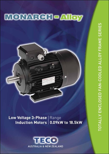
<strong>Low</strong> <strong>Voltage</strong> 3-<strong>Phase</strong><br />
<strong>Induction</strong> <strong>Motors</strong><br />
Alloy<br />
<strong>Range</strong><br />
<strong>0.09</strong>kW to 18.5kW<br />
Totally Enclosed Fan-Cooled alloy Frame sEries<br />
AUSTralia & NEW ZEaland
MONARCH - Alloy<br />
General Information<br />
MONARCH Alloy - Three <strong>Phase</strong> <strong>Induction</strong> <strong>Motors</strong><br />
are a range of high quality, Totally Enclosed Fan Cooled<br />
(TEFC), Squirrel Cage <strong>Induction</strong> motors, designed,<br />
manufactured and tested to the latest International and<br />
Australian Standards.<br />
Electrical Design and Standards<br />
Altitude<br />
Ambient<br />
• Designed for operation at an altitude up to 1000<br />
metres above sea level (please refer to TECO<br />
sales offices for higher altitudes).<br />
• <strong>Motors</strong> are designed to operate in ambient<br />
conditions of -20°C to +40°C as standard.<br />
Operation in adverse ambient conditions should<br />
be referred to TECO.<br />
Direction of Rotation<br />
• Standard rotation is clockwise when viewed<br />
from the drive end with the terminal marking<br />
corresponding to incoming line markings.<br />
Duty Rating<br />
• All motors have a maximum continuous duty<br />
rating of S1 to AS1359.101. Other duty ratings are<br />
available on request.<br />
Electric Supply<br />
• Stock motors are designed for operation on a<br />
380~415 Volt 3 phase 50 Hz supply and are also<br />
suitable for a 440~480 Volt 3 <strong>Phase</strong> 60 Hz supply.<br />
• <strong>Motors</strong> 3 kW and below are 380 - 415 Volt 50 Hz<br />
STAR connected and may also be reconnected<br />
to 240 Volt 3 phase 50 Hz DELTA configuration<br />
for use with single phase input Variable Speed<br />
Drives.<br />
• <strong>Motors</strong> 4 kW and larger are 380~415 [380 – 415]<br />
Volt 50 Hz DELTA connected.<br />
• <strong>Motors</strong> can be manufactured for other supply<br />
systems on a factory made to order basis or by<br />
local rewind / wind.<br />
MEPS (Minimum Efficiency Performance<br />
Standard) Performance<br />
• All motors, 0.75kW and larger meet or exceed<br />
the Minimum Efficiency level requirements<br />
of the Australian / New Zealand Standard<br />
“AS/NZS1359.5-2004” where applicable.<br />
Performance<br />
• <strong>Motors</strong> are designed to meet the performance<br />
requirements of Design N as per AS1359.41,<br />
normal torque for Direct On Line starting.<br />
• <strong>Motors</strong> are also suitable for other means of<br />
starting, depending on load characteristics,<br />
please refer to TECO.<br />
Standards<br />
• <strong>Motors</strong> are designed, manufactured and tested<br />
in accordance with AS1359, IEC60034, IEC60072<br />
with Quality Assurance to ISO9001.<br />
Stator and Windings<br />
• High grade insulated cold rolled electro magnetic<br />
steel laminations.<br />
• Standard insulation is Class F insulation (155°C).<br />
Windings are designed with a temperature rise<br />
of Class B (80°C) for long motor life and thermal<br />
reserve for abnormal conditions.<br />
Star / Delta Connection Diagram<br />
2 two<br />
AUSTralia & NEW ZEaland
MONARCH - Alloy<br />
Testing<br />
• In addition to a full program of tests during<br />
manufacture each motor is subjected to routine<br />
tests to AS1359 prior to despatch.<br />
Variable Speed Drive (VSD) suitability<br />
• <strong>Motors</strong> are suitable for VSD duty, subject to<br />
torque and speed limitations depending on the<br />
load characteristics and correct installation of<br />
motor and drive.<br />
Finish<br />
• The cooling fans are bi-directional and low noise<br />
as standard.<br />
• All castings are mechanically cleaned and degreased<br />
with aluminium components being<br />
primed externally.<br />
• Two finish coats of matt acrylic resin in finish<br />
colour Black is applied providing a good quality<br />
corrosion protected surface.<br />
Mechanical Design and Standards<br />
Balance<br />
• All rotors are dynamically balanced with a half<br />
key to Class N or better, in accordance with<br />
AS1359.114.<br />
Bearing and Lubrication System<br />
• <strong>Motors</strong> have a Ball / Ball bearing combination and<br />
are fitted with greased for life sealed bearings.<br />
• Shaft Oil seals are provided at each end on all<br />
motors to exclude the ingress of dust and water.<br />
Hardware<br />
• All hardware is electro zinc plated for better<br />
corrosion resistance.<br />
• Stainless steel hardware can be offered as<br />
an alternative, please contact TECO for the<br />
surcharge to provide this feature.<br />
Mounting<br />
<strong>Motors</strong> are available in the following mountings -<br />
• Foot mounted<br />
• Foot and Flange mounted<br />
Cooling System<br />
• Cooling is Totally Enclosed Fan Cooled (TEFC),<br />
with integrally cast cooling fins into the frame<br />
and is fitted with an external cooling fan (IC411)<br />
to AS1359.106.<br />
• Flange mounted<br />
• Foot and C Face mounted (B34A)<br />
• C Face mounted (B14A)<br />
• Pad Mounted (D71 – D160)<br />
Monarch Alloy Foot<br />
and Flange mount<br />
AUSTralia & NEW ZEaland<br />
three<br />
3
MONARCH - Alloy<br />
Motor Construction<br />
Terminal Box<br />
Frame size<br />
Frame<br />
D56 ~ D90 Aluminium<br />
alloy<br />
D100 ~<br />
D160<br />
Aluminium<br />
alloy<br />
Drive end<br />
endshield<br />
Aluminium<br />
alloy<br />
Cast Iron<br />
Non drive<br />
end<br />
endshield<br />
Cast Iron<br />
Cast Iron<br />
C face or<br />
D flange<br />
mount<br />
endshield<br />
Aluminium<br />
alloy<br />
Aluminium<br />
alloy<br />
• Terminal box as standard is top mounted on<br />
motor frame with all metal to metal joints<br />
provided with neoprene gaskets, this can be<br />
rotated to provide right hand or left hand side<br />
terminal box position.<br />
• Base – Lid surfaces are machined and fitted with<br />
one-piece neoprene gasket.<br />
• Castings are machined to close tolerances for<br />
accurate alignment and minimum vibration.<br />
• Terminal box can be rotated in 90° steps through<br />
360° for alternate cable entry orientations.<br />
• External cooling fan is polypropylene.<br />
• Fan cover is pressed steel.<br />
• Multi-mount frame construction, to enable the<br />
terminal box to be located in any position by<br />
repositioning the cast alloy motor feet, which are<br />
bolted to the frame.<br />
Popular Options Available<br />
Some available options in this range are as follows:<br />
• Airstream rated IC418<br />
• Anti-condensation heaters<br />
• Cooling Tower application<br />
Rating Plate<br />
• An anodised Aluminium rating plate containing<br />
all details as specified in AS1359.4 including<br />
bearing sizes is fitted to all motors.<br />
Rotor Assembly<br />
• High grade insulated cold rolled electro<br />
magnetic steel laminations.<br />
• Rotor cage is pressure die cast high<br />
conductivity aluminium with wafter<br />
blades and balance supports integrally<br />
cast onto the rotor endrings.<br />
• Double / non standard shaft extensions<br />
• Encoder / Tacho<br />
• Force cooling IC416<br />
• IP56, IP65 & IP66 enclosure<br />
• Multi-speed motors<br />
• Special paint systems / colours<br />
• Stainless steel fasteners<br />
• Others on request<br />
• The rotor is a press fit to<br />
the carbon steel shaft.<br />
Monarch Alloy Foot<br />
and C Face mount<br />
4<br />
four<br />
AUSTralia & NEW ZEaland
TYPICAL PERFORMANCE DATA<br />
MONARCH - Alloy<br />
MONARCH - Alloy FRAME TEFC THREE PHASE SQUIRREL CAGE INDUCTION MOTORS<br />
FRAME SIZES 56 - 160L (415V 50Hz)<br />
OUTPUT<br />
kW<br />
FULL<br />
LOAD<br />
RPM<br />
FRAME<br />
NO.<br />
FULL<br />
LOAD<br />
(%)<br />
EFFICIENCY POWER FACTOR CURRENT TORQUE INERTIA NOISE<br />
LEVEL WEIGHT<br />
3/4<br />
LOAD<br />
(%)<br />
1/2<br />
LOAD<br />
(%)<br />
FULL<br />
LOAD<br />
(%)<br />
3/4<br />
LOAD<br />
(%)<br />
1/2<br />
LOAD<br />
(%)<br />
FULL<br />
LOAD<br />
(A)<br />
LOCKED<br />
ROTOR<br />
(%)<br />
FULL<br />
LOAD<br />
N.m<br />
LOCKED<br />
ROTOR<br />
%FLT<br />
PULL<br />
UP<br />
%FLT<br />
BREAK-<br />
DOWN<br />
%FLT<br />
ROTOR<br />
J = GD 2 /4<br />
kg-m 2<br />
dB(A)<br />
footmount<br />
KGS<br />
2740 56 62.0 59.4 54.4 68.0 59.0 46.3 0.30 350 0.314 320 260 310 0.000170 70 3.2<br />
<strong>0.09</strong><br />
1350 56 58.0 54.5 50.0 61.0 55.0 43.7 0.35 320 0.637 290 280 280 0.000496 65 3.3<br />
2740 56 67.0 63.3 59.7 71.0 64.2 50.6 0.35 490 0.418 350 330 370 0.000219 70 3.8<br />
0.12<br />
1370 63 60.0 55.8 50.0 63.0 53.6 42.5 0.44 370 0.836 235 310 310 0.000537 65 4.3<br />
2740 63 69.0 68.5 66.1 75.0 71.3 56.6 0.53 370 0.627 225 210 250 0.000250 70 4.1<br />
0.18 1370 63 64.0 59.0 52.6 66.0 48.6 37.8 0.62 380 1.25 280 290 280 0.001 65 4.7<br />
920 71 59.0 55.0 46.0 54.4 45.6 36.6 0.78 320 1.87 250 220 380 0.00151 61 6.5<br />
2740 63 72.0 71.5 69.9 78.0 73.6 59.0 0.62 320 0.871 270 270 350 0.000312 70 4.8<br />
0.25 1370 71 67.0 65.5 64.0 68.0 62.1 48.2 0.76 280 1.74 225 200 220 0.001 65 5.8<br />
910 71 65.0 63.4 56.3 60.0 49.6 38.5 0.89 330 2.62 260 250 245 0.00186 61 7<br />
2740 71 73.5 70.7 66.1 80.0 69.8 56.4 0.91 445 1.29 335 280 240 0.001 75 6.1<br />
0.37 1370 71 69.5 66.9 62.1 72.0 61.4 48.3 1.07 380 6.30 245 2.05 230 0.001 70 7<br />
930 80 70.0 69.3 64.0 65.5 55.1 42.5 1.12 370 3.80 225 215 255 0.00381 63 9.4<br />
2780 71 75.5 73.0 70.8 82.0 70.0 56.8 1.29 570 6.52 345 340 325 0.001 75 7.2<br />
0.55 1390 80 73.5 75.2 72.6 73.0 62.6 47.7 1.49 435 3.86 245 215 240 0.002 70 9.5<br />
930 80 71.0 70.5 66.1 67.1 56.5 43.0 1.61 400 5.65 240 230 265 0.00411 65 10.4<br />
2960 80 80.5 80.2 77.6 77.3 68.5 55.8 1.68 516 2.50 477 464 491 0.001 71 11.5<br />
0.75 1447 80 82.2 81.4 77.8 62.4 52.7 40.1 2.03 604 4.98 366 369 414 0.004 67 13.5<br />
930 90S 77.7 77.5 74.0 57.0 46.0 37.0 2.02 495 7.51 225 221 288 0.004 67 19<br />
2818 80 81.3 82.2 80.8 81.0 73.6 63.8 2.32 731 3.73 470 389 393 0.002 71 13<br />
1.1 1433 90S 83.8 83.4 80.7 70.8 61.0 46.8 2.58 709 7.33 460 405 452 0.006 67 17.5<br />
930 90L 79.9 79.3 75.3 58.0 47.0 37.0 3.08 511 11.03 241 185 254 0.005 65 21<br />
2873 90S 84.1 83.8 82.3 79.8 71.5 57.8 3.11 845 4.99 475 424 449 0.003 75 16<br />
1.5 1447 90L 85.0 83.8 80.1 64.0 53.8 40.6 3.84 779 9.90 517 463 520 0.008 67 20.5<br />
950 100L 81.5 81.7 79.5 74.0 66.0 52.0 3.46 590 14.91 260 224 310 0.007 67 29<br />
2888 90L 85.6 85.5 84.0 79.4 71.1 57.6 4.50 962 7.28 486 422 485 0.003 75 19<br />
2.2 1468 100L 86.4 84.4 79.7 61.9 52.4 40.0 5.72 863 14.3 404 303 528 0.017 70 29.5<br />
960 112M 83.4 82.9 80.1 66.0 59.0 46.0 5.56 599 21.9 294 266 346 0.014 67 35<br />
2891 100L 86.7 86.3 83.9 83.6 77.8 65.8 5.75 982 9.91 477 401 482 0.008 79 28<br />
3 1456 100L 87.4 87.0 85.6 76.3 68.1 54.0 6.26 794 19.7 794 203 403 0.026 70 33.2<br />
960 132S 84.9 86.6 86.2 77.0 70.0 56.0 6.44 616 29.8 210 180 275 0.024 71 49<br />
2937 112M 87.6 86.6 83.7 80.9 74.3 61.7 7.86 1,022 13.0 391 337 462 0.013 79 36.5<br />
4 1460 112M 88.3 87.5 84.6 71.1 61.5 47.5 8.85 897 26.2 399 318 484 0.030 74 40.5<br />
970 132M 86.1 86.8 85.9 77.0 70.0 56.0 8.28 764 39.4 280 169 325 0.031 71 60<br />
2951 132S 88.5 87.7 85.4 84.3 81.0 66.5 10.25 1,130 17.8 385 294 540 0.021 83 51<br />
5.5 1466 132S 89.2 88.9 87.0 75.7 67.3 53.4 11.34 810 35.8 262 244 405 0.051 78 51<br />
965 132M 87.4 88.6 86.1 74.0 67.0 54.0 12.04 713 54.3 231 155 302 0.040 71 62<br />
2953 132S 89.5 88.7 86.4 85.5 80.0 68.7 13.63 1,148 24.3 374 224 550 0.028 83 56<br />
7.5 1466 132M 90.0 90.1 88.3 75.3 66.4 52.4 15.33 750 48.8 279 218 425 0.064 78 60.5<br />
970 160M 88.5 88.2 83.3 77.0 70.0 57.0 15.65 640 73.8 260 195 335 0.103 75 92<br />
2950 160M 90.6 90.6 89.0 89.0 86.0 80.0 19.00 787 35.6 223 120 356 0.045 79 91<br />
11 1475 160M 91.0 90.6 88.8 77.0 70.0 57.0 21.89 921 71.2 370 302 508 0.082 78 93<br />
975 160M 89.8 89.7 87.8 71.0 63.0 49.0 24.20 695 107.7 316 230 399 0.115 75 109<br />
2945 160M 91.3 91.1 89.7 89.0 87.0 83.0 25.60 743 48.6 212 120 326 0.049 87 102<br />
15<br />
1470 160L 91.8 92.1 91.5 85.0 83.0 75.0 27.10 710 97.6 223 140 248 <strong>0.09</strong>6 82 110<br />
18.5 2940 160L 91.8 91.9 90.2 84.3 81.0 66.5 31.21 919 60.1 320 110 335 0.052 87 112<br />
Notes: 1. Data Subject to AS tolerances, refer to page 11.<br />
2. Efficiency Test Method to AS/NZS 1359.5 Test Method B.<br />
3. dB(A) Mean Sound Pressure Level on no load at 1 metre.<br />
4. Data subject to change without notice.<br />
AUSTralia & NEW ZEaland<br />
five<br />
5
OUTLINE DIMENSIONS SHEET<br />
MONARCH - Alloy<br />
FOOT MOUNT<br />
SHAFT DETAIL<br />
OUTPUT (kW)<br />
FRAME<br />
DIMENSIONS (MM)<br />
2P 4P 6P SIZE A AA AB AC AD B BB C H HA HD K KK<br />
— <strong>0.09</strong> — 56 90 20 110 115 70 71 89 36 56 6.5 155 5.8 M18X1.5<br />
— 0.18 — 63 100 28 130 125 76 80 103 40 63 7 165 7 M20X1.5<br />
0.37 0.37 0.18/0.25 71 112 28 145 142 76 90 103 45 71 10 185 7 M20X1.5<br />
0.75/1.1 0.55/0.75 0.37/0.55 80 125 35 162 160 82 100 130 50 80 10 215 10 M20X1.5<br />
1.5 1.1 0.75 90S 140 35 176 178 82 100 155 56 90 12 235 10 M20X1.5<br />
2.2 1.5 1.1 90L 140 35 176 178 82 125 155 56 90 12 235 10 M20X1.5<br />
3 2.2/3 1.5 100L 160 50 205 204 82 140 176 63 100 14 255 10 M20X1.5<br />
4 4 2.2 112M 190 55 220 224 96 140 180 70 112 14 287 12 M25X1.5<br />
5.5/7.5 5.5 — 132S 216 58 255 260 96 140 214 89 132 16 325 12 M25X1.5<br />
— 7.5 — 132M 216 58 255 260 96 178 224 89 132 16 325 12 M25X1.5<br />
11/15 11 7.5 160M 210 65 295 315 118 210 294 108 160 16 395 15 M32X1.5<br />
18.5 15 11 160L 254 65 295 315 118 254 294 108 160 16 395 15 M32X1.5<br />
FRAME<br />
SHAFT ExTENSION<br />
BEARINGS<br />
SIZE L LB LE D E ED ED1 F G GA DH DE NDE<br />
56 197 177 70 9 20 15 2.5 3 7.2 10.2 M3 6201ZZ 6201ZZ<br />
63 222 199 79 11 23 18 2.5 4 8.5 12.5 M4 6202ZZ 6202ZZ<br />
71 262 232 97 14 30 20 5 5 11 16 M5 6202ZZ 6202ZZ<br />
80 320 280 130 19 40 25 7.5 6 15.5 21.5 M6 6204ZZ 6204ZZ<br />
90S 370 320 164 24 50 40 4 8 20 27 M8 6205ZZ 6205ZZ<br />
90L 390 340 159 24 50 40 4 8 20 27 M8 6205ZZ 6205ZZ<br />
100L 400 340 137 28 60 50 5 8 24 31 M10 6206ZZ 6206ZZ<br />
112M 440 380 170 28 60 50 5 8 24 31 M10 6306ZZ 6306ZZ<br />
132S 490 410 181 38 80 65 10 10 33 41 M12 6308ZZ 6308ZZ<br />
132M 510 430 163 38 80 65 10 10 33 41 M12 6308ZZ 6308ZZ<br />
160M 640 530 212 42 110 90 10 12 37 45 M16 6309ZZ 6309ZZ<br />
160L 640 530 168 42 110 90 10 12 37 45 M16 6309ZZ 6309ZZ<br />
FOOT AND<br />
FLANGE MOUNT<br />
SHAFT DETAIL<br />
OUTPUT (kW) FRAME<br />
DIMENSIONS (MM)<br />
2P 4P 6P SIZE A AA AB AC AD B BB C H HA HD K KK L LA LB LE<br />
— <strong>0.09</strong> — 56 90 20 110 115 70 71 89 36 56 6.5 155 5.8 M18X1.5 197 8 177 70<br />
— 0.18 — 63 100 28 130 125 76 80 103 40 63 7 165 7 M20X1.5 222 9 199 79<br />
0.37 0.37 0.18/0.25 71 112 28 145 142 76 90 103 45 71 10 185 7 M20X1.5 262 9 232 97<br />
0.75/1.1 0.55/0.75 0.37/0.55 80 125 35 162 160 82 100 130 50 80 10 215 10 M20X1.5 320 10 280 130<br />
1.5 1.1 0.75 90S 140 35 176 178 82 100 155 56 90 12 235 10 M20X1.5 370 12 320 164<br />
2.2 1.5 1.1 90L 140 35 176 178 82 125 155 56 90 12 235 10 M20X1.5 390 12 340 159<br />
3 2.2/3 1.5 100L 160 50 205 204 82 140 176 63 100 14 255 10 M20X1.5 400 14 340 137<br />
4 4 2.2 112M 190 55 220 224 96 140 180 70 112 14 287 12 M25X1.5 440 14 380 170<br />
5.5/7.5 5.5 — 132S 216 58 255 260 96 140 214 89 132 16 325 12 M25X1.5 490 14 410 181<br />
— 7.5 — 132M 216 58 255 260 96 178 224 89 132 16 325 12 M25X1.5 510 14 430 163<br />
11/15 11 7.5 160M 210 65 295 315 118 210 294 108 160 16 395 15 M32X1.5 640 15 530 212<br />
18.5 15 11 160L 254 65 295 315 118 254 294 108 160 16 395 15 M32X1.5 640 15 530 168<br />
FRAME<br />
FLANGE SHAFT ExTENSION BEARINGS<br />
SIZE M N P S T D E ED ED1 F G GA DH DE NDE<br />
56 98 80 120 7 3 9 20 15 2.5 3 7.2 10.2 M3 6201ZZ 6201ZZ<br />
63 115 95 140 10 3.5 11 23 18 2.5 4 8.5 12.5 M4 6202ZZ 6202ZZ<br />
71 130 110 160 10 3.5 14 30 20 5 5 11 16 M5 6202ZZ 6202ZZ<br />
80 165 130 200 12 3.5 19 40 25 7.5 6 15.5 21.5 M6 6204ZZ 6204ZZ<br />
90S 165 130 200 12 3.5 24 50 40 4 8 20 27 M8 6205ZZ 6205ZZ<br />
90L 165 130 200 12 3.5 24 50 40 4 8 20 27 M8 6205ZZ 6205ZZ<br />
100L 215 180 250 14.5 4 28 60 50 5 8 24 31 M10 6206ZZ 6206ZZ<br />
112M 215 180 250 14.5 4 28 60 50 5 8 24 31 M10 6306ZZ 6306ZZ<br />
132S 265 230 300 14.5 4 38 80 65 10 10 33 41 M12 6308ZZ 6308ZZ<br />
132M 265 230 300 14.5 4 38 80 65 10 10 33 41 M12 6308ZZ 6308ZZ<br />
160M 300 250 350 18.5 5 42 110 90 10 12 37 45 M16 6309ZZ 6309ZZ<br />
160L 300 250 350 18.5 5 42 110 90 10 12 37 45 M16 6309ZZ 6309ZZ<br />
Notes:<br />
1. Dimensional data subject to change without notice.<br />
2. Lifting facilities provided on motors frame size D100 and larger.<br />
3. For tolerances see page 11.<br />
4. Flange only dimensions identical to relevant<br />
dimensions here for foot & flange.<br />
6<br />
six<br />
AUSTralia & NEW ZEaland
OUTLINE DIMENSIONS SHEET<br />
MONARCH - Alloy<br />
FOOT AND C FACE MOUNT<br />
SHAFT DETAIL<br />
OUTPUT (KW)<br />
FRAME<br />
DIMENSIONS (MM)<br />
2P 4P 6P SIZE A AA AB AC AD B BB C H HA HD K KK L LB LE<br />
— <strong>0.09</strong> — 56 90 20 110 115 70 71 89 36 56 6.5 155 5.8 M18X1.5 197 177 70<br />
— 0.18 — 63 100 28 130 125 76 80 103 40 63 7 165 7 M20X1.5 222 199 79<br />
0.37 0.37 0.18/0.25 71 112 28 145 142 76 90 103 45 71 10 185 7 M20X1.5 262 232 97<br />
0.75/1.1 0.55/0.75 0.37/0.55 80 125 35 162 160 82 100 130 50 80 10 215 10 M20X1.5 320 280 130<br />
1.5 1.1 0.75 90S 140 35 176 178 82 100 155 56 90 12 235 10 M20X1.5 370 320 164<br />
2.2 1.5 1.1 90L 140 35 176 178 82 125 155 56 90 12 235 10 M20X1.5 390 340 159<br />
3 2.2/3 1.5 100L 160 50 205 204 82 140 176 63 100 14 255 10 M20X1.5 400 340 137<br />
4 4 2.2 112M 190 55 220 224 96 140 180 70 112 14 287 12 M25X1.5 440 380 170<br />
5.5/7.5 5.5 — 132S 216 58 255 260 96 140 214 89 132 16 325 12 M25X1.5 490 410 181<br />
— 7.5 — 132M 216 58 255 260 96 178 224 89 132 16 325 12 M25X1.5 510 430 163<br />
11/15 11 7.5 160M 210 65 295 315 118 210 294 108 160 16 395 15 M32X1.5 640 530 212<br />
18.5 15 11 160L 254 65 295 315 118 254 294 108 160 16 395 15 M32X1.5 640 530 168<br />
FRAME<br />
C FACE SHAFT ExTENSION BEARINGS<br />
SIZE M N P S T D E ED ED1 F G GA DH DE NDE<br />
56 65 50 80 M5 2.5 9 20 15 2.5 3 7.2 10.2 M3 6201ZZ 6201ZZ<br />
63 75 60 90 M5 2.5 11 23 18 2.5 4 8.5 12.5 M4 6202ZZ 6202ZZ<br />
71 85 70 105 M6 2.5 14 30 20 5 5 11 16 M5 6202ZZ 6202ZZ<br />
80 100 80 120 M6 3 19 40 25 7.5 6 15.5 21.5 M6 6204ZZ 6204ZZ<br />
90S 115 95 140 M8 3 24 50 40 4 8 20 27 M8 6205ZZ 6205ZZ<br />
90L 115 95 140 M8 3 24 50 40 4 8 20 27 M8 6205ZZ 6205ZZ<br />
100L 130 110 160 M8 3.5 28 60 50 5 8 24 31 M10 6206ZZ 6206ZZ<br />
112M 130 110 160 M8 3.5 28 60 50 5 8 24 31 M10 6306ZZ 6306ZZ<br />
132S 165 130 200 M10 4 38 80 65 10 10 33 41 M12 6308ZZ 6308ZZ<br />
132M 165 130 200 M10 4 38 80 65 10 10 33 41 M12 6308ZZ 6308ZZ<br />
160M — — — — — 42 110 90 10 12 37 45 M16 6309ZZ 6309ZZ<br />
160L — — — — — 42 110 90 10 12 37 45 M16 6309ZZ 6309ZZ<br />
PAD MOUNT<br />
SHAFT DETAIL<br />
OUTPUT (kW) FRAME<br />
DIMENSIONS (MM)<br />
2P 4P 6P SIZE AC AD L2 C KK L LB L1 J H M<br />
0.37 0.37 0.18/0.25 71 142 76 90 45 M20X1.5 262 232 115 100 200 M12<br />
0.75/1.1 0.55/0.75 0.37/0.55 80 160 82 90 55 M20X1.5 320 280 115 110 220 M12<br />
1.5 1.1 0.75 90S 178 82 90 — M20X1.5 370 320 115 110 220 M12<br />
2.2 1.5 1.1 90L 178 82 90 — M20X1.5 390 340 115 110 220 M12<br />
3 2.2 — 100L 204 82 100 83 M20X1.5 400 340 128 125 250 M12<br />
— 3 — 100L2-4 204 82 100 83 M20X1.5 400 340 128 145 290 M12<br />
1.5 100L-6 204 82 100 83 M20X1.5 400 340 128 145 290 M12<br />
4 4 2.2 112M 224 96 100 90 M25X1.5 440 380 125 135 270 M12<br />
5.5/7.5 5.5 — 132S 260 96 140 — M25X1.5 490 410 170 165 330 M16<br />
— 7.5 — 132M 260 96 140 — M25X1.5 510 430 170 165 330 M16<br />
11/15 11 7.5 160M 315 118 200 135 M32X1.5 640 530 240 195 390 M20<br />
18.5 15 11 160L 315 118 200 135 M32X1.5 640 530 240 195 390 M20<br />
FRAME SHAFT ExTENSION BEARINGS<br />
SIZE D E ED ED1 F G GA DH DE NDE<br />
71 14 30 20 5 5 11 16 M5 6202ZZ 6202ZZ<br />
80 19 40 25 7.5 6 15.5 21.5 M6 6204ZZ 6204ZZ<br />
90S 24 50 40 4 8 20 27 M8 6205ZZ 6205ZZ<br />
90L 24 50 40 4 8 20 27 M8 6205ZZ 6205ZZ<br />
100L 28 60 50 5 8 24 31 M10 6206ZZ 6206ZZ<br />
112M 28 60 50 5 8 24 31 M10 6306ZZ 6306ZZ<br />
132S 38 80 65 10 10 33 41 M12 6308ZZ 6308ZZ<br />
132M 38 80 65 10 10 33 41 M12 6308ZZ 6308ZZ<br />
160M 42 110 90 10 12 37 45 M16 6309ZZ 6309ZZ<br />
160L 42 110 90 10 12 37 45 M16 6309ZZ 6309ZZ<br />
Notes:<br />
1. Dimensional data subject to change without notice.<br />
2. Lifting facilities provided on motors frame size D100 and larger.<br />
3. For tolerances see page 11.<br />
4. C Face only dimensions identical to relevant<br />
dimensions here for foot & c face.<br />
AUSTralia & NEW ZEaland<br />
seven<br />
7
Brake <strong>Motors</strong><br />
MONARCH - Alloy<br />
The standard 3-<strong>Phase</strong> MONARCH Alloy motor, frame sizes D63 to D132 are “brake kit friendly”, whereby a<br />
“TECO Brake Kit and DC Disc Brake” can be rapidly fitted to motor with no additional machining of the motor<br />
endshield or motor shaft.<br />
Frames D160 are ready for brake fitting, however, some in-house machining is required for fitting the Mounting Flange<br />
(not shown, in place of Friction Plate).<br />
Brake Kit – major components<br />
1. Oversized Terminal Box 7. Hand Release (Optional)<br />
2. AC Rectifier 8. External Fan<br />
3. Shaft / Brake Hub Key 9. Extended Fan Cover<br />
4. Friction Disc 10. Brake Hub<br />
5. Magnet Housing 11. Friction Plate Brakes # 08-16 (Flange on #19)<br />
6. Mounting Screws 12. Shaft Adaptor<br />
Brake Features<br />
• Spring pressure, asbestos free single-disc, for direct current supply.<br />
• Electromagnetically operated with the spring pressure generating the braking torque when the DC current is off<br />
(DC current on, braking torque off / DC current off, braking torque on).<br />
• Adjustable braking torque.<br />
• An AC rectifier produces the DC current to the brake coil when the motor is energised.<br />
• Standard brake coil rated voltages available: 24, 102*,178*, 205 VDC (* stocked by TECO Australia)<br />
• Protection class IP55 under motor fan cover.<br />
• Insulated to class F, CE marked.<br />
• Brakes can be matched to the individual applications.<br />
8<br />
eight<br />
AUSTralia & NEW ZEaland
MONARCH - Alloy<br />
Brake Options<br />
• Hand release - neutralises the brake effect of<br />
the springs when the motor is de-energised.<br />
• Protection rating to IP56 or IP65.<br />
• Fast Acting rectifiers (initial over excitation DC current<br />
on, brake off), for frequency starting applications.<br />
• Non standard brake coil rated voltages.<br />
Monarch - Alloy Brake Motor<br />
DC Disc<br />
Brake complete<br />
Friction plate<br />
Protective cover<br />
Armature<br />
Pressure springs<br />
Hand release complete<br />
Friction disc<br />
Sleeve<br />
Magnet housing<br />
Hub<br />
Adjusting ring<br />
Mounting screws<br />
Brake<br />
Size<br />
Rated<br />
Torque<br />
<strong>Range</strong> (Nm)<br />
Maximum<br />
Torque<br />
(Nm)<br />
Maximum<br />
Speed<br />
(RPM)<br />
Rated<br />
Power<br />
(Watts)<br />
Response time<br />
(DC current)<br />
Off* (ms)<br />
On (ms)<br />
Weight<br />
(kg)<br />
Suit<br />
Frame<br />
Size<br />
Additional<br />
motor length<br />
Lb (mm)<br />
08 1 — 5 6 7200 23.5 18 30 0.61 D63 70<br />
08 1 — 5 6 7200 23.5 18 30 0.61 D71 60<br />
10 4 — 10 12 3500 26 20 95 1.3 D80 50<br />
11 8 — 20 23 3500 30 20 80 2.8 D90S/L 75<br />
13 16 — 32 40 3500 40 45 90 3.7 D100L 75<br />
14 30 — 60 65 3500 53 85 85 5.7 D112M 80<br />
16 40 — 80 100 3500 55 90 190 8.4 D132S/M 90<br />
19 80-150 170 3000 80 130 270 13.1 D160M/L 150<br />
AUSTralia & NEW ZEaland<br />
nine<br />
9
MONARCH - Alloy<br />
Original motor length “L“<br />
Lb<br />
Frame Size<br />
Motor kW<br />
Motor Full Load<br />
Torque (Nm)<br />
Brake Size<br />
Nm<br />
Brake Rated Torque <strong>Range</strong><br />
(Maximum Torque)<br />
% motor FLT<br />
D63 0.18 1.25 08 1 — 5 (6) 80 — 400 (480)<br />
D71 0.37 2.6 08 1 — 5 (6) 38 — 192 (230)<br />
D80 0.75 5.0 10 4 — 10 (12) 80 — 200 (240)<br />
D90S 1.1 7.3 11 8 — 20 (23) 100 — 274 (315)<br />
D90L 1.5 9.9 11 8 — 20 (23) 81 — 202 (232)<br />
D100L 3 19.7 13 16 — 32 (40) 81 — 162 (203)<br />
D112M 4 26.2 14 30 — 60 (65) 115 — 229 (248)<br />
D132S 5.5 35.8 16 40 — 80 (100) 112 — 223 (279)<br />
D132M 7.5 48.8 16 40 — 80 (100) 82 — 164 (205)<br />
D160M 11 72.0 19 80 — 150 (170) 111 — 208 (236)<br />
D160L 15 98.1 19 80 — 150 (170) 82 — 153 (173)<br />
Rectifier and Connection Diagrams<br />
• Single phase rectifiers with internal suppressor are utilised and include screw terminals for connections.<br />
• Rectifiers are either Half Wave or Full Wave (Bridge), depending on the brake coil voltage and AC supply voltage and<br />
mounted in an oversized primary terminal box D63-D132 (standard box D160).<br />
Connection Diagrams<br />
Rectifier<br />
Notes:<br />
1. * above “response time (DC current off) depicts “Fast Response Switching” utilising auxiliary contact “K1”.<br />
2. For “Normal Switching” Bridge rectifier terminals S1 – S2, auxiliary contact K1 is not required.<br />
3. Connection to motor terminals, please refer to TECO for details.<br />
4. If motor is fed by Variable Speed Drive a separate supply and controls are necessary for correct brake operation.<br />
10<br />
ten<br />
AUSTralia & NEW ZEaland
DIMENSIONAL TOLERANCES TO AS1359.10<br />
SHAFT HEIGHT<br />
Dimension “H”<br />
SHAFT<br />
frame size TOLERANCE tolerance (MM)<br />
56 to 160<br />
+ 0<br />
- 0.5<br />
Dimension “D”<br />
d tolerance tolerance (MM)<br />
9 j6<br />
+ 0.007<br />
- 0.002<br />
11 to 18 j6<br />
+ 0.008<br />
- 0.003<br />
19 to 28 j6<br />
+ 0.009<br />
-0.004<br />
32 to 48 k6<br />
+ 0.018<br />
+ 0.002<br />
MONARCH - Alloy<br />
FLANGE<br />
Dimension “N”<br />
C FACE<br />
N TOLERANCE tolerance (MM)<br />
80 h8<br />
+ 0<br />
- 0.046<br />
95 & 110 h8<br />
+ 0<br />
- 0.054<br />
130 & 180 h8<br />
+ 0<br />
- 0.063<br />
230 to 250 h8<br />
+ 0<br />
- 0.072<br />
Dimension “N”<br />
N TOLERANCE tolerance (MM)<br />
50 h8<br />
+ 0<br />
- 0.039<br />
60 to 80 h8<br />
+ 0<br />
- 0.046<br />
95 & 110 h8<br />
+ 0<br />
- 0.054<br />
130 h8<br />
+ 0<br />
- 0.063<br />
ELECTROMECHANICAL TOLERANCES TO AS1359.101<br />
quantity<br />
tolerance<br />
Efficiency machines P ≦ 50 kW -15% ( 1 - η)<br />
Power factor ( Cos φ)<br />
-1/6 ( 1-cos φ)<br />
min. 0.02, max. 0.07<br />
Slip machines P ≺ 1 kW<br />
±30% of guaranteed slip<br />
Slip machines P ≧ 1 kW<br />
Starting torque<br />
Starting current<br />
Pull-up torque<br />
Break down torque<br />
±20% of guaranteed slip<br />
-15%, +25% of guaranteed torque<br />
+20% of guaranteed torque<br />
-15% of guaranteed torque<br />
-10% of guaranteed torque<br />
≻1.5 full load torque<br />
Monarch Alloy<br />
Pad mount<br />
AUSTralia & NEW ZEaland<br />
eleven<br />
11
Driving and Connecting Globally.<br />
<strong>Motors</strong><br />
Drives<br />
Controls<br />
Drives<br />
Controls<br />
www.teco.com.au<br />
Some other products available from TECO Australia, Electric Motor Division -<br />
Brake <strong>Motors</strong>, Crane <strong>Motors</strong>, Cooling Tower <strong>Motors</strong>, Eddy Current <strong>Motors</strong>, Hazardous Area <strong>Motors</strong>, High Efficiency <strong>Motors</strong>, High <strong>Voltage</strong><br />
<strong>Motors</strong>, <strong>Induction</strong> Generators, Invicta Vibrator <strong>Motors</strong>, Mill use <strong>Induction</strong> <strong>Motors</strong>, Multi-speed <strong>Motors</strong>, Slip Ring <strong>Motors</strong>, Smoke Spill <strong>Motors</strong>,<br />
Synchronous <strong>Motors</strong>, Single <strong>Phase</strong> <strong>Motors</strong>, Special Application <strong>Motors</strong>, Vertical Hollow Shaft <strong>Motors</strong>, Variable Speed Drives, AC-DC Motor Controls<br />
AUSTRALIA & NEW ZEaland<br />
Head Office, Sydney<br />
Melbourne<br />
Brisbane<br />
Perth<br />
New Zealand<br />
TECO Australia Pty Ltd<br />
335-337 Woodpark Road,<br />
Smithfield NSW 2164<br />
Tel: 02 9765 8118<br />
Fax: 02 9604 9330<br />
TECO Australia Pty Ltd<br />
16 Longstaff Road,<br />
Bayswater VIC 3153<br />
Tel: 03 9720 4411<br />
Fax: 03 9720 5355<br />
TECO Australia Pty Ltd<br />
50 Murdoch Circuit,<br />
Acacia Ridge QLD 4110<br />
Tel: 07 3373 9600<br />
Fax: 07 3373 9699<br />
TECO Australia Pty Ltd<br />
28 Belgravia Street,<br />
Belmont WA 6104<br />
Tel: 08 9479 4879<br />
Fax: 08 9478 3876<br />
TECO New Zealand Ltd<br />
Unit 3, 477 Great South Road,<br />
Penrose, Auckland<br />
Tel: 64 9-526 8480<br />
Fax: 64 9-526 8484<br />
sales@teco.co.nz<br />
Distributed by:<br />
www.teco.com.au<br />
emd@teco.com.au<br />
The information in this catalogue is subject to change without notice.<br />
DESIGNED AND PRODUCED BY SINNOTT BROS: 9646 4522 in conjuntion with TECO Aust.<br />
monal-122010