
You also want an ePaper? Increase the reach of your titles
YUMPU automatically turns print PDFs into web optimized ePapers that Google loves.
Engineered for Performance<br />
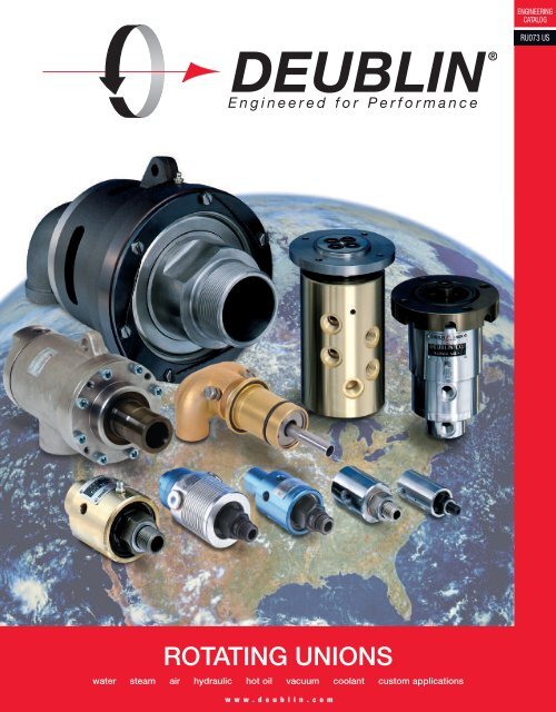
ROTATING UNIONS<br />
water steam air hydraulic hot oil vacuum coolant custom applications<br />
w w w . d e u b l i n . c o m<br />
ENGINEERING<br />
CATALOG<br />
RU073 US
2<br />
Selection Chart for DEUBLIN <strong>Rotating</strong> <strong>Unions</strong><br />
Max. Operating Data<br />
Temp. Speed<br />
Size Series PSI °F RPM Description<br />
Passages Pages<br />
Water & Hot Oil up to 250°F * 6-21<br />
3/8" - 2" 55 750 250 3,500 General Purpose 1 or 2 6 - 10<br />
3/8" - 2" 57 150 200 3,500 Water Service 1 or 2 7 - 10<br />
2 1/2" 755 200 250 750 General Purpose 1 or 2 11<br />
3" 857 150 250 500 Water Service 1 or 2 12 - 13<br />
3/8" - 1" 54 1,800 200 3,500 316 Stainless Steel 1 14<br />
3/8" 927 4,000 200 2,000 Water Service High Pressure 1 15<br />
1/2" - 3/4" 22 1,500 250 250 Water Service Car Wash 1 15<br />
2" - 4" 6000 150 250 750 Water Service Cartridge Seal 1 or 2 16 - 19<br />
5" F127 150 250 750 Water Service 1 or 2 20<br />
3/4" - 1 1/2" 2400 150 250 100 Water Service Continuous Casters 1 or 2 21<br />
Steam & Hot Oil up to 450°F * 22-30<br />
3/8" - 1/2" N Steam 250 400 750 Single Bearing Spherical Seal 1 or 2 22<br />
3/8" - 1/2" N Hot Oil 100 450 750 Single Bearing Spherical Seal 1 or 2 22<br />
3/4" - 2" 9000 Steam 150 365 400 Single Bearing Spherical Seal 1 or 2 23 - 25<br />
3/4" - 2" 9000 Hot Oil 100 450 400 Single Bearing Spherical Seal 1 or 2 23 - 25<br />
1 1/2" HPS Steam 250 400 400 Dual Bearing Spherical Seal 2 26<br />
3/4" - 2" H Steam 150 365 400 Dual Bearing Spherical Seal 1 or 2 27 - 30<br />
2 1/2" - 5" H Steam 150 365 180 Dual Bearing Spherical Seal 1 or 2 27 - 30<br />
3/4" - 2" H Hot Oil 100 450 400 Dual Bearing Spherical Seal 1 or 2 27 - 30<br />
2 1/2" - 5" H Hot Oil 100 450 350 Dual Bearing Spherical Seal 1 or 2 27 - 30<br />
Air & Hydraulic 31-45<br />
1/8" - 3/8" 1005, 1102, 1115 1,000 250 3,500 Standard Applications 1 31 - 32<br />
1/2" 1205, 2200 1,000 250 3,500 Standard Applications 1 31 - 32<br />
3/4" - 1 1/2" 250, 355, 452 1,000 250 3,500 Standard Applications 1 33<br />
1/8" - 3/8" 1005, 1102, 1115 1,000 250 3,500 In-the-shaft Mounted 1 34<br />
1/4" - 1/2" AP 5,700 200 1,500 High Pressure High Speed 1 35<br />
1/4" - 1 1/2" D 6,400 120 20 High Pressure Low Speed or Swivel 1 36<br />
3/8" X 2 1500 150 250 1,500 DEU-PLEX Air 2 37<br />
1/4" X 2 2620 2,000 160 12,000 DEU-PLEX Air & Hyd Oil 2 38 - 39<br />
1/2" X 2 1590 150 250 1,500 DEU-PLEX Air 2 40<br />
1/2" X 2 1579 1,000 250 1,500 DEU-PLEX Hyd Oil 2 40<br />
3/8" - 1/2" X 4 1379, 1479 3,600 175 250 Multi Media 4 Pass 4 41<br />
1/4" - 1/2" 17,21 3,000 250 250 Low Speed Air & Hyd Oil 1 42<br />
1/4" X 1/2" 2117 3,000 250 250 Low Speed Tandem Air & Hyd Oil 2 43<br />
1/4"-1/2"-3/4" X 2 1690, 1790, 1890 3,000 250 250 DEU-PLEX Low Speed 2 44 - 45<br />
1/4" X 3/4" X 3 1890 3,000 250 250 Triple Passage 3 45<br />
Coolant (Wider range of products featured in Coolant Union Catalog) 46-51<br />
3/8" 1117 2,000 160 20,000 Bearingless 1 46<br />
3/8" 1129 2,000 160 20,000 Bearingless ("Pop-Off") High Speed 1 47<br />
3/16" 1101 1,500 160 15,000 Standard Applications High Speed 1 48<br />
3/8" 1116 1,000 160 12,000 Standard Applications 1 49<br />
1/4" - 3/8" 1109 1,500 160 20,000 Dry-run ("Pop-Off") High Speed 1 50<br />
3/8" 902 1,000 160 10,000 Dry-run ("Pop-Off") 1 51<br />
<strong>Unions</strong> for Special Applications * 52-53<br />
1/8" - 1" 1005, 468, 981 750 250 3,500 Water, Oil Rig, Clutch & Brake 1 to 3 52<br />
1/4" - 3/8" 1102, 1115, 882 150 250 3,500 Central Tire Inflation 1 or 2 52<br />
Custom 7000 / 7100 3,000 250 5,000 Around The Shaft 53<br />
* Attention! For applications exceeding indicated limits, contact DEUBLIN. Indicate media, size, speed (RPM), pressure, temperature and connection specifications.<br />
- Subject to technical and dimensional changes without notice.<br />
1 - 8 4 7 -- 6 8 9 - 88 6 0 0 o r w w w . d e u b l i n . c o m
DEUBLIN KEEPS THE WORLD ROTATING<br />
Since 1945, Deublin has grown from a small garage shop to the<br />
world’s largest manufacturer of rotating unions. Today, Deublin’s<br />
international headquarters is located in Waukegan, Illinois, with<br />
manufacturing facilities, sales offices and warehouses located in<br />
17 countries on four continents.<br />
Our worldwide distribution network allows end users all over the<br />
world to specify Deublin unions when purchasing equipment made<br />
in another country. We’re manufacturers ourselves, so we understand<br />
the importance of fast response time to keep your manufacturing<br />
process rolling. Wherever you’re located, Deublin has a stocking<br />
distributor nearby to meet your requirements—quickly.<br />
UNIQUE REQUIREMENTS DEMAND CUSTOM UNIONS<br />
<strong>Rotating</strong> unions must accommodate a broad range of materials,<br />
viscosities, temperatures, pressures and speeds. That’s why the<br />
Deublin product line offers over 500 standard unions, over 3,000<br />
separate models.<br />
Even this extensive line cannot meet all the specialized needs<br />
required by our customers. That’s why we manufacture an evergrowing<br />
line of custom unions to meet individual manufacturers’<br />
particular requirements. In many instances, we can adapt or<br />
convert an existing union and offer a cost-effective solution to<br />
meet your exact specifications.<br />
1 - 8 4 7 - 6 8 9 - 8 6 0 0 o r w w w . d e u b l i n . c o m<br />
DEUBLIN<br />
3
4<br />
A ROTATING UNION FOR EVERY APPLICATION<br />
<strong>Rotating</strong> unions are used in many manufacturing processes to cool,<br />
heat or transfer fluid (pneumatic or hydraulic) power. Typical rotating<br />
unions feature deep groove ball bearings to support the rotating<br />
component against the stationary component, and balanced,<br />
precision-engineered mechanical seals to seal the media flow.<br />
Deublin rotating unions vary for each application, depending on<br />
design, bearing type, construction and material required.<br />
In 1989, the Deublin product line was expanded to include steam<br />
joints and siphon systems for paper machine dryer cans.<br />
Here are just some of the industries that rely on Deublin for their<br />
unique rotating union needs:<br />
• ALUMINUM<br />
• AUTOMOTIVE<br />
• CAN MAKING<br />
• CAR WASH EQUIPMENT<br />
• CHEMICAL/PETROCHEMICAL/REFINERY<br />
• CONSTRUCTION EQUIPMENT<br />
• DISTILLERIES/BREWERIES<br />
• FARM EQUIPMENT<br />
• FLOOR & WALL COVERINGS<br />
• FOOD PROCESSING MACHINERY<br />
• GLASS MANUFACTURING<br />
• INSULATION<br />
• LAUNDRY EQUIPMENT<br />
• LUMBER & WOODWORKING<br />
• MACHINE TOOL<br />
• MARINE<br />
• MINING<br />
• PAPER<br />
- CONVERTING PLANTS<br />
- CORRUGATING<br />
- PULP & PAPERBOARD<br />
- ROOFING<br />
• PETROLEUM<br />
• PLASTICS<br />
• PRINTING<br />
- BUSINESS FORMS<br />
- FLEXOGRAPHIC<br />
- WEB OFFSET<br />
• RUBBER<br />
• STEEL<br />
• TEXTILE<br />
• TIRES<br />
• TRUCKING<br />
DEUBLIN'S state-of-the-art manufacturing facilities are strategically<br />
located worldwide, and feature the latest CNC technologies<br />
including multi-axis/multi-function, robotic interfaces, single point<br />
threading and cylindrical grinding.<br />
These advanced machining techniques and proprietary processes<br />
allow Deublin to achieve the most precise tolerances in the industry,<br />
and ensure superior union performance and service life.<br />
1 - 8 4 7 - 6 8 9 - 8 6 0 0 o r w w w . d e u b l i n . c o m
WE TREAT PRECISION AS AN EXACT SCIENCE<br />
PRECISION<br />
A rotating union must be capable of containing high pressures while<br />
rotating at very high speeds. Smooth, easy rotation can only be<br />
achieved by exactly mating the seal faces to minimize friction.<br />
Precision and tight tolerances are critical in the micro lapping of seal<br />
faces. All Deublin seals are micro lapped to an optical flatness within<br />
2 light bands or 0.000023” utilizing proprietary lapping machinery<br />
and compounds. This level of precision is essential for dependable<br />
leak-proof operation.<br />
Housings are machined on multi-axis twin-spindle lathes to obtain the<br />
necessary part-to-part precision. Rotors and other parts are turned<br />
on automatic bar machines to ensure true-running rotating unions<br />
without any wobble. This assures extended service life.<br />
BALANCED MECHANICAL SEAL<br />
The greater the pressure on a rotating seal face, the greater the<br />
friction, torque and wear on the union. That’s why Deublin rotating<br />
unions feature "balanced mechanical seals." With this technology,<br />
the thrust load or seal face contact pressure is kept to a minimum<br />
regardless of media pressure. This reduces wear, resulting in longer<br />
seal life. The spring-loaded seal is keyed so that it cannot rotate or<br />
creep, which can cause premature failure in secondary seals,<br />
resulting in a leaking union.<br />
Unbalanced Mechanical Seal<br />
Entire line pressure is applied<br />
to seal face.<br />
DEUBLIN Balanced Mechanical Seal<br />
Partial line pressure is applied to seal face.<br />
EXTENDED LIFE SEALING<br />
Responding to ever-increasing speeds and pressures, Deublin<br />
pioneered Extended Life Sealing (E.L.S.). E.L.S. rotating unions offer<br />
outstanding performance under the toughest conditions, and can<br />
extend service life two to four times, depending on the severity of<br />
the application. E.L.S. unions use advanced materials such as<br />
tungsten carbide and silicon carbide to provide the best possible<br />
seal solution for the application.<br />
Where reliability is of prime importance, E.L.S. should be specified<br />
to protect against contaminants and resist wear caused by rust,<br />
scale, chips and other harmful abrasives.<br />
PROFESSIONAL SERVICE AROUND THE WORLD<br />
At Deublin, our service is as reliable as our products. Given the<br />
importance of rotating unions to your equipment’s performance, our<br />
products have to be reliable. To provide you local and emergency<br />
service, we have a worldwide service network consisting of whollyowned<br />
subsidiaries and authorized distribution network.<br />
Whether you need a spare part, a new product, technical advice, or<br />
help with an ongoing design project, our experienced customer<br />
service representatives and engineers are always available to<br />
provide immediate assistance.<br />
For all your rotating union requirements—no matter how unique or<br />
complex—you can rely on Deublin.<br />
NUMBER SYSTEM<br />
DEUBLIN ordering numbers for standard rotating unions consist of<br />
2, 3 or 4 number groups. Each group describes a particular<br />
characteristic feature such as application, seal combination or rotor<br />
connection (refer to ordering example).<br />
Rebuilding and repair kit numbers differ from their respective<br />
rotating union numbers by the insertion of a letter (B or C). The letter<br />
B stands for a rebuilding kit, and the letter C for a repair kit (refer to<br />
ordering example).<br />
ORDERING EXAMPLE:<br />
255-000-284681<br />
rotor<br />
seal combination<br />
model / series / size<br />
255-000B284 257-000C<br />
rebuilding kit<br />
1 - 8 4 7 - 6 8 9 - 8 6 0 0 o r w w w . d e u b l i n . c o m<br />
elbow for<br />
duoflow design<br />
repair kit<br />
DEUBLIN<br />
5
6<br />
Operating Data<br />
Maximum Water Pressure Model 55-555 750 PSI 50 bar<br />
Maximum Water Pressure Model 655 600 PSI 41 bar<br />
Maximum Saturated Steam Pressure (Intermittent) 15 PSI 1 bar<br />
Maximum Hot Oil Pressure 100 PSI 6.6 bar<br />
Maximum Speed NPT Threads Model 55-555 1,500 RPM 1,500/min<br />
Model 655 750 RPM 750/min<br />
Maximum Speed Straight Threads<br />
Model 55-255 3,500 RPM 3,500/min<br />
Model 355 3,000 RPM 3,000/min<br />
Model 525-555 2,500 RPM 2,500/min<br />
Model 655 750 RPM 750/min<br />
Maximum Temperature 250°F >250°F consult DEUBLIN<br />
Torque Ratings 55 Series<br />
Size ft.lbs Nm<br />
55 1 ⁄4 0.34<br />
155 1 ⁄3 0.50<br />
255 1 ⁄2 0.68<br />
355 1 1 ⁄3 1.80<br />
525 1 1 ⁄3 1.80<br />
555 2 1 ⁄2 3.40<br />
655 3 4.07<br />
Illustration shows duoflow with fixed<br />
supply pipe. Monoflow units have<br />
pipe plugs instead of an elbow.<br />
Supply Pipe<br />
(Non-<strong>Rotating</strong> Shown)<br />
Rotor Thread<br />
(See table)<br />
Wrench Flats<br />
Forged Brass<br />
Housing<br />
DEUBLIN<br />
General Purpose<br />
55 Series <strong>Unions</strong><br />
• Monoflow and duoflow design<br />
• Self-supported rotating union<br />
• Radial housing connection<br />
• Balanced mechanical seal<br />
• 3 vent holes<br />
• Forged brass housing<br />
• Stainless steel rotor<br />
• Special options:<br />
threaded vent holes,<br />
low torque design<br />
• Lubrication Guide page 55<br />
Seal Combinations<br />
• Carbon Graphite/Bronze for water - Standard<br />
• Carbon Graphite/Ceramic for hot oil, hot water and<br />
saturated steam - Optional<br />
• Multi-purpose applications<br />
Seal Combination - E.L.S.<br />
• Tungsten Carbide/Ceramic for severe conditions<br />
(poor water quality), max. temperature 200°F<br />
Dual Ball Bearings<br />
Vent<br />
1 - 8 4 7 - 6 8 9 - 8 6 0 0 o r w w w . d e u b l i n . c o m<br />
Stainless<br />
Steel Spring<br />
Duoflow Elbow<br />
(DUO)
Operating Data<br />
Maximum Water Pressure 150 PSI 10 bar<br />
Maximum Speed NPT Threads Model 57-557 1,500 RPM 1,500/min<br />
Model 657 750 RPM 750/min<br />
Maximum Speed Straight Threads<br />
Model 57-257 3,500 RPM 3,500/min<br />
Model 357 3,000 RPM 3,000/min<br />
Model 527-557 2,500 RPM 2,500/min<br />
Model 657 750 RPM 750/min<br />
Maximum Water Temperature 200°F >200°F consult DEUBLIN<br />
Torque Ratings 57 Series<br />
Size ft.lbs Nm<br />
57 1 ⁄4 0.25<br />
157 1 ⁄3 0.50<br />
257 3 ⁄4 1.00<br />
357 1 1 ⁄2 2.00<br />
527 1 1 ⁄2 2.20<br />
557 21 ⁄4 2.90<br />
657 31 ⁄2 4.50<br />
Silicon Carbide Keyed<br />
Rotor Seal<br />
Gasket<br />
Seal Guide<br />
Carbon Graphite/Silicon<br />
Carbide Floating Seal<br />
Coil Spring<br />
Viton-O-Ring<br />
DEUBLIN<br />
57 Series with Silicon Carbide<br />
Seals, for Water Service<br />
• Monoflow and duoflow design<br />
• Self-supported rotating union<br />
• Radial housing connection<br />
• Balanced mechanical seal<br />
• Keyed rotor seal<br />
• Easy and quick replacement of sealing components<br />
(rotor seal, floating seal)<br />
• Ball bearings lubricated for life<br />
• For poor water quality (E.L.S.)<br />
• 3 vent holes<br />
• Forged brass housing<br />
• Stainless steel rotor<br />
• Special options:<br />
threaded vent holes<br />
Seal Combination - Standard<br />
• Carbon Graphite/Silicon Carbide<br />
Seal Combination - E.L.S.<br />
• Silicon Carbide/Silicon Carbide for severe<br />
conditions (poor water quality)<br />
Union Repair<br />
1 - 8 4 7 - 6 8 9 - 8 6 0 0 o r w w w . d e u b l i n . c o m<br />
The 57 Series is designed for quick, easy replacement<br />
of both Floating Seal and the Rotor Seal.<br />
The “57‘s” seal is seated in a keyed counter bore at the<br />
rotor‘s end. The worn seal simply lifts out and the new<br />
one drops right in. Since the entire rotor does not need<br />
to be replaced or relapped, the repair is fast, easy and<br />
on the spot. As you only replace the seals, the repair<br />
cost is very economical.<br />
For Ordering Number of Repair Kit see page 5.<br />
DEUBLIN<br />
7
55 & 57 Series Monoflow Union Specifications<br />
Chart Instructions<br />
Select Union Size and Rotor Thread.<br />
Follow this line to opposite page to<br />
find Duoflow Elbow Specifications.<br />
Add Duoflow Elbow Suffix to the end<br />
of the Ordering Number.<br />
B<br />
Port<br />
NPT<br />
3 ⁄8 "<br />
1 ⁄2 "<br />
3 ⁄4 "<br />
1 "<br />
1 1 ⁄4 "<br />
1 1 ⁄2 "<br />
2 "<br />
† Recessed O-Ring in Rotor End<br />
in Place of Copper Gasket<br />
A<br />
1/16"<br />
D1 Monoflow Length<br />
Across<br />
Flats<br />
J<br />
Lock-up Approx<br />
8 1 - 8 4 7 - 6 8 9 - 8 6 0 0 o r w w w . d e u b l i n . c o m<br />
(3) 11/32" Dia. Vents<br />
Eq. Spaced<br />
A① Ordering Number<br />
55 Series All 55 Series 57 Series 57 Series<br />
C D1D2 E F G H J<br />
Purpose E.L.S. Water Service E.L.S. Rotor Thread<br />
55-000-001 55-147-151 57-000-001 57-050-001 3 ⁄8" NPT RH<br />
13 ⁄4" 315 ⁄16" 413 55-000-002 55-147-152 57-000-002 57-050-002 3 ⁄8" NPT LH<br />
⁄16" 1" 5 ⁄8" 3 ⁄8" 7 ⁄8" 11 2 ⁄16"<br />
55-000-003 55-147-149 57-000-003 57-050-003 5 ⁄8"-18 UNF RH<br />
13 ⁄4" 315 ⁄16" 413 55-000-004 55-147-150 57-000-004 57-050-004 5 ⁄8"-18 UNF LH<br />
⁄16" 1" 5 ⁄8" 3 ⁄8" 7 ⁄8" 1 2⁄2" 55-000-094 55-147-192 57-000-094 57-050-094 G3 55-000-095 55-147-193 57-000-095 57-050-095<br />
⁄8" (BSP)<br />
G<br />
RH<br />
44.5 102 123 26 16 9.5 22 63<br />
3 ⁄8" (BSP) LH<br />
155-000-001 155-208-113 157-000-001 157-050-001 1 ⁄2" NPT RH<br />
21 ⁄4" 413 ⁄16" 57 ⁄8" 17 155-000-002 155-208-114 157-000-002 157-050-002 1 ⁄2" NPT LH<br />
⁄16"<br />
7 ⁄8" 1 ⁄2" 1 1 ⁄8" 1 3 ⁄2"<br />
155-000-021 155-208-185 157-000-021 157-050-021 3 ⁄4"-16 UNF RH<br />
21 ⁄4" 411 ⁄16" 53 ⁄4" 15 155-000-022 155-208-229 157-000-022 157-050-022 3 ⁄4"-16 UNF LH<br />
⁄16"<br />
3 ⁄4" 1 ⁄2" 1 1 ⁄8" 1 3 ⁄16"<br />
155-000-151 155-208-252 157-000-151 157-050-151 G1 155-000-152 155-208-253 157-000-152 157-050-152<br />
⁄2" (BSP)<br />
G<br />
RH<br />
57.2 120 148 34 19 12.7 30 78<br />
1 ⁄2" (BSP) LH<br />
255-000-020 255-052-255 257-000-020 257-050-020 3 ⁄4" NPT RH<br />
27 ⁄8" 59 ⁄16" 63 ⁄4" 17 255-000-021 255-052-256 257-000-021 257-050-021 3 ⁄4" NPT LH<br />
⁄16"<br />
7 ⁄8" 11<br />
⁄16"<br />
1 1⁄4" 1 4 ⁄16"<br />
255-000-003 255-052-258 257-000-135† 257-050-135† 1"-14 UNS RH<br />
2 7 ⁄8" 57 ⁄16" 65 ⁄8" 15 255-000-027 255-052-257 257-000-136† 257-050-136† 1"-14 UNS LH<br />
⁄16"<br />
3 ⁄4" 21<br />
⁄32"<br />
1 1⁄4" 11 3 ⁄16"<br />
255-000-284 255-052-445 257-000-284 257-050-284 G3 255-000-285 255-052-446 257-000-285 257-050-285<br />
⁄4" (BSP)<br />
G<br />
RH<br />
73 138 168 34 19 17.5 32 94<br />
3 ⁄4" (BSP) LH<br />
355-000-002 355-064-186 357-000-002 357-050-002 1" NPT RH<br />
31 ⁄4" 613 ⁄16" 85 ⁄16" 115 ⁄16" 11 ⁄8" 1" 11 ⁄2" 411 355-000-003 355-064-187 357-000-003 357-050-003 1" NPT LH<br />
⁄16"<br />
355-000-019 355-064-328 357-000-019 357-050-019 11 ⁄2"-12 UNF RH<br />
31 ⁄4" 613 ⁄16" 85 ⁄16" 115 ⁄16" 11 ⁄8" 1" 11 ⁄2" 41 355-000-074 355-064-329 357-000-074 357-050-074 1<br />
⁄4"<br />
1 ⁄2"-12 UNF LH<br />
355-000-222<br />
355-000-223<br />
355-064-378<br />
355-064-379<br />
357-000-222<br />
357-000-223<br />
357-050-222<br />
357-050-223<br />
G1" (BSP)<br />
G1" (BSP)<br />
RH<br />
LH<br />
83 166 204 42 21.5 22.2 36 108<br />
525-000-001 525-097-043 527-000-001 527-050-001 11 ⁄4" NPT RH<br />
39 ⁄16" 79 ⁄16" 93 ⁄8" 23 ⁄16" 11 ⁄8" 11 ⁄4" 13 ⁄4" 51 525-000-002 525-097-044 527-000-002 527-050-002 1<br />
⁄4"<br />
1 ⁄4" NPT LH<br />
525-000-026 525-097-095 527-000-026 527-050-026 13 ⁄4"-12 UN RH<br />
39 ⁄16" 79 ⁄16" 93 ⁄8" 23 ⁄16" 13 ⁄16" 11 ⁄4" 13 ⁄4" 411 525-000-027 525-097-096 527-000-027 527-050-027 1<br />
⁄16"<br />
3 ⁄4"-12 UN LH<br />
525-000-054 525-097-122 527-000-054 527-050-054 G11 525-000-055 525-097-123 527-000-055 527-050-055<br />
⁄4" (BSP)<br />
G1<br />
RH<br />
90.5 191 234 54 27 30.2 46 119<br />
1 ⁄4" (BSP) LH<br />
555-000-001 555-033-154 557-000-001 557-050-001 11 ⁄2" NPT RH<br />
41 ⁄4" 81 ⁄2" 105 ⁄16" 27 ⁄16" 13 ⁄16" 11 ⁄2" 21 555-000-002 555-033-160 557-000-002 557-050-002 1<br />
⁄8" 6"<br />
1 ⁄2" NPT LH<br />
555-000-395 555-033-399 557-000-395 557-050-395 2"-12 UN RH<br />
41 ⁄4" 87 ⁄8" 1011 ⁄16" 213 ⁄16" 11 ⁄8" 11 ⁄2" 21 ⁄8" 513 555-000-396 555-033-382 557-000-396 557-050-396 2"-12 UN LH<br />
⁄16"<br />
555-000-198 555-033-288 557-000-198 557-050-198 G11 555-000-199 555-033-289 557-000-199 557-050-199<br />
⁄2" (BSP)<br />
G1<br />
RH<br />
108 225 268 71 29 35 55 147<br />
1 ⁄2" (BSP) LH<br />
655-500-116 655-502-116 657-000-116 657-050-116 2" NPT RH<br />
45 ⁄8" 101 ⁄16" 113 ⁄4"<br />
3" 11 ⁄2" 17 ⁄8" 21 655-500-117 655-502-117 657-000-117 657-050-117 2" NPT LH 12<br />
⁄4" 7"<br />
7 ⁄16"<br />
655-500-124<br />
655-500-125<br />
655-502-124<br />
655-502-125<br />
657-000-124<br />
657-000-125<br />
657-050-124<br />
657-050-125<br />
G2" (BSP)<br />
G2" (BSP)<br />
RH<br />
LH<br />
117 246 289 65 28.6 47 60 164<br />
① Metric threads and other thread sizes are available. Contact factory for further information. For 2", 2 1 ⁄2", 3", 4" and 5" capacity unions refer to pages 11-13 and 16-20.
55 & 57 Series Duoflow Union Specifications<br />
Fixed Supply<br />
Pipe Detail<br />
D2 Duoflow Length<br />
For Description See Page 10<br />
Thread<br />
Specification<br />
O<br />
Pipe Supplied<br />
By Customer<br />
Pipe Supplied<br />
By Customer<br />
G<br />
Rotor Hole<br />
1/16"<br />
1 - 8 4 7 - 6 8 9 - 8 6 0 0 o r w w w . d e u b l i n . c o m<br />
A<br />
<strong>Rotating</strong> Supply<br />
Pipe Detail<br />
D2 Duoflow Length<br />
R Pipe Length Into Union<br />
(3) 11/32" Dia. Vents<br />
Eq. Spaced<br />
H Across<br />
Flats<br />
J<br />
Lock-up Approx.<br />
Fixed Supply Pipe Fixed Supply Tube<br />
<strong>Rotating</strong> Supply Pipe<br />
Elbow Thread R Elbow Tube R Elbow Pipe Pipe S R K<br />
Suffix<br />
Suffix OD<br />
Suffix Size Dia.<br />
NPT<br />
S<br />
M N O<br />
NPT<br />
— — — -030 .250" 4 3 ⁄16" — — — — — 1 ⁄4" 11 ⁄16" 1 3 ⁄8" 1 ⁄4" 2#<br />
— — — -030 .250" 4 3 ⁄16" — — — — — 1 ⁄4" 11 ⁄16" 1 3 ⁄8" 1 ⁄4" 2#<br />
-120 M6X1 98.5 — — — — — — — — 1 ⁄4" 18 35 1 ⁄4" 0.9 Kg<br />
-012 1 ⁄8" NPT 4 3 ⁄4" -061 .375" 5 7 ⁄16" — — — — — 3 ⁄8" 11 ⁄16" 1 1 ⁄2" 3 ⁄8" 3#<br />
-012 1 ⁄8" NPT 3 4 ⁄4" -061 .375" 5 5 ⁄16" -061 1 ⁄8"<br />
.371"<br />
13 .370"<br />
⁄16" 5" 3 ⁄8" 11<br />
⁄16"<br />
1 1 ⁄2" 3 ⁄8" 3#<br />
-199 G1 ⁄8" (BSP) 117 — — — -471 — 9.93<br />
9.90<br />
30 127 3 ⁄8" 18 38 3 ⁄8" 1.4 Kg<br />
-043 1 ⁄4" NPT 1 5 ⁄4" -075 .500"<br />
5 13 -044 1 ⁄8" NPT 1 5 ⁄8" -026 .437"<br />
⁄16" — — — — — 1 ⁄2" 1" 3 1 ⁄4" 1 ⁄2" 5#<br />
-043 1 ⁄4" NPT 1 5 ⁄8" -075 .500"<br />
5 13 ⁄16" -075 1 ⁄4"<br />
.496"<br />
11 ⁄4" 511 -044 1 ⁄8" NPT 5" -026 .437" .495"<br />
⁄16"<br />
1 ⁄2" 1" 3 1 ⁄4" 1 ⁄2" 5#<br />
-368 G1 -367<br />
⁄4" (BSP)<br />
G<br />
136.5<br />
— — — -681 —<br />
12.95<br />
31 146.5 1 ⁄2" 26 45 1 ⁄2" 2.3 Kg<br />
1 ⁄8" (BSP) 132.5 12.90<br />
-083 3 ⁄8" NPT 1 7 ⁄16"<br />
-163 .625" 7 1 -084 1 ⁄4" NPT 7"<br />
⁄8" — — — — — 3 ⁄4" 1 1⁄16" 5 2 ⁄16"<br />
1 ⁄2" 8#<br />
-083 3 ⁄8" NPT 1 7 ⁄16"<br />
-163 .625" 7 1 ⁄8" -163 3 ⁄8"<br />
.621"<br />
11 -084 1 ⁄4" NPT 7" .619"<br />
⁄4" 7" 3 ⁄4" 1 1 ⁄16"<br />
5 2 ⁄16"<br />
1 ⁄2" 8#<br />
-255 G3 ⁄8" (BSP) 162 — -— — -347 — 15.95<br />
15.90<br />
31 175 3 ⁄4" 27 59 1 ⁄2" 3.6 Kg<br />
-007 1 ⁄2" NPT 1 8 ⁄8" -104 .750" 1 8 ⁄4" — — — — — 1" 3 1⁄8" 13 2 ⁄16"<br />
3 ⁄4" 10#<br />
-007 1 ⁄2" NPT 1 8 ⁄8" -104 .750" 1 8 ⁄4" -104 1 ⁄2"<br />
.745"<br />
11 ⁄2" 8 3 ⁄16" 1" 13 ⁄8" 2 13 .743"<br />
⁄16"<br />
3 ⁄4" 10#<br />
-079 G1 ⁄2" (BSP) 185.5 — — — -237 — 21.94<br />
21.89<br />
38 201.5 1" 35 72 3 ⁄4" 4.5 Kg<br />
-013 3 ⁄4" NPT 13 8 ⁄16"<br />
-263 1.000" 91 ⁄8" — — — — — 11 ⁄4" 11 ⁄2" 31 -036 1 ⁄2" NPT 3 8 ⁄4"<br />
⁄16"<br />
3 ⁄4" 16#<br />
-013 3 ⁄4" NPT 3 9 ⁄16"<br />
-263 1.000" 9 1 ⁄2" -144 3 ⁄4"<br />
1.000"<br />
13 ⁄4" 95 ⁄16" 11 ⁄4" 11 ⁄2" 31 -036 1 ⁄2" NPT 1 9 ⁄8" .998"<br />
⁄16"<br />
3 ⁄4" 16#<br />
-221 G3 ⁄4" (BSP) 222 — — — -468 — 25.91<br />
44 244 11 25.81<br />
⁄4" 38 78 3 ⁄4" 7.2 Kg<br />
-013 3 ⁄4" NPT 1 10 ⁄4"<br />
-263 1.000" 10 5 ⁄8" — — — — — 11 ⁄4"<br />
11 ⁄2" 3 1 -183 1" NPT 10<br />
⁄16"<br />
3 ⁄4"<br />
17#<br />
3 ⁄8" 13 ⁄4" 31 ⁄2" 1"<br />
-221 G3 ⁄4" (BSP) 243 — — — -468 — 25.91<br />
44 250 11 25.81<br />
⁄4" 38 78 3 ⁄4" 7.7 Kg<br />
Pipe Ø<br />
Shpg.<br />
Wt.<br />
DEUBLIN<br />
9
Deublin water service unions can be adapted<br />
for Duoflow applications where a single media<br />
is circulated through and around the supply<br />
pipe. Duoflow elbows are available in 3 styles<br />
to accept a variety of different supply systems.<br />
The guidelines shown below should be carefully<br />
considered. A poorly designed supply system<br />
can contribute to premature union failure.<br />
Customer Shaft<br />
*Supplied by customer.<br />
Threaded Pipe<br />
The largest threaded supply pipe achieves the maximum<br />
flow rates available for a particular size union. Stresses at<br />
the pipe thread can cause breakage allowing the pipe to<br />
fall into the roll. For this reason pipe lengths longer than 4<br />
union lengths (4 x D1) and rotational speeds above 1000<br />
RPM should be avoided.<br />
Fixed Tube<br />
Thin wall stainless steel tube silver soldered into the<br />
Duoflow elbow produces the strongest, lightest weight<br />
assembly. The thinner wall sections allow greater flow rates<br />
than the threaded pipe. Maximum flow rates are obtained<br />
with the largest tube available for a given size union. Tube<br />
length is usually limited to 6 union lengths (6 x D1). Speeds<br />
to 3500 RPM are possible.<br />
<strong>Rotating</strong> Pipe<br />
<strong>Rotating</strong> Pipe*<br />
Duoflow Supply Pipe Installations<br />
Adapter* Pilot Gasket<br />
Carbon Filled<br />
TFE Bearing*<br />
<strong>Rotating</strong> pipes are fastened internally to rotate with the roll.<br />
The Duoflow elbow helps to support the pipe and restrict<br />
crosstalk between passages. The pipe must be straight<br />
and concentric to the center line to avoid excessive loading<br />
of the union. The union must also have a rotor with a<br />
straight thread (Example 1"-14" UNS) rather than a tapered<br />
pipe thread to assure concentricity. Rotational speeds<br />
above 1000 RPM should be avoided.<br />
Where long pipes or high speeds are required, an adapter<br />
should be used to avoid transmitting stresses from heavy<br />
pipes, cascading water or vibrations to the union. A typical<br />
adapter is illustrated.<br />
Gasket*<br />
10 1 - 8 4 7 - 6 8 9 - 8 6 0 0 o r w w w . d e u b l i n . c o m<br />
Rotor<br />
Union<br />
Outlet<br />
Stationary Tube<br />
Inlet<br />
Elbow
Operating Data<br />
Maximum Water Pressure 200 PSI 14 bar<br />
Maximum Saturated Steam Pressure (Intermittent) 15 PSI 1 bar<br />
Maximum Speed 750 RPM 750/min<br />
Torque at 120 PSI/8.2 bar 4 ft.lbs. 5.4 Nm<br />
Maximum Temperature 250°F >250°F consult DEUBLIN<br />
Carbon Steel Rotor<br />
B<br />
Port<br />
NPT<br />
21 ⁄2 "<br />
2 1 ⁄2 "<br />
2 1 ⁄2 "<br />
Cast Iron Housing<br />
Pipe Supplied<br />
by Customer<br />
G<br />
A<br />
F<br />
E<br />
H<br />
J<br />
DEUBLIN<br />
2 1 ⁄2" Field Repairable<br />
All Purpose <strong>Unions</strong><br />
• Monoflow and duoflow design<br />
• Self-supported rotating union<br />
• Radial housing connection<br />
• Balanced mechanical seal<br />
• Seal combinations:<br />
Carbon Graphite/Ceramic - standard<br />
Tungsten Carbide/Ceramic - E.L.S.<br />
• 3 vent slots<br />
• Cast iron housing - standard<br />
Cast iron housing nickel-plated - optional<br />
• Steel rotor<br />
• Lubrication Guide page 55<br />
D2<br />
D1 C<br />
R<br />
2" NPT<br />
1 - 8 4 7 - 6 8 9 - 8 6 0 0 o r w w w . d e u b l i n . c o m<br />
B<br />
Dual Ball Bearings<br />
N<br />
P<br />
O<br />
Stainless Steel Spring<br />
Supply Pipe<br />
(Stationary Shown)<br />
Ordering Number A<br />
Rotor Thread<br />
C<br />
Dia.<br />
D1 D2 E F G<br />
Rotor<br />
Hole<br />
H<br />
Dia.<br />
J<br />
Lockup<br />
①<br />
All Purpose E.L.S.<br />
755-700-413-117 755-701-413-117 2<br />
N O<br />
NPT<br />
P<br />
NPT<br />
R Shpg.<br />
Wt.<br />
‡<br />
1 755-700-415-117 755-701-415-117<br />
⁄2" NPT RH<br />
2<br />
7" 1 13 ⁄2" 15" 1 3 ⁄4" 7 1⁄8" 3 2 ⁄8" 9 3 ⁄32"<br />
5 8⁄8" 1 4⁄4" 1 1⁄4" 1" 1 12 ⁄8" 44#<br />
1 ⁄2" NPT LH<br />
755-700-330-117 755-701-330-117 G21 755-700-411-117 755-701-411-117<br />
⁄2" (BSP) RH<br />
G2<br />
178 343 381 82.5 38.1 60.3 83.3 207 108 1 1 ⁄4" 1" 308 20 Kg<br />
1 ⁄2" (BSP) LH<br />
755-702-413-139 755-703-413-139 21 ⁄2" NPT RH<br />
7" 1 1 13 ⁄2" 15⁄4" 1 3⁄4" 7 1⁄8" 3 2 ⁄8" 9 3 ⁄32"<br />
5 8⁄8" 3 4⁄8" 1 1⁄2" 1 1 ⁄2"<br />
121 755-702-415-139 755-703-415-139 2<br />
⁄8" 44#<br />
1 ⁄2" NPT LH<br />
① Monoflow unions can be specified by omitting the -117 or -139 suffix. Flange rotor available upon request. Duoflow rotating pipe models available upon<br />
request. For recirculating water service (equal in and out flow) use 1 1 ⁄2" supply pipe.<br />
DEUBLIN<br />
11
12<br />
Operating Data<br />
Maximum Water Pressure 150 PSI 10 bar<br />
Maximum Saturated Steam Pressure (Intermittent) 15 PSI 1 bar<br />
Maximum Speed 500 RPM 500/min<br />
Torque @ 150 PSI/10bar 6 ft.lbs 8.2 Nm<br />
Maximum Water Temperature 250°F >250°F consult DEUBLIN<br />
Carbon Steel Rotor<br />
Dual Ball Bearings<br />
Cast Iron Housing<br />
DEUBLIN<br />
3" Union for Rubber<br />
and Plastic Application<br />
• Monoflow and duoflow design<br />
• Self-supported rotating union<br />
• Radial housing connection<br />
• Balanced mechanical seal<br />
• Seal combination:<br />
Carbon Graphite/Tungsten Carbide<br />
• Full-media flow<br />
• Easy and quick replacement of sealing components<br />
(rotor seal, floating seal)<br />
• Vented housing<br />
• Cast iron housing - standard<br />
• Steel rotor<br />
• Lubrication Guide page 55<br />
Vent<br />
1 - 8 4 7 - 6 8 9 - 8 6 0 0 o r w w w . d e u b l i n . c o m<br />
Supply Pipe<br />
(<strong>Rotating</strong> Shown)<br />
Composite Bearing
857 Series Specifications<br />
7/8"<br />
31 D<br />
R<br />
J<br />
/2"<br />
2<br />
9" Dia. G<br />
7/8"<br />
4.004"<br />
4.002" Dia.<br />
Pilot Dia.<br />
(6) 11/16" Dia. Bolt Holes<br />
on a 7 9/16" DBC<br />
Pipe Supplied<br />
By Customer<br />
G<br />
B<br />
Port NPT<br />
Type I<br />
Type II<br />
Type III<br />
3 "<br />
2 "<br />
2 "<br />
Flange O-Ring<br />
size 2-353<br />
A<br />
F<br />
E<br />
1/4"<br />
857-132 Flanged Rotor Detail<br />
D<br />
R<br />
Pipe Length Into Union<br />
C<br />
H (Across Flats) B<br />
J<br />
Type I Type II Type III<br />
1313/16" 1715/16" 1715/16"<br />
14" 14 5/16"<br />
1011/16"<br />
913/16"<br />
913/16"<br />
A<br />
3" NPT<br />
Type II<br />
Duoflow Fixed Pipe<br />
E<br />
F<br />
P<br />
N<br />
C<br />
D<br />
H (Across Flats)<br />
J<br />
O<br />
Type I<br />
Monoflow<br />
B<br />
1/16"<br />
3.430" 27/8"<br />
3.425" Dia.<br />
Dia.<br />
11/4"<br />
Type I Type II Type III<br />
D 1411/16" 1813/16" 1813/16"<br />
R<br />
14 7/8" 153/16"<br />
J 1011/16"<br />
913/16"<br />
913/16"<br />
43/8"<br />
7/8"<br />
3.312"<br />
3.307"<br />
Dia.<br />
857-128 Quick Connect<br />
Rotor Detail<br />
R<br />
Pipe Length Into Union<br />
S<br />
T-Dia.<br />
Type III<br />
Duoflow <strong>Rotating</strong> Pipe<br />
857-000-101 3" NPT RH<br />
71 ⁄2" 133 ⁄4" 37 ⁄16" 17 ⁄8" 27 ⁄8" 4" 109 857-000-102 3" NPT LH<br />
⁄16" - - - - - - 50#<br />
857-000-118<br />
857-000-119<br />
G3" (BSP) RH<br />
G3" (BSP) LH<br />
190 344 83 44 73 102 244 - - - - - - 23 Kg<br />
857-001-101 3" NPT RH<br />
71 ⁄2" 177 ⁄8" 37 ⁄16" 17 ⁄8" 27 ⁄8" 4" 93 ⁄4" 511 ⁄16" 2" 2" 1315 857-001-102 3" NPT LH<br />
⁄16" - - 55#<br />
857-001-118<br />
857-001-119<br />
G3" (BSP) RH<br />
G3" (BSP) LH<br />
190 451 83 44 73 102 228 144 2" 2" 351 - - 25 Kg<br />
857-002-101 3" NPT RH<br />
71 ⁄2" 177 ⁄8" 37 ⁄16" 17 ⁄8" 27 ⁄8" 4" 93 ⁄4" 511 ⁄16" 2" - 141 ⁄4" 23 ⁄4" 2.308"<br />
Ordering<br />
A<br />
C D E F G H J N O P R S T Shpg.<br />
Number Rotor Thread Dia.<br />
NPT NPT<br />
Wt.<br />
857-002-102 3" NPT LH 2.302"<br />
55#<br />
857-002-118<br />
857-002-119<br />
G3" (BSP) RH<br />
G3" (BSP) LH<br />
190 451 83 44 73 102 228 144 2" - 355 70<br />
58.62<br />
58.47<br />
25 Kg<br />
DEUBLIN<br />
1 - 8 4 7 - 6 8 9 - 8 6 0 0 o r w w w . d e u b l i n . c o m<br />
13
Operating Data<br />
Maximum Pressure and Maximum Speed See Diagram<br />
Maximum Speed NPT 1,500 RPM 1,500/min<br />
B<br />
Port<br />
NPT<br />
3 ⁄8 "<br />
1 ⁄2 "<br />
3 ⁄4 "<br />
1 "<br />
Maximum Temperature 200°F >200°F consult DEUBLIN<br />
(Temperatures above 160°F pressure should not exceed 150 PSI (10 bar)<br />
and media must be in liquid form.)<br />
T<br />
1 /16"<br />
Ordering Number<br />
Standard Model E.L.S. Model<br />
Note: 1 1 ⁄4" & 1 1 ⁄2" available<br />
14<br />
G<br />
A<br />
F<br />
E<br />
A<br />
Rotor Thread<br />
C<br />
D<br />
H Across Flats<br />
C<br />
Dia.<br />
J<br />
DEUBLIN<br />
Stainless Steel <strong>Unions</strong><br />
• Monoflow and duoflow (available) design<br />
• Self-supported rotating union<br />
• Radial or axial (available) housing connection<br />
• Seal combinations:<br />
Carbon Graphite/Ceramic - standard<br />
Tungsten Carbide/Ceramic - E.L.S.<br />
• Wetted parts made of 316 stainless steel<br />
• Suitable for the food, chemical & pharmaceutical industries<br />
• Full-media flow<br />
54-050-117 54-051-112 3 ⁄8" NPT RH 1 15 ⁄16" 4" 1 1 ⁄16" 5 ⁄8" 3 ⁄8" 3 ⁄4" 3" 7 ⁄8" 1 1 ⁄2#<br />
54-050-178 54-051-110 G 3 ⁄8" (BSP) RH 49 101 26 16 9.5 19 71.5 22 1.1 Kg<br />
154-050-117 154-051-112 1 ⁄2" NPT RH 2 1 ⁄2" 4 15 ⁄16" 1 7 ⁄16" 7 ⁄8" 1 ⁄2" 15 ⁄16" 3 3 ⁄4" 1 3 ⁄16" 2#<br />
154-050-178 154-051-110 G 1 ⁄2" (BSP) RH 64 123 34 19 12.7 24 89 30 1.8 Kg<br />
254-050-117 254-051-112 3 ⁄4" NPT RH 2 7 ⁄8" 5 7 ⁄16" 1 15 ⁄32" 7 ⁄8" 11 ⁄16" 1 3 ⁄16" 4 1 ⁄16" 1 3 ⁄8" 5 3 ⁄4#<br />
254-050-178 254-051-110 G 3 ⁄4" (BSP) RH 73 135 34 19 17.5 30 98 35 2.6 Kg<br />
354-050-117 354-051-112 1" NPT RH 3 11 ⁄16" 6 9 ⁄16" 1 15 ⁄16" 1 1 ⁄8" 7 ⁄8" 1 7 ⁄16" 4 7 ⁄8" 1 25 ⁄32" 11 1 ⁄4#<br />
354-050-178 354-051-110 G1" (BSP) RH 94 161 43 22 22.2 36 117 45 5.1 Kg<br />
1 - 8 4 7 - 6 8 9 - 8 6 0 0 o r w w w . d e u b l i n . c o m<br />
Pressure<br />
1800<br />
1500<br />
1200<br />
900<br />
600<br />
300<br />
PSI<br />
RPM<br />
(3) Vent Hole 11 /32" Dia.<br />
B<br />
Speed<br />
D E F G H<br />
J T Shpg.<br />
Wt.
B<br />
Port<br />
NPT<br />
3 "<br />
⁄8<br />
3 "<br />
⁄8<br />
927-150-151 3 ⁄4"-16 UNF RH<br />
927-150-152 3 ⁄4"-16 UNF LH<br />
Operating Data<br />
Maximum Water Pressure ① 1,500 PSI 105 bar<br />
Maximum Speed ① 250 RPM 250/min<br />
Maximum Temperature 250°F 121°C<br />
① Union is designed for continuous operation at either maximum speed or<br />
maximum pressure. If operating conditions are close to maximum pressure<br />
and speed simultaneously, consult DEUBLIN.<br />
(Not suitable for overhead boom.)<br />
B<br />
Port NPT<br />
Operating Data<br />
Maximum Water Pressure 4,000 PSI 276 bar<br />
Maximum Speed 2,000 RPM 2,000/min<br />
Maximum Flow 4 GPM 15 L/min<br />
Maximum Temperature 200°F 90°C<br />
Ordering<br />
Number<br />
A<br />
Rotor Thread<br />
Ordering Number A<br />
Rotor Thread<br />
3 ⁄4" 22-001-101 1 ⁄2" NPT RH<br />
3 ⁄4" 22-001-102 1 ⁄2" NPT LH<br />
3 ⁄4" 22-001-103 3 ⁄4" NPT RH<br />
3 ⁄4" 22-001-104 3 ⁄4" NPT LH<br />
2 1 ⁄4" 5 5 ⁄8" 1 9 ⁄16" 3 ⁄4" 3 ⁄16" 1 1 ⁄8" 1" 1 1 ⁄4" 3#<br />
2 3 ⁄4" 5 9 ⁄16" 1 7 ⁄8"<br />
2 3 ⁄4" 5 3 ⁄4" 2 1 ⁄16"<br />
DEUBLIN<br />
Model 927 High Pressure /<br />
Low Torque Water Union<br />
• Monoflow design<br />
• Self-supported rotating union<br />
• Axial housing connection<br />
• Balanced mechanical seal<br />
• Seal combination:<br />
Tungsten Carbide/Tungsten Carbide<br />
• Slinger and vents protect bearings<br />
• Low torque design<br />
• Stainless steel housing and rotor<br />
1/16"<br />
C D E F<br />
G<br />
Rotor<br />
Hole<br />
DEUBLIN<br />
Model 22 Car Wash Union<br />
• Monoflow design<br />
• Self-supported rotating union<br />
• Radial housing connection<br />
• Seal combination:<br />
Silicon Carbide/Silicon Carbide<br />
• Stainless steel housing and rotor<br />
C D E F G<br />
H<br />
J Shpg.<br />
Rotor Hole Across Flats Approx.<br />
Lock-up Wt.<br />
1 - 8 4 7 - 6 8 9 - 8 6 0 0 o r w w w . d e u b l i n . c o m<br />
G<br />
A<br />
G<br />
A<br />
F<br />
11 ⁄16"<br />
7 ⁄8"<br />
F<br />
E<br />
E<br />
H<br />
H<br />
H<br />
Across<br />
Flats<br />
J<br />
C<br />
C<br />
D<br />
D<br />
K<br />
L<br />
Across<br />
Flats<br />
1 ⁄2" 1 1 ⁄8" 2 11 ⁄16" 4 3 ⁄4#<br />
1 ⁄2" 1 1 ⁄8" 2 7 ⁄8" 4 3 ⁄4#<br />
B<br />
K<br />
B<br />
L<br />
Shpg.<br />
Wt.<br />
DEUBLIN<br />
15
Operating Data<br />
Maximum Water Pressure 150 PSI 10 bar<br />
Maximum Speed 750 RPM 750/min<br />
Torque for Model 6200 4 ft.lbs 5.4 Nm<br />
Model 6250 7 ft.lbs 9.5 Nm<br />
Model 6300 8 ft.lbs 10.9 Nm<br />
Model 6400 10 ft.lbs 13.6 Nm<br />
Maximum Temperature 250°F >250°F consult DEUBLIN<br />
Carbon Steel Rotor<br />
Cast Iron Housing<br />
Heavy-Duty<br />
Dual Ball Bearings<br />
Replaceable Rotor Seal<br />
Torque Lug<br />
Vent<br />
Replaceable<br />
Seal Cartridge<br />
DEUBLIN<br />
2", 2 1 ⁄2", 3"&4" Cartridge<br />
Water <strong>Unions</strong><br />
• Monoflow and duoflow design<br />
• Self-supported rotating union<br />
• Radial housing connection<br />
• Balanced mechanical seal<br />
• Seal combinations:<br />
Carbon Graphite/Tungsten Carbide - standard<br />
Silicon Carbide/Tungsten Carbide - E.L.S.<br />
• Steel-banded floating seal<br />
• Easy and quick replacement of sealing components<br />
• Full-media flow<br />
• Vent slots<br />
• Cast iron housing<br />
• Steel rotor flanged/threaded<br />
• Lubrication Guide page 55<br />
Cast Iron End Cap<br />
(nickel-plated)<br />
Composite Bearing<br />
DEUBLIN Exclusive<br />
On-The-Machine<br />
Repair Cartridge<br />
Seals are replaced quickly and easily. There‘s<br />
no need to remove hose connections or use<br />
special tools. Make sure the system is cold and<br />
pressureless! Simply remove 6 hex bolts and<br />
end cap, then remove floating seal cartridge<br />
and rotor seal face and replace with new seals.<br />
Rotor seal is keyed and sealed to the rotor<br />
with a built-in O-Ring. Replace end cap, hex<br />
bolts and safety wire. Detailed instructions<br />
available from DEUBLIN.<br />
16 1 - 8 4 7 - 6 8 9 - 8 6 0 0 o r w w w . d e u b l i n . c o m<br />
Supply Pipe<br />
(<strong>Rotating</strong> Shown)
B<br />
Port<br />
NPT<br />
Monoflow <strong>Rotating</strong> Union<br />
Threaded Rotor<br />
Flanged Rotor<br />
Flanged O-Ring<br />
(supplied by DEUBLIN) for:<br />
Model O-Ring Size<br />
6200 2-343 Viton<br />
6250 2-343 Viton<br />
6300 2-353 Viton<br />
6400 2-361 Viton<br />
Ordering Number<br />
Standard E.L.S.<br />
A<br />
Dia. W<br />
B.C. Pilot<br />
Dia.<br />
A<br />
Rotor Thread<br />
J<br />
Lock-up<br />
J<br />
Lock-up<br />
R Dia.<br />
Lug Hole<br />
C D1 E F G J L M Q R T U W Pilot X Y Z<br />
Dia.<br />
NPT<br />
21 ⁄2 "<br />
2 "<br />
3 "<br />
4 "<br />
6200-001-123 6200-016-123 2" NPT<br />
6200-001-135 6200-016-135 2" NPT<br />
RH 1 5 ⁄4"<br />
LH<br />
15 1 7 5 7 9 1 12" 2 ⁄16" 1⁄2" 1⁄8" 9 ⁄8" 2 ⁄8" 3 ⁄16" 3⁄16" 1 ⁄2" – – – – – – 2" 21#<br />
6200-001-137 6200-016-137 G2"(BSP) RH<br />
133<br />
6200-001-139 6200-016-139 G2"(BSP) LH<br />
295 63.5 28.6 47 228 73 90 78 12.7 – – – – – – 2" 9.5 Kg<br />
9" O.D.<br />
6200-001-115 6200-016-115 5<br />
Note: Threaded Rotors Not For Calender Service.<br />
1 ⁄4" 12" 31 ⁄4" 1" 17 ⁄8" 101 ⁄4" 27 ⁄8" 39 ⁄16" 31 FLANGE<br />
⁄16"<br />
1 ⁄2" 4<br />
8.317" 11 3<br />
⁄16" 6 ⁄8"<br />
8.315"<br />
– 1 ⁄4" 2" 32#<br />
6250-001-115 6250-018-115 21 ⁄2"NPT RH<br />
6250-001-119 6250-018-119 2<br />
7" 5 1 7 3 14 ⁄8" 3⁄4" 1 ⁄8" 2 ⁄8" 3 7 7 12" 3 ⁄4" 4 ⁄16" 3 ⁄8" 9<br />
⁄16" – – – – – – 1 2⁄2" 1 44⁄2# 1 ⁄2"NPT LH<br />
6250-001-121 6250-018-121 G21 ⁄2"(BSP)RH<br />
178<br />
6250-001-123 6250-018-123 G2<br />
371 82.5 38.1 60 290 95 113 98 14.3 – – – – – – 1 2 ⁄2" 20.2 Kg<br />
1 ⁄2"(BSP)LH<br />
9" O.D.<br />
6250-001-300 6250-018-300 7" 15" 35 ⁄8" 1" 23 ⁄8" 1215 ⁄16"33 ⁄4" 47 ⁄16" 37 FLANGE<br />
⁄8" 9<br />
⁄16" 4<br />
8.317" 11 3<br />
⁄16" 6 ⁄8"<br />
8.315"<br />
– 1 ⁄4" 1 2⁄2" 59#<br />
6300-001-157 6300-015-157 3" NPT<br />
6300-001-158 6300-015-158 3" NPT<br />
RH<br />
LH<br />
3 7 7 7 9" 17 ⁄16" 3 ⁄8" 1 ⁄8" 2 ⁄8" 7 5 3 14" 3 ⁄16" 5 ⁄16" 4 ⁄4" 9<br />
⁄16" – – – – – – 3" 98#<br />
6300-001-161 6300-015-161 G3"(BSP) RH<br />
229<br />
6300-001-162 6300-015-162 G3"(BSP) LH<br />
433 95 44.4 73 335 87 135 121 14.3 – – – – – – 3" 45.5 Kg<br />
9" O.D.<br />
6300-001-103 6300-015-103 9" 163 ⁄4" 37 ⁄16" 7 ⁄8" 3" 141 ⁄2" 37 ⁄16" 55 ⁄16" 43 ⁄4" 9 FLANGE<br />
⁄16" 6<br />
4.004" 11 9<br />
⁄16" 7 ⁄16"<br />
4.002"<br />
1⁄4" – 3" 113#<br />
6400-030-330 6400-042-330 107 ⁄8" O.D.<br />
FLANGE<br />
11" 19" 3" 7 ⁄8" 4" 3 3 1 1 16 ⁄8" 3 ⁄4" 6 ⁄8" 5 ⁄4" 5 ⁄8" 6 13<br />
⁄16" 9"<br />
4.749"<br />
.300<br />
4.746"<br />
– 4" 156#<br />
1 - 8 4 7 - 6 8 9 - 8 6 0 0 o r w w w . d e u b l i n . c o m<br />
Z<br />
Shpg.<br />
Wt.<br />
DEUBLIN<br />
17
Flanged/Threaded Duoflow <strong>Rotating</strong> Pipe<br />
B & O<br />
Port NPT<br />
(2) x 1 "<br />
(2) x 1 1 ⁄2 "<br />
(2) x 2 "<br />
(2) x 2 1 ⁄2 "<br />
A<br />
F<br />
E<br />
J<br />
Lock-up<br />
Supplied By<br />
Customer<br />
A<br />
Dia. W<br />
B.C. Pilot<br />
Dia. G<br />
RP<br />
E L<br />
F<br />
X T / U<br />
18 1 - 8 4 7 - 6 8 9 - 8 6 0 0 o r w w w . d e u b l i n . c o m<br />
Y<br />
C<br />
K<br />
Pipe Length Into Union<br />
J<br />
Lock-up<br />
D2<br />
R Dia.<br />
Lug Hole<br />
Q<br />
M<br />
S<br />
Pipe Dia.<br />
N<br />
Approx.<br />
B & O<br />
Port NPT<br />
Standard E.L.S. A C D2E F G J K L<br />
(2) x 1 "<br />
(2) x 2 "<br />
(2) x 11 ⁄2 "<br />
(2) x 21 ⁄2 "<br />
Duoflow <strong>Rotating</strong> Pipe Models<br />
6200-002-123 6200-030-123 2" NPT RH<br />
5<br />
Duoflow Fixed Pipe Models<br />
1 ⁄4" 127 ⁄8" 215 ⁄16" 11 ⁄2" 17 ⁄8" 8" 105 ⁄8" 27 6200-002-135 6200-030-135 2" NPT LH<br />
⁄8"<br />
6200-002-137<br />
6200-002-139<br />
6200-030-137<br />
6200-030-139<br />
G2" (BSP)<br />
G2" (BSP)<br />
RH<br />
LH<br />
133 314 63.5 28.6 47 189 260 73<br />
6200-002-115 6200-030-115<br />
9" O.D.<br />
51 ⁄4" 133 ⁄16" 31 ⁄4" 1" 17 ⁄8" 85 ⁄8" 1015 ⁄16" 27 FLANGE<br />
⁄8"<br />
6250-002-115 6250-030-115 21 ⁄2" NPT RH<br />
7" 157 ⁄8" 31 ⁄4" 17 ⁄8" 23 ⁄8" 93 ⁄4" 1213 ⁄16" 33 6250-002-119 6250-030-119 2<br />
⁄4"<br />
1 ⁄2" NPT LH<br />
6250-002-121 6250-030-121 G21 6250-002-123 6250-030-123<br />
⁄2" (BSP)<br />
G2<br />
RH<br />
178 403 82.5 38.1 60 228.6 325 95<br />
1 ⁄2" (BSP) LH<br />
6250-002-300 6250-030-300<br />
9" O.D.<br />
7" 161 ⁄4" 35 ⁄8" 1" 23 ⁄8" 109 ⁄16" 131 ⁄2" 33 FLANGE<br />
⁄4"<br />
6300-002-157 6300-030-157 3" NPT RH<br />
9" 20" 37 ⁄8" 17 ⁄8" 27 ⁄8" 121 ⁄4" 163 ⁄8" 37 6300-002-158 6300-030-158 3" NPT LH<br />
⁄16"<br />
6300-002-161<br />
6300-002-162<br />
6300-030-161<br />
6300-030-162<br />
G3" (BSP)<br />
G3" (BSP)<br />
RH<br />
LH<br />
229 505 95 44.4 73 288.9 412 87<br />
6300-002-103 6300-030-103<br />
9" O.D.<br />
9" 199 ⁄16" 37 FLANGE<br />
⁄16"<br />
7 ⁄8" 3" 3 12 ⁄4" 16" 7 3 ⁄16"<br />
6400-031-330 6400-051-330<br />
107 ⁄8" O.D.<br />
11" 213 FLANGE<br />
⁄8" 3" 7 ⁄8" 4" 3 13 ⁄4" 1 17 ⁄2" 3 3 ⁄4"<br />
Standard E.L.S. A C D2E F G J K L<br />
6200-011-123 6200-040-123 2" NPT RH<br />
6200-011-135 6200-040-135 2" NPT LH<br />
6200-013-137 6200-020-137 G2" (BSP) RH<br />
6200-013-139 6200-020-139 G2" (BSP) LH<br />
6200-011-115 6200-040-115<br />
9" O.D.<br />
FLANGE<br />
6250-006-115 6250-040-115 21 ⁄2" NPT RH<br />
6250-006-119 6250-040-119 21 ⁄2" NPT LH<br />
6250-025-121 6250-035-121 G21 ⁄2" (BSP) RH<br />
6250-025-123 6250-035-123 G21 ⁄2" (BSP) LH<br />
6250-006-300 6250-040-300<br />
9" O.D.<br />
FLANGE<br />
6300-006-157 6300-040-157 3" NPT RH<br />
6300-006-158 6300-040-158 3" NPT LH<br />
6300-025-161 6300-035-161 G3" (BSP) RH<br />
6300-025-162 6300-035-162 G3" (BSP) LH<br />
6300-006-103 6300-040-103<br />
9" O.D.<br />
FLANGE<br />
6400-024-330 6400-054-330<br />
107 ⁄8" O.D.<br />
FLANGE<br />
5 1 ⁄4" 12 7 ⁄8" 2 15 ⁄16" 1 1 ⁄2" 1 7 ⁄8" 8" 10 1 ⁄8" 2 7 ⁄8"<br />
133 314 63.5 28.6 47 189 246 73<br />
5 1 ⁄4" 13 3 ⁄16" 3 1 ⁄4" 1" 1 7 ⁄8" 8 5 ⁄8" 10 1 ⁄16" 2 7 ⁄8"<br />
7" 15 7 ⁄8" 3 1 ⁄4" 1 7 ⁄8" 2 3 ⁄8" 9 3 ⁄4" 13" 3 3 ⁄4"<br />
178 403 82.5 38.1 60 228.6 330 95<br />
7" 16 1 ⁄4" 3 5 ⁄8" 1" 2 3 ⁄8" 10 9 ⁄16" 13 3 ⁄8" 3 3 ⁄4"<br />
9" 20" 3 7 ⁄8" 1 7 ⁄8" 2 7 ⁄8" 12 1 ⁄4" 16 1 ⁄16" 3 7 ⁄16"<br />
229 505 95 44.4 73 288.9 404 87<br />
9" 19 9 ⁄16" 3 7 ⁄16" 7 ⁄8" 3" 12 3 ⁄4" 16 3 7 ⁄16"<br />
11" 21 3 ⁄8" 3" 7 ⁄8" 4" 13 3 ⁄4" 17" 3 3 ⁄4"<br />
Z
Flanged/Threaded Duoflow Fixed Pipe<br />
A<br />
F<br />
E<br />
M N O<br />
NPT<br />
3 9 ⁄16" 3 3 ⁄8" 1"<br />
90 86 1"<br />
3 9 ⁄16" 3 3 ⁄8" 1"<br />
4 7 ⁄16" 4 1 ⁄16" 1 1 ⁄2"<br />
113 103 1 1 ⁄2"<br />
4 7 ⁄16" 4 1 ⁄16" 1 1 ⁄2"<br />
5 5 ⁄16" 5 3 ⁄16" 2"<br />
135 132 2"<br />
5 5 ⁄16" 5 3 ⁄16" 2"<br />
6 1 ⁄8" 5 3 ⁄4" 2 1 ⁄2"<br />
M N O<br />
NPT<br />
3 9 ⁄16" 3 3 ⁄8" 1"<br />
90 86 1"<br />
3 9 ⁄16" 3 3 ⁄8" 1"<br />
4 7 ⁄16" 4 1 ⁄16" 1 1 ⁄2"<br />
113 103 1 1 ⁄2"<br />
4 7 ⁄16" 4 1 ⁄16" 1 1 ⁄2"<br />
5 5 ⁄16" 5 3 ⁄16" 2"<br />
135 132 2"<br />
5 5 ⁄16" 5 3 ⁄16" 2"<br />
6 1 ⁄8" 5 3 ⁄4" 2 1 ⁄2"<br />
Pipe<br />
Dia.<br />
1.245"<br />
1.240"<br />
31.62<br />
31.49<br />
1.245"<br />
J<br />
Lock-up<br />
A<br />
Dia.<br />
W<br />
B.C.<br />
Supplied By<br />
Customer<br />
Pilot<br />
Dia.<br />
RP Q R S<br />
1" 3 1 ⁄16"<br />
X<br />
Y<br />
K Pipe Length Into Union<br />
J<br />
Lock-up<br />
1 - 8 4 7 - 6 8 9 - 8 6 0 0 o r w w w . d e u b l i n . c o m<br />
F<br />
E<br />
L<br />
T / U<br />
D2<br />
R Dia. Lug Hole<br />
Q<br />
T U W Pilot<br />
Dia.<br />
FP Q R T U W Pilot<br />
Dia.<br />
B<br />
M<br />
FP<br />
N<br />
Approx.<br />
Z<br />
O<br />
X Y Z<br />
NPT<br />
X Y Z<br />
NPT<br />
Shpg.<br />
Wt.<br />
1 ⁄2" 1 1 ⁄2" – – – – – – 2" 29#<br />
1" 78 12.7 38 – – – – – – 2" 13.2 Kg<br />
1" 3 1 1.240"<br />
⁄16"<br />
1<br />
⁄2"<br />
1<br />
1 ⁄2" 4<br />
11<br />
⁄16"<br />
3<br />
6 ⁄8"<br />
8.317"<br />
8.315"<br />
–<br />
1<br />
⁄4" 2" 40#<br />
1.867"<br />
1 1 ⁄2" 3 7 1.865"<br />
⁄8"<br />
9<br />
⁄16"<br />
5<br />
1 ⁄8" – – – – – –<br />
1<br />
2 ⁄2"<br />
1<br />
55 ⁄2#<br />
47.42<br />
1 1 ⁄2" 98 14.3 41 – – – – – – 2 1 47.37<br />
⁄2" 25.2 Kg<br />
1.867"<br />
1 1 ⁄2" 3 7 1.865"<br />
⁄8"<br />
9<br />
⁄16"<br />
5<br />
1 ⁄8" 4<br />
11<br />
⁄16"<br />
3<br />
6 ⁄8"<br />
8.317"<br />
8.315"<br />
–<br />
1<br />
⁄4"<br />
1<br />
2 ⁄2" 70#<br />
2.308"<br />
2" 4 3 2.302"<br />
⁄4"<br />
9<br />
⁄16"<br />
3<br />
2 ⁄4" – – – – – – 3" 105#<br />
58.62<br />
58.47<br />
2" 121 14.3 70 – – – – – – 3" 47.7 Kg<br />
2.308"<br />
2" 4 3 2.302"<br />
⁄4"<br />
9<br />
⁄16"<br />
3<br />
2 ⁄4" 6<br />
11<br />
⁄16"<br />
9<br />
7 ⁄16"<br />
4.004"<br />
4.002"<br />
1<br />
⁄4" – 3" 120#<br />
2.745"<br />
2 1 ⁄2" 5 1 2.742"<br />
⁄4"<br />
5<br />
⁄8"<br />
1<br />
2 ⁄2" 6<br />
13<br />
⁄16" 9"<br />
4.749"<br />
4.746"<br />
.300" – 4" 168#<br />
1"<br />
3 1 NPT<br />
⁄16"<br />
1<br />
⁄2" – – – - – – 2" 29#<br />
G1"<br />
(BSP)<br />
78 12.7 – – – – – – 2" 13.2 Kg<br />
1"<br />
3 1 NPT<br />
⁄16"<br />
1<br />
⁄2" 4<br />
11<br />
⁄16"<br />
3<br />
6 ⁄8"<br />
8.317"<br />
8.315"<br />
–<br />
1<br />
⁄4" 2" 40#<br />
11 ⁄2"<br />
3 7 NPT<br />
⁄8"<br />
9<br />
⁄16" – – – – – –<br />
1<br />
2 ⁄2"<br />
1<br />
55 ⁄2#<br />
G11 ⁄2"<br />
98 14.3 – – – – – – 2 1 (BSP)<br />
⁄2" 25.2 Kg<br />
11 ⁄2"<br />
3 7 NPT<br />
⁄8"<br />
9<br />
⁄16" 4<br />
11<br />
⁄16"<br />
3<br />
6 ⁄8"<br />
8.317"<br />
8.315"<br />
–<br />
1<br />
⁄4"<br />
1<br />
2 ⁄2" 70#<br />
2"<br />
4 3 NPT<br />
⁄4"<br />
9<br />
⁄16" – – – – – – 3" 105#<br />
G2"<br />
(BSP)<br />
121 14.3 – – – – – – 3" 47.7 Kg<br />
2"<br />
4 3 NPT<br />
⁄4"<br />
9<br />
⁄16" 6<br />
11<br />
⁄16"<br />
9<br />
7 ⁄16"<br />
4.004"<br />
4.002"<br />
1<br />
⁄4" – 3" 120#<br />
21 ⁄2"<br />
5 1 NPT<br />
⁄4"<br />
5<br />
⁄8" 6<br />
13<br />
⁄16" 9"<br />
4.749"<br />
4.746"<br />
.300" – 4" 168#<br />
Shpg.<br />
Wt.<br />
DEUBLIN<br />
19
Operating Data<br />
Maximum Water Pressure① 230 PSI 16 bar<br />
Maximum Speed ① 1,000 RPM 1,000/min<br />
Maximum Temperature 250°F >250°F consult DEUBLIN<br />
① Union is designed for continuous operation at either maximum speed or<br />
maximum pressure. If operating conditions are close to maximum pressure<br />
and speed simultaneously, consult DEUBLIN.<br />
A<br />
Dia.<br />
W<br />
B.C.<br />
Monoflow Union<br />
B<br />
Port<br />
5 "<br />
ANSI<br />
B<br />
Port<br />
(2) 3 "<br />
ANSI<br />
Pilot<br />
Dia.<br />
X<br />
G<br />
F<br />
E<br />
L<br />
T / U<br />
J<br />
Lock-up<br />
Duoflow <strong>Rotating</strong> Union<br />
D1<br />
C<br />
21/32" Dia.<br />
DEUBLIN<br />
F Series 5" Water Union<br />
• Monoflow and duoflow design<br />
• Self-supported rotating union<br />
• Balanced mechanical seal<br />
• Seal combination:<br />
Carbon Graphite/Ni-Resist<br />
• Two widely-spaced ball bearings<br />
• Labyrinth seal protects bearings<br />
• Cast iron housing<br />
• High corrosion resistant<br />
• Steel flanged rotor<br />
• On-the-machine seal replacement capability<br />
• Inlet/outlet flange:<br />
standard ANSI<br />
optional DIN, JIS<br />
• Special designs up to 12" available upon request<br />
20 1 - 8 4 7 - 6 8 9 - 8 6 0 0 o r w w w . d e u b l i n . c o m<br />
Q<br />
A W<br />
Dia. B.C.<br />
M<br />
Pilot<br />
Dia.<br />
B<br />
G Z G1<br />
2" Bore Depth<br />
Monoflow <strong>Rotating</strong> Union<br />
X<br />
Y<br />
E<br />
F<br />
L<br />
T / U<br />
C<br />
D2<br />
21/32" Dia.<br />
Q<br />
J<br />
Lock-up B B<br />
M<br />
N<br />
Approx.<br />
F127-004-200 11" 11" 23" 311 ⁄32" 1" 429 ⁄32" 1729 ⁄32" 51 ⁄8" 73 ⁄32" 61 Ordering No.<br />
A C D1 E F G J L M Q T U W X Pilot<br />
Dia.<br />
Shpg.<br />
Wt.<br />
⁄32" 6 23<br />
⁄32"<br />
27 8 ⁄32"<br />
5<br />
⁄16" 6.295"<br />
6.291"<br />
220#<br />
Duoflow Union<br />
Ordering No.<br />
A C D2 E F G1 J L M N Q T U W X Y Z Pilot<br />
Dia.<br />
Shpg.<br />
Wt.<br />
F127-005-204-701 11" 11" 28 3.480"<br />
3.476"<br />
6.295"<br />
6.291"<br />
1 ⁄2" 311 ⁄32" 1" 1621 ⁄32" 51 ⁄8" 73 ⁄32" 8" 61 ⁄32" 6 23 ⁄32" 827 ⁄32"<br />
5<br />
⁄16"<br />
21 3 ⁄32"<br />
31 3 ⁄32" 264#
Operating Data<br />
Maximum Water Pressure 150 PSI 10 bar<br />
Maximum Speed 100 RPM 100/min<br />
Maximum Temperature 250°F >250°F consult DEUBLIN<br />
Monoflow <strong>Rotating</strong> Union<br />
Duoflow <strong>Rotating</strong> Union<br />
B<br />
Port<br />
Ordering<br />
Number<br />
DEUBLIN<br />
2400 Series <strong>Rotating</strong> Union<br />
• Monoflow and duoflow design<br />
• In-the-shaft mounted<br />
• Self-supported rotating union<br />
• Flanged housing or mounted with retaining plate<br />
• Balanced mechanical seal<br />
• Seal combination:<br />
Silicon Carbide/Silicon Carbide<br />
• Brass housing and elbow<br />
• Stainless steel rotor and supply pipe<br />
• Engineered sleeve bearing<br />
• Full-media flow<br />
• Easily field repairable<br />
A C D ① E Ø ① F Ø H Ø J K L M N O P Q R Ø S Shpg.<br />
Wt.<br />
3/4<br />
DEUBLIN<br />
1 - 8 4 7 - 6 8 9 - 8 6 0 0 o r w w w . d e u b l i n . c o m<br />
21<br />
"<br />
NPT<br />
G3 /4"<br />
(BSP)<br />
1 "<br />
NPT<br />
G1"<br />
(BSP)<br />
3 /4 "<br />
NPT<br />
G 3 /4"<br />
(BSP)<br />
3 /4 "<br />
NPT<br />
G 3/4"<br />
(BSP)<br />
1 "<br />
NPT<br />
G1"<br />
(BSP)<br />
2420-001-125 2<br />
① Denotes Shaft Dimension<br />
21 ⁄64" 23 ⁄8" 27 ⁄16" 1.825 25 ⁄16" 115 2420-001-139<br />
2425-001-281<br />
59<br />
2<br />
60 62<br />
1.815<br />
46.35<br />
46.10<br />
59<br />
⁄16"<br />
49<br />
3<br />
⁄16"<br />
5<br />
1 1 ⁄32"<br />
26<br />
3 ⁄4"<br />
19<br />
21 13 7 1 ⁄32" 1 ⁄16" 1 ⁄16"<br />
42 46 36<br />
–<br />
–<br />
–<br />
–<br />
–<br />
–<br />
–<br />
–<br />
1 1⁄2# .7 Kg<br />
15 ⁄16" 31 ⁄16" 31 ⁄4"<br />
2.323<br />
27 ⁄8" 17 2425-001-172<br />
2420-001-135-180<br />
75<br />
2<br />
78 83<br />
2.313<br />
59.00<br />
58.75<br />
73<br />
⁄16"<br />
36<br />
3<br />
⁄16"<br />
5<br />
1 1⁄32" 26<br />
3 ⁄4"<br />
19<br />
1 13 9 2⁄8" 1 ⁄16" 1 ⁄16"<br />
54 46 39<br />
–<br />
–<br />
–<br />
–<br />
–<br />
–<br />
–<br />
–<br />
1 3⁄2# 1.6 Kg<br />
15 ⁄16" 23 ⁄8" 27 ⁄16" 1.825 25 ⁄16" 115 ⁄16"<br />
3<br />
⁄16"<br />
1 1 ⁄32"<br />
3 ⁄4" 17 7 2" 1 ⁄32" 1 ⁄16" 2" 11 3 ⁄32"<br />
.511<br />
115 2420-001-141-180<br />
2425-001-283-180<br />
75<br />
2<br />
60 62<br />
1.815<br />
46.35<br />
46.10<br />
59 49 5 26 19 51 39 36 51 85<br />
.510<br />
13.00<br />
12.95<br />
⁄16"<br />
49<br />
2#<br />
.9 Kg<br />
15 ⁄16" 31 ⁄16" 31 ⁄4"<br />
2.323<br />
27 ⁄8" 17 ⁄16"<br />
3<br />
⁄16"<br />
1 1 ⁄32"<br />
3 ⁄4" 17 9 2" 1 ⁄32" 1 ⁄16" 2" 11 3 ⁄32"<br />
.748<br />
21 2425-001-177-180<br />
2440-001-301-254<br />
75<br />
3<br />
78 83<br />
2.313<br />
59.00<br />
58.75<br />
73 36 5 26 19 51 39 39 51 85<br />
.746<br />
19.00<br />
18.94<br />
⁄2"<br />
63.5<br />
4#<br />
1.8 Kg<br />
7 ⁄8" 37 ⁄16" 311 ⁄16" 2.805<br />
33 ⁄8" 2" 3<br />
⁄16"<br />
1 1 ⁄32"<br />
3 ⁄4" 11 11 13 2 ⁄16" 1 ⁄16" 1 ⁄16"<br />
1 2 ⁄2" 1 4 ⁄8"<br />
1.130<br />
17 2440-001-306-254 98 87 94<br />
2.795<br />
71.25<br />
71.00<br />
86 51 5 26 19 68 43 46 64 105<br />
1.125<br />
28.70<br />
28.58<br />
⁄8"<br />
48<br />
9#<br />
4 Kg<br />
Monoflow<br />
Duoflow<br />
①<br />
①<br />
①
Monoflow<br />
Duoflow<br />
Operating Data<br />
Maximum Steam Pressure ① 250 PSI 17 bar<br />
Maximum Steam Temperature 400°F 200°C<br />
Maximum Hot Oil Pressure ① 100 PSI 7 bar<br />
Maximum Speed ① 750 RPM 750/min<br />
Maximum Hot Oil Temperature 450°F >450°F consult DEUBLIN<br />
① Union is designed for continuous operation at either maximum speed or<br />
maximum pressure. If operating conditions are close to maximum pressure<br />
and speed simultaneously, consult DEUBLIN.<br />
Monoflow Union Duoflow Union<br />
B<br />
Port<br />
NPT<br />
G<br />
Rotor Hole<br />
A<br />
D1<br />
Approx. Monoflow Length<br />
Torque Restraining Rod Hole<br />
(Customer Machined)<br />
E<br />
F<br />
Ordering Number<br />
C<br />
H<br />
Across Flats<br />
J<br />
Approx. Lock-Up<br />
Steam Service Hot Oil 450°F Max.<br />
A<br />
Rotor Thread<br />
C<br />
Dia.<br />
Q<br />
M<br />
Pipe Supplied<br />
By Customer<br />
G<br />
Rotor Hole<br />
D1 E F<br />
DEUBLIN<br />
N Series Steam and Hot Oil <strong>Unions</strong><br />
• Monoflow design: N10<br />
• Monoflow and duoflow design: N12<br />
• Self-supported rotating union<br />
• Large carbon graphite bearing<br />
• Pressurized spherical carbon graphite seal<br />
• Cast iron housing<br />
• Stainless steel rotor<br />
D2<br />
Approx. Monoflow Length<br />
L<br />
Approx. Siphon Length Into Union<br />
E<br />
F<br />
H<br />
Across Flats<br />
J<br />
Approx. Lock-Up<br />
22 1 - 8 4 7 - 6 8 9 - 8 6 0 0 o r w w w . d e u b l i n . c o m<br />
D2<br />
A<br />
G<br />
Rotor<br />
Hole<br />
C<br />
B<br />
N<br />
K<br />
O<br />
Torque Restraining<br />
Rod Hole<br />
(Customer Machined)<br />
H J ① K L ① M N O Q Shpg.<br />
Wt.<br />
3 "<br />
⁄8<br />
N10-020-214 N10-021-214<br />
1 "<br />
⁄2<br />
1 "<br />
⁄2<br />
① Dimensions for NPT Rotor Threads are from Wrench Tight Engagement.<br />
3 ⁄8" NPT RH<br />
N10-020-215 N10-021-215<br />
3 2 ⁄8" 1 4 ⁄8" – 7 1 ⁄32"<br />
19<br />
⁄32"<br />
13<br />
⁄32"<br />
21<br />
⁄32" 3" – – 9 1 ⁄16" – – 21 1 ⁄32" 2.4#<br />
3 ⁄8" NPT LH<br />
N10-020-210 N10-021-210 G3 ⁄8"(BSP)RH<br />
N10-020-211 N10-021-211 G<br />
60 105 – 31 15 10 17 68.5 – – 40 – – 42 1.1 Kg<br />
3 ⁄8"(BSP)LH<br />
N12-020-214 N12-021-214 1 ⁄2" NPT RH 19 7 2 ⁄32" 4 ⁄16"<br />
N12-020-215 N12-021-215<br />
– 9 1 ⁄32"<br />
19<br />
⁄32"<br />
9<br />
⁄16"<br />
7 ⁄8" 1 3⁄8" – – 25 1 ⁄32" – – 29 1 ⁄32" 3.1#<br />
1 ⁄2" NPT LH<br />
N12-020-210 N12-021-210 G1 ⁄2"(BSP)RH<br />
66 112.5<br />
N12-020-211 N12-021-211 G<br />
– 32.5 15 14 22 74 – – 45 – – 48 1.4 Kg<br />
1 ⁄2"(BSP)LH<br />
N12-022-214-701 N12-023-214-701 1 ⁄2" NPT RH 19 2 ⁄32"<br />
N12-022-215-701 N12-023-215-701<br />
– 1 9 5 ⁄2" 1 ⁄32"<br />
19<br />
⁄32"<br />
9<br />
⁄16"<br />
7 ⁄8" 1 1 19 25 21 1 29 3⁄8" ⁄8"NPT 4 ⁄32" 1 ⁄32" 1 ⁄32" ⁄4"NPT 1 ⁄32" 3.1#<br />
1 ⁄2" NPT LH<br />
N12-022-210-701 N12-023-210-701 G1 ⁄2"(BSP)RH<br />
66 – 139.5 32.5 15 14 22 74 1 ⁄8"NPT 116.5 45 42 1 N12-022-211-701 N12-023-211-701 G<br />
⁄4"NPT 48 1.4 Kg<br />
1 ⁄2"(BSP)LH<br />
Q<br />
M
Operating Data<br />
Maximum Saturated Steam Pressure ① 150 PSI 10 bar<br />
Maximum Saturated Steam Temperature 365°F 185°C<br />
Maximum Hot Oil Pressure ① 100 PSI 7 bar<br />
Maximum Speed ① 400 RPM 400/min<br />
Maximum Hot Oil Temperature 450°F >450°F consult DEUBLIN<br />
① Union is designed for continuous operation at either maximum speed or<br />
maximum pressure. If operating conditions are close to maximum pressure<br />
and speed simultaneously, consult DEUBLIN.<br />
One Piece Nickel-Plated<br />
Steel Rotor<br />
Supply or Return Pipe<br />
(Stationary Shown)<br />
Nickel-Plated<br />
Steel End Cap<br />
Nickel-Plated<br />
Cast Iron Housing<br />
(2) Torque Restraining<br />
Lugs 90° Apart<br />
1 - 8 4 7 - 6 8 9 - 8 6 0 0 o r w w w . d e u b l i n . c o m<br />
DEUBLIN<br />
9000 Series Steam and Hot Oil <strong>Unions</strong><br />
• Monoflow and duoflow design<br />
• Self-supported rotating union<br />
• Spherical Carbon Graphite seal<br />
• Seal wear indicator allows preventive maintenance<br />
• 2 torque lugs on the housing<br />
• Nickel-plated cast iron housing<br />
• Steel rotor, nickel-plated for steam service<br />
Bearing<br />
Wear Indicator Groove Appears<br />
When Seal is Worn and Replacement<br />
Should be Scheduled.<br />
Stainless Steel Spring<br />
Siphon Pipe Support<br />
Removable<br />
Duo Adapter<br />
Elbow<br />
DEUBLIN<br />
23
9000 Series Monoflow Union Specifications<br />
Rotor<br />
Hole<br />
C G<br />
B<br />
Port<br />
3 ⁄4 "<br />
NPT<br />
G 3 ⁄4 "<br />
(BSP)<br />
1 "<br />
NPT<br />
G1 "<br />
(BSP)<br />
1 1 ⁄4 "<br />
NPT<br />
G1 1 ⁄4 "<br />
(BSP)<br />
1 1 ⁄2 "<br />
NPT<br />
G1 1 ⁄2 "<br />
(BSP)<br />
2 "<br />
NPT<br />
G2 "<br />
(BSP)<br />
A<br />
E<br />
T<br />
Spanner<br />
Wrench<br />
Hole<br />
Center<br />
S<br />
Dia.<br />
Ordering Number<br />
Steam Service Hot Oil Service<br />
P<br />
D1<br />
Approx. Monoflow<br />
Length<br />
R<br />
Torque Restraining<br />
Rod Hole<br />
J<br />
Approx. Lock-Up B<br />
A<br />
Rotor Thread<br />
24 1 - 8 4 7 - 6 8 9 - 8 6 0 0 o r w w w . d e u b l i n . c o m<br />
Q<br />
K<br />
M<br />
Rotor<br />
Hole<br />
F1<br />
G<br />
Quick Detail<br />
Rotor Connect<br />
Rotor Hole<br />
G<br />
1/16"<br />
B.S.P.<br />
Rotor Detail<br />
A<br />
F<br />
F<br />
F2<br />
F3<br />
E<br />
E<br />
J<br />
Lock-Up<br />
1/16"<br />
H<br />
Across Flats<br />
J<br />
Lock-Up<br />
C D1 D2 E F F1 F2 F3 G H J K<br />
9075-001-106 9075-020-124<br />
NPT<br />
NPT<br />
NPT<br />
NPT<br />
NPT<br />
NPT<br />
NPT<br />
NPT<br />
NPT<br />
NPT<br />
3 9075-001-107 9075-020-125<br />
⁄4" NPT RH 7 3 ⁄16" 6" 5 8 ⁄8" 7 1 ⁄8" – – – – 21<br />
⁄32" – 9 4 ⁄16"<br />
1"<br />
3 ⁄4" NPT LH<br />
9075-001-117 9075-020-128<br />
QUICK<br />
37 ⁄16" 6" 85 ⁄8" 17 CONNECT<br />
⁄8" 7<br />
⁄16"<br />
1.025<br />
1.020<br />
.955<br />
.950<br />
11<br />
⁄16"<br />
21<br />
⁄32" – 1 4 ⁄2"<br />
1"<br />
9075-008-110 9075-014-126 G3 9075-008-111 9075-014-127<br />
⁄4" (BSP)<br />
G<br />
RH<br />
87 153 219 48 19 – – – 16.6 25 108 G1"<br />
3 ⁄4" (BSP) LH<br />
9100-001-103 9100-020-220<br />
9100-001-109 9100-020-221<br />
1" NPT<br />
1" NPT<br />
RH<br />
LH<br />
13 3 ⁄16"<br />
1 7 ⁄4" 7 9 ⁄8" 3 2 ⁄8" – – – – 1" – 3 5 ⁄8"<br />
1"<br />
9100-001-121 9100-020-213<br />
QUICK<br />
313 ⁄16" 71 ⁄4" 97 ⁄8" 23 CONNECT<br />
⁄8" 7<br />
⁄16"<br />
1.274<br />
1.269<br />
1.216<br />
1.211<br />
11<br />
⁄16" 1" – 7 5 ⁄16"<br />
1"<br />
9100-008-113 9100-014-211<br />
9100-008-112 9100-014-212<br />
G1" (BSP)<br />
G1" (BSP)<br />
RH<br />
LH<br />
97 184 251 60 22 – – – 25 32 128 G1"<br />
9125-001-109 9125-020-139 11 ⁄4" NPT RH 7 4 ⁄16"<br />
1 8 ⁄8" 1 11 ⁄8" 1 2⁄2" – – – – 1 1 ⁄4" – 7 5 ⁄8"<br />
11 9125-001-110 9125-020-140 1<br />
⁄2"<br />
1 ⁄4" NPT LH<br />
9125-001-126 9125-020-141<br />
QUICK<br />
47 ⁄16" 77 ⁄8" 107 ⁄8" 21 ⁄4" 1 ⁄2"<br />
1.615 1.562 3 ⁄4" 1 1 ⁄4" – 7 5 ⁄8"<br />
11 CONNECT 1.610 1.557<br />
⁄2"<br />
9125-008-118 9125-014-137 G11 ⁄4" (BSP) RH<br />
112 206 282 64 25 – – – 32 38 138 G11 9125-008-119 9125-014-138 G1<br />
⁄2"<br />
1 ⁄4" (BSP) LH<br />
9150-001-103 9150-020-195 11 ⁄2" NPT RH<br />
51 ⁄4" 9" 125 ⁄8" 21 ⁄2" – – – – 11 ⁄2" – 65 ⁄8"<br />
11 9150-001-104 9150-020-196 1<br />
⁄2"<br />
1 ⁄2" NPT LH<br />
9150-001-117 9150-020-199<br />
QUICK<br />
51 ⁄4" 9" 125 ⁄8" 21 ⁄2" 1 ⁄2"<br />
1.865 1.775 7 ⁄8" 1 1 ⁄2" – 5 6 ⁄8"<br />
11 CONNECT 1.860 1.770<br />
⁄2"<br />
9150-008-113 9150-014-197 G11 ⁄2" (BSP) RH<br />
133 229 320 64 28 – – – 38 46 154 G11 9150-008-114 9150-014-198 G1<br />
⁄2"<br />
1 ⁄2" (BSP) LH<br />
9200-001-102 9200-020-112 2" NPT RH 3 6 ⁄32"<br />
1 7 10 ⁄16" 13 ⁄16"<br />
5 2 ⁄8" – – – – 15 1 ⁄16" – 5 7 ⁄32"<br />
11 9200-001-111 9200-020-113 2" NPT LH<br />
⁄2"<br />
9200-001-121 9200-020-122<br />
QUICK<br />
63 ⁄32" 107 ⁄16" 133 ⁄16" 3" 5 ⁄8"<br />
2.320 2.230 7 ⁄8" 15 1 ⁄16" – 7 7 ⁄16"<br />
11 CONNECT 2.315 2.225<br />
⁄2"<br />
9200-008-117 9200-014-119 G2" (BSP) RH<br />
154 255 341 67 30 – – – 49 60 166 G11 9200-008-118 9200-014-120 G2" (BSP) LH<br />
⁄2"
9000 Series Duoflow Union Specifications<br />
C<br />
Rotor<br />
Hole<br />
G<br />
A<br />
Pipe Supplied<br />
By Customer<br />
E<br />
T<br />
Spanner<br />
Wrench<br />
Hole<br />
Center<br />
S<br />
Dia.<br />
D2<br />
Approx. Duoflow Length<br />
L<br />
Siphon Length Into Union<br />
P<br />
J<br />
Approx. Lock-Up<br />
R Torque Restraining<br />
Rod Hole<br />
Q<br />
B<br />
K<br />
Thread<br />
N<br />
O<br />
Siphon Pipe<br />
Length Into Union<br />
L<br />
U<br />
Packing<br />
Gland Nut<br />
Lock Nut<br />
Fixed Siphon Detail <strong>Rotating</strong> Siphon Detail<br />
P Q R S T<br />
Fixed Siphon <strong>Rotating</strong> Siphon<br />
M N O Shpg.<br />
Elbow Suffix Thread L Elbow Suffix Pipe Size Pipe Dia. U L<br />
Wt.<br />
1<br />
DEUBLIN<br />
1 - 8 4 7 - 6 8 9 - 8 6 0 0 o r w w w . d e u b l i n . c o m<br />
25<br />
1 ⁄2" 115 ⁄16"<br />
15<br />
⁄32"<br />
17<br />
⁄64"<br />
1 2 ⁄4" -400<br />
1 ⁄4"<br />
71 ⁄4" -402 1 ⁄4"<br />
.500"<br />
2" 71 ⁄4" 2" 23 NPT .495"<br />
⁄8"<br />
1 ⁄2"<br />
NPT<br />
8#<br />
11 ⁄2" 115 ⁄16"<br />
15<br />
⁄32"<br />
17<br />
⁄64"<br />
1 2⁄4" -400<br />
1 ⁄4"<br />
71 ⁄4" -402 1 ⁄4"<br />
.500"<br />
2" 71 ⁄4" 2" 23 NPT .495"<br />
⁄8"<br />
1 ⁄2"<br />
NPT<br />
8#<br />
38 49 12 7 57 -600<br />
G1 ⁄4"<br />
181 -620 1 ⁄4"<br />
12.70<br />
51 175 51 60<br />
G1 (BSP) 12.57<br />
⁄2"<br />
(BSP)<br />
3.6 Kg<br />
11 ⁄2" 21 ⁄8" 17<br />
⁄32"<br />
5<br />
⁄16"<br />
1 2⁄2" -400 1 ⁄4" NPT<br />
8" -403 3 ⁄8"<br />
.663"<br />
2" 83 ⁄8" 21 ⁄4" 35 -401 3 ⁄8" NPT .657"<br />
⁄16"<br />
1 ⁄2"<br />
NPT<br />
10#<br />
11 ⁄2" 21 ⁄8" 17<br />
⁄32"<br />
5<br />
⁄16"<br />
1 2⁄2" -400 1 ⁄4" NPT<br />
8" -403 3 ⁄8"<br />
.663"<br />
2" 83 ⁄8" 21 ⁄4" 35 -401 3 ⁄8" NPT .657"<br />
⁄16"<br />
1 ⁄2"<br />
NPT<br />
10#<br />
38 54 13.5 8 63<br />
-600 G1 ⁄4" (BSP)<br />
210 -621 3 ⁄8"<br />
16.84<br />
51 206 57 84<br />
G1 -601 G<br />
⁄2"<br />
4.5 Kg<br />
3 ⁄8" (BSP) 16.68 (BSP)<br />
15 ⁄8" 23 ⁄8" 17<br />
⁄32"<br />
11<br />
⁄32" 3" -400<br />
1 ⁄2"<br />
83 ⁄4" -402 1 ⁄2"<br />
.809"<br />
23 ⁄8" 93 ⁄4" 3" 37 NPT .803"<br />
⁄8"<br />
3 ⁄4"<br />
NPT<br />
15#<br />
15 ⁄8" 23 ⁄8" 17<br />
⁄32"<br />
11<br />
⁄32" 3" -400<br />
1 ⁄2"<br />
81 ⁄2" -402 1 ⁄2"<br />
.809"<br />
23 ⁄8" 91 ⁄2" 3" 37 NPT .803"<br />
⁄8"<br />
3 ⁄4"<br />
NPT<br />
15#<br />
42 60 13.5 8.7 76 -600<br />
G1 ⁄2"<br />
238 -621 1 ⁄2"<br />
20.54<br />
60 230 76 98<br />
G3 (BSP) 20.39<br />
⁄4"<br />
(BSP)<br />
6.8 Kg<br />
23 ⁄16" 27 ⁄8" 21<br />
⁄32"<br />
11<br />
⁄32"<br />
1 3 ⁄2"<br />
-400 1 ⁄2" NPT<br />
101 ⁄2" -403 3 ⁄4"<br />
.997"<br />
21 ⁄2" 119 ⁄16" 31 ⁄2" 45 -401 3 ⁄4" NPT .991"<br />
⁄8"<br />
3 ⁄4"<br />
NPT<br />
25#<br />
23 ⁄16" 27 ⁄8" 21<br />
⁄32"<br />
11<br />
⁄32"<br />
1 3 ⁄2"<br />
-400 1 ⁄2" NPT<br />
101 ⁄2" -403 3 ⁄4"<br />
.997"<br />
21 ⁄2" 119 ⁄16" 31 ⁄2" 45 -401 3 ⁄4" NPT .991"<br />
⁄8"<br />
3 ⁄4"<br />
NPT<br />
25#<br />
55 73 16.7 8.7 89<br />
-600 G1 ⁄2" (BSP)<br />
262 -621 3 ⁄4"<br />
25.32<br />
63 255 89 117<br />
G3 -601 G<br />
⁄4"<br />
11.5 Kg<br />
3 ⁄4" (BSP) 25.17 (BSP)<br />
2 7 ⁄16" 37 ⁄16"<br />
5 ⁄8" – –<br />
-400 1 ⁄2" NPT<br />
107 ⁄8" -403 3 ⁄4"<br />
.997"<br />
21 ⁄2" 125 ⁄8" 37 -401 3 ⁄4" NPT .991"<br />
⁄16" 5"<br />
3 ⁄4"<br />
NPT<br />
31#<br />
27 ⁄16" 37 ⁄16"<br />
5 ⁄8" – –<br />
-400 1 ⁄2" NPT<br />
111 ⁄4" -403 3 ⁄4"<br />
.997"<br />
21 ⁄2" 13" 37 -401 3 ⁄4" NPT .991"<br />
⁄16" 5"<br />
3 ⁄4"<br />
NPT<br />
31#<br />
62 87 16 – –<br />
-600 G1 ⁄2" (BSP)<br />
284 -621 3 ⁄4"<br />
25.32<br />
63 276 87 127<br />
G3 -601 G<br />
⁄4"<br />
14 Kg<br />
3 ⁄4" (BSP) 25.17 (BSP)<br />
Pipe<br />
Dia.
Operating Data<br />
Maximum Saturated Steam Pressure 250 PSI 17 bar<br />
Maximum Speed 400 RPM 400/min<br />
Maximum Temperature 400°F 200°C<br />
Pipe Supplied By<br />
Customer (1⁄2" NPT)<br />
B O<br />
Port NPT Port NPT<br />
1 1⁄2"<br />
Steel Rotor<br />
11 Flange Adapter<br />
⁄4" 2"<br />
3 ⁄4"<br />
Dual Bearings<br />
DEUBLIN<br />
HPS Series for High Pressure Steam<br />
Service in Corrugators<br />
• Monoflow and duoflow design<br />
• Self-supported rotating union<br />
• Seals and bearings made of special Carbon Graphite<br />
• Convex seal ring better suited to handle mechanical and<br />
thermal shock<br />
• External mechanism to adjust siphon pipe through end cap<br />
• Nickel-plated front and rear end cap<br />
• Nickel-plated ductile iron housing<br />
• Stainless steel spring<br />
• Heavy duty steel rotor design<br />
• Dual bearings for extended service life<br />
Nickel-Plated Ductile Iron<br />
Housing with Steam Inlet<br />
Spherical Copper<br />
Gasket (static)<br />
26 1 - 8 4 7 - 6 8 9 - 8 6 0 0 o r w w w . d e u b l i n . c o m<br />
External Mechanism to<br />
Adjust Siphon Pipe<br />
O-Ring<br />
Siphon Bushing with<br />
Alignment Slot<br />
Adjustable Siphon End Cap<br />
with Condensate Outlet<br />
Ordering No. C Ø D E F F1 Ø F2 F3 G Ø J L M N P Q R Z Ø Z 1 Shpg.<br />
Wt.<br />
C15D-004-02-3A 5 3 ⁄8 " 13 3 ⁄8 " 3 15 ⁄32 " 1 ⁄2 " 1.870" 1.779" 29⁄32 " 1 5 ⁄16 " 8 13 ⁄32 " 2 5 ⁄8 " 3 1 ⁄2 " 2 7 ⁄8 " 1 ⁄2 " NPT 2 7 ⁄8 " 10 1 ⁄4 " 21 ⁄32 " 13 ⁄16 " 37#<br />
1.868 " 1.775 "
Operating Data 3/4" – 2"<br />
Maximum Saturated Steam Pressure 150 PSI 10 bar<br />
Maximum Speed Saturated Steam Service 400 RPM 400/min<br />
Maximum Saturated Steam Temperature 365°F 185°C<br />
Maximum Hot Oil Pressure 100 PSI 7 bar<br />
Maximum Speed Hot Oil Service 400 RPM 400/min<br />
Maximum Hot Oil Temperature 450°F >450°F consult DEUBLIN<br />
Stainless Steel<br />
Rotor with Quick<br />
Connect Flange<br />
Example for<br />
Stationary Siphon<br />
System<br />
B-Port is centered between two widely-spaced<br />
Carbon Graphite bearings for equal loading<br />
DEUBLIN<br />
H Series Steam and<br />
Hot Oil <strong>Unions</strong><br />
• Monoflow and duoflow design<br />
• Self-supported rotating union<br />
• Convex seal ring better suited to handle mechanical<br />
and thermal shock<br />
• Two widely-spaced graphite bearings<br />
• H57 - H127 optional with sight glasses in the end cap<br />
for visual inspection of condensate removal<br />
• Seal wear indicator allows preventive maintenance<br />
• Flanged or threaded rotor available<br />
• Cast iron housing<br />
• Stainless steel rotor<br />
• For steam and hot oil applications in paper, plastic<br />
and textile industries and open gear paper machines<br />
1 - 8 4 7 - 6 8 9 - 8 6 0 0 o r w w w . d e u b l i n . c o m<br />
Operating Data 2 1/2" – 5"<br />
Maximum Saturated Steam Pressure 150 PSI 10 bar<br />
Maximum Speed Saturated Steam Service 180 RPM 180/min<br />
Maximum Saturated Steam Temperature 365°F 185°C<br />
Maximum Hot Oil Pressure 100 PSI 7 bar<br />
Maximum Speed Hot Oil Service 350 RPM 350/min<br />
Maximum Hot Oil Temperature 450°F >450°F consult DEUBLIN<br />
Example for<br />
<strong>Rotating</strong> Siphon<br />
System<br />
Instrumentation Port<br />
(optional)<br />
Sight Gauge<br />
(Steam Service Only)<br />
DEUBLIN<br />
27
Monoflow <strong>Rotating</strong> Union<br />
Models Size H20 – H40 Models Size H57 – H87<br />
Gasket<br />
Models Size H107 and H127<br />
Monoflow <strong>Rotating</strong> <strong>Unions</strong><br />
Size B<br />
Port<br />
Monoflow A D E F G J L M M1<br />
Duoflow <strong>Rotating</strong> <strong>Unions</strong><br />
Size B O Duoflow A D E F G J L M M1 M2 N<br />
Port Port E-R-S<br />
① Hot Oil Design<br />
0.040"<br />
Gasket<br />
(Thickness)<br />
Gasket 0.040"<br />
28 1 - 8 4 7 - 6 8 9 - 8 6 0 0 o r w w w . d e u b l i n . c o m<br />
0.040"<br />
0.040"<br />
0.040"<br />
(Thickness)<br />
(Thickness)<br />
3 ⁄4" 3 ⁄4" NPT H20 2 23 ⁄32" 5 1 ⁄2" 1 9 ⁄16" 15 ⁄32" 23 ⁄32" 3 3 ⁄4" 2 5 ⁄16" 1 25 ⁄32" 1 31 ⁄32"<br />
1" 1" NPT H25 3 1 ⁄16" 6 1 ⁄2" 1 27 ⁄32" 15 ⁄32" 31 ⁄32" 3 31 ⁄32" 1 23 ⁄32" 1 31 ⁄32" 2 3 ⁄8"<br />
1 1 ⁄4" 1 1 ⁄4" NPT H32 3 11 ⁄16" 6 7 ⁄8" 1 15 ⁄16" 9 ⁄16" 1 1 ⁄4" 4 7 ⁄16" 1 3 ⁄4" 2 1 ⁄16" 2 9 ⁄16"<br />
1 1 ⁄2" 1 1 ⁄2" NPT H40 3 29 ⁄32" 8 1 ⁄32" 2 13 ⁄32" 9 ⁄16" 1 1 ⁄2" 5 3 ⁄8" 2" 2 3 ⁄4" 2 15 ⁄16"<br />
2" 2" NPT H57 4 3 ⁄16" 10 5 ⁄32" 2 13 ⁄32" 9 ⁄16" 1 27 ⁄32" 5 15 ⁄16" 3 17 ⁄32" 3 9 ⁄32" 3 3 ⁄4"<br />
2 1 ⁄2" 2 1 ⁄2" NPT H67 5 7 ⁄16" 11 13 ⁄16" 2 3 ⁄4" 23 ⁄32" 2 7 ⁄16" 7 1 ⁄32" 4 9 ⁄32" 3 29 ⁄32" 4 11 ⁄32"<br />
3" 3" NPT H87 5 29 ⁄32" 12 27 ⁄32" 2 21 ⁄32" 23 ⁄32" 3" 7 13 ⁄32" 4 23 ⁄32" 4 17 ⁄32" 4 23 ⁄32"<br />
4" 4" ANSI H107 7 7 ⁄8" 15 1 ⁄2" 3" 25 ⁄32" 3 15 ⁄16" 8 21 ⁄32" 5 21 ⁄32" 5 13 ⁄32" 6 11 ⁄16"<br />
5" 5" ANSI H127 11 1 ⁄32" 18 5 ⁄16" 3 11 ⁄32" 15 ⁄16" 4 15 ⁄16" 10 13 ⁄16" 7 15 ⁄32" 6 7 ⁄32" 8 21 ⁄32"<br />
3 ⁄4" 3 ⁄4" NPT 1 ⁄2" NPT H20 23 2 ⁄32"<br />
11 7 ⁄16"<br />
9 1 ⁄16"<br />
15<br />
⁄32"<br />
23<br />
⁄32"<br />
3 3 ⁄4" 5 2 ⁄16"<br />
25 1 ⁄32"<br />
31 1 ⁄32"<br />
3 1 ⁄16"<br />
3 3 ⁄8"<br />
1" 1" NPT 1 ⁄2" NPT H25 1 3 ⁄16"<br />
21 8 ⁄32"<br />
27 1 ⁄32"<br />
15<br />
⁄32"<br />
31<br />
⁄32"<br />
31 3 ⁄32"<br />
23 1 ⁄32"<br />
31 1 ⁄32"<br />
3 2⁄8" 3 1⁄16" 3 4⁄32" 11 ⁄4" 1" NPT 3 ⁄4" NPT H32 11 3 ⁄16" 8" 15 1 ⁄16"<br />
9<br />
⁄16"<br />
1 1⁄4" 7 4⁄16" 3 1⁄4" 1 2⁄16" 9 2⁄16" 9 2⁄16" 3 2⁄8" 11 ⁄2" 11 ⁄4" NPT 1" NPT H40 329 ⁄32" 921 ⁄32" 213 ⁄32"<br />
9<br />
⁄16"<br />
1 1⁄2" 3 5⁄8" 2" 3 2⁄4" 15 2 ⁄16"<br />
15 2 ⁄16"<br />
13 2 ⁄16"<br />
2" 11 ⁄2" NPT 11 ⁄4" NPT H57 43 ⁄16" 1115 ⁄16" 213 ⁄32"<br />
9<br />
⁄16"<br />
27 1 ⁄32"<br />
15 5 ⁄16"<br />
17 3 ⁄32"<br />
9 3 ⁄32"<br />
3 3 ⁄4" 3 3 ⁄4" 13 3 ⁄16"<br />
21 ⁄2" 2" NPT 11 ⁄2" NPT H67 57 ⁄16" 141 ⁄8" 23 ⁄4" 23<br />
⁄32"<br />
7 2⁄16" 1 7⁄32" 9 4⁄32" 29 3 ⁄32"<br />
11 4 ⁄32"<br />
11 4 ⁄32"<br />
29 4 ⁄32"<br />
3" 21 ⁄2" NPT 2" NPT H87 529 ⁄32" 1519 ⁄32" 221 ⁄32"<br />
23<br />
⁄32" 3" 13 7 ⁄32"<br />
23 4 ⁄32"<br />
17 4 ⁄32"<br />
23 4 ⁄32"<br />
23 4 ⁄32"<br />
3 5⁄4" 4"<br />
3" ANSI 21 ⁄2"ANSI H107 77 ⁄8" 225 ⁄32" 3" 25<br />
⁄32"<br />
15 3 ⁄16"<br />
21 8 ⁄32"<br />
21 5 ⁄32"<br />
13 5 ⁄32"<br />
11 6 ⁄16"<br />
11 6 ⁄16"<br />
7 9 ⁄8"<br />
5"<br />
2 1 ⁄2"ANSI 2 1 ⁄2"ANSI H107 ① 7 7 ⁄8" 22 5 ⁄32" 3" 25 ⁄32" 3 15 ⁄16" 8 21 ⁄32" 5 21 ⁄32" 5 13 ⁄32" 6 11 ⁄16" 6 11 ⁄16" 9 7 ⁄8"<br />
4" ANSI 2 1 ⁄2"ANSI H127 11 1 ⁄32" 24 5 ⁄16" 3 11 ⁄32" 15 ⁄16" 4 15 ⁄16" 10 13 ⁄16" 7 15 ⁄32" 6 7 ⁄32" 8 21 ⁄32" 8 21 ⁄32" 9 27 ⁄32"<br />
3" ANSI 3" ANSI H127 ① 11 1 ⁄32" 24 19 ⁄32" 3 11 ⁄32" 15 ⁄16" 4 15 ⁄16" 10 13 ⁄16" 7 15 ⁄32" 6 7 ⁄32" 8 21 ⁄32" 8 21 ⁄32" 9 27 ⁄32"
Duoflow <strong>Rotating</strong> Union<br />
Models Size H20 – H40 Models Size H57 – H87<br />
Gasket 0.040"<br />
Models Size H107 and H127<br />
T U TB UB V➁ W X YB ZB Z Z1 Size<br />
T U TB UB TO UO V➁ W X YB ZB YO ZO Z Z1 Size<br />
➁ Tolerance +.000 to -.003 depending on size.<br />
Gasket 0.040"<br />
(Thickness)<br />
0.040"<br />
Gasket<br />
(Thickness)<br />
1 - 8 4 7 - 6 8 9 - 8 6 0 0 o r w w w . d e u b l i n . c o m<br />
(Thickness)<br />
4 x 90° 3 ⁄8" – – 1.181 1 31 ⁄32" 1 ⁄4" – – 9 ⁄32" 5 ⁄16" 3 ⁄4"<br />
4 x 90° 3 ⁄8" – – 1.417 2 3 ⁄8" 9 ⁄32" – – 9 ⁄32" 7 ⁄16" 1"<br />
4 x 90° 7 ⁄16" – – 1.732 2 3 ⁄4" 5 ⁄16" – – 11 ⁄32" 5 ⁄16" 1 1 ⁄4"<br />
4 x 90° 7 ⁄16" – – 2.047 3 1 ⁄16" 13 ⁄32" – – 7 ⁄16" 13 ⁄32" 1 1 ⁄2"<br />
4 x 90° 7 ⁄16" – – 2.559 3 3 ⁄4" 13 ⁄32" – – 1 ⁄2" 19 ⁄32" 2"<br />
4 x 90° 1 ⁄2" – – 3.149 4 17 ⁄32" 15 ⁄32" – – 19 ⁄32" 25 ⁄32" 2 1 ⁄2"<br />
4 x 90° 1 ⁄2" – – 3.740 4 15 ⁄16" 15 ⁄32" – – 19 ⁄32" 1" 3"<br />
6 x 60° 19 ⁄32" 8 x 45° 3 ⁄4" 4.724 6 5 ⁄16" 19 ⁄32" 7 1 ⁄2" 8 21 ⁄32" 19 ⁄32" 1" 4"<br />
6 x 60° 23 ⁄32" 8 x 45° 7 ⁄8" 6.299 8 27 ⁄32" 19 ⁄32" 8 1 ⁄2" 9 27 ⁄32" 19 ⁄32" 1" 5"<br />
4 x 90° 3 ⁄8" – – – – 1.181 31 1 ⁄32"<br />
1 ⁄4" – – – – 9<br />
⁄32"<br />
5<br />
⁄16"<br />
3 ⁄4"<br />
4 x 90° 3 ⁄8" – – – – 1.417 3 2 ⁄8" 9<br />
⁄32" – – – – 9<br />
⁄32"<br />
7<br />
⁄16" 1"<br />
4 x 90° 7<br />
⁄16" – – – – 1.732 3 2 ⁄4" 5<br />
⁄16" – – – – 11<br />
⁄32"<br />
5<br />
⁄16"<br />
1 1 ⁄4"<br />
4 x 90° 7<br />
⁄16" – – – – 2.047 1 3 ⁄16"<br />
13<br />
⁄32" – – – – 7<br />
⁄16"<br />
13<br />
⁄32"<br />
1 1 ⁄2"<br />
4 x 90° 7<br />
⁄16" – – – – 2.559 3 3 ⁄4" 13<br />
⁄32" – – – – 1 ⁄2" 19<br />
⁄32" 2"<br />
4 x 90° 1 ⁄2" – – – – 3.149 17 4 ⁄32"<br />
15<br />
⁄32" – – – – 19<br />
⁄32"<br />
25<br />
⁄32"<br />
1 2 ⁄2"<br />
4 x 90° 1 ⁄2" – – – – 3.740 15 4 ⁄16"<br />
15<br />
⁄32" – – – – 19<br />
⁄32" 1" 3"<br />
6 x 60°<br />
6 x 60°<br />
19<br />
⁄32"<br />
19<br />
⁄32"<br />
4 x 90°<br />
4 x 90°<br />
3 ⁄4"<br />
3 ⁄4"<br />
4 x 90°<br />
4 x 90°<br />
3 ⁄4"<br />
3 ⁄4"<br />
4.724<br />
4.724<br />
5 6 ⁄16"<br />
5 6 ⁄16"<br />
19<br />
⁄32"<br />
19<br />
⁄32"<br />
6"<br />
1 5⁄2" 7 7 ⁄8"<br />
9 7⁄32" 1 5 ⁄2"<br />
1 5⁄2" 9 7 ⁄32"<br />
9 7⁄32" 19<br />
⁄32"<br />
19<br />
⁄32"<br />
1"<br />
1"<br />
4"<br />
6 x 60° 23<br />
⁄32" 8 x 45° 3 ⁄4" 4 x 90° 3 ⁄4" 6.299 27 8 ⁄32"<br />
19<br />
⁄32"<br />
1 7 ⁄2" 21 8 ⁄32"<br />
1 5 ⁄2" 9 7 ⁄32"<br />
19<br />
⁄32" 1"<br />
5"<br />
6 x 60° 23 ⁄32" 4 x 90° 3 ⁄4" 4 x 90° 3 ⁄4" 6.299 8 27 ⁄32" 19 ⁄32" 6" 7 7 ⁄8" 6" 7 7 ⁄8" 19 ⁄32" 1"<br />
DEUBLIN<br />
29
Duoflow Central Pipe Specifications<br />
<strong>Rotating</strong> Central Pipe<br />
R For rotating siphon (steam inlet pipe);<br />
the inner pipe is connected by means of a<br />
threaded bushing that screws into the rotor.<br />
L<br />
L<br />
X<br />
Y<br />
R<br />
X<br />
Y<br />
30 1 - 8 4 7 - 6 8 9 - 8 6 0 0 o r w w w . d e u b l i n . c o m<br />
S<br />
<strong>Rotating</strong> Central Pipe Axial Movement<br />
E For a rotating siphon capable of axial movement;<br />
a sliding connection is made between the bushing<br />
and the central pipe to allow for the thermal<br />
expansion of the central pipe.<br />
Model L X Y Optional Pipe Sizes "R"<br />
Model L X Optional Pipe Sizes "E"<br />
H20 4 19 ⁄32" 19 ⁄32" 25 ⁄32" 1 ⁄8" - 1 ⁄4" NPT<br />
H25 5 1 ⁄4" 19 ⁄32" 25 ⁄32" 1 ⁄4" - 3 ⁄8" NPT<br />
H32 5 25 ⁄32" 25 ⁄32" 1" 3 ⁄8" - 1 ⁄2" NPT<br />
H40 6 7 ⁄8" 1" 1 3 ⁄16" 1 ⁄2" - 1" NPT<br />
H57 9 3 ⁄16" 1" 1 3 ⁄8" 1 ⁄2" - 1 1 ⁄4" NPT<br />
H67 10 3 ⁄4" 1" 1 3 ⁄8" 1 ⁄2" - 1 1 ⁄2" NPT<br />
H87 11 13 ⁄16" 1" 1 9 ⁄16" 1" - 2" NPT<br />
H107 14 3 ⁄4" 1 25 ⁄32" 2 3 ⁄8" 1" - 3" NPT<br />
H127 18 1 ⁄8" 1 25 ⁄32" 2 3 ⁄8" 1 1 ⁄4" - 4" NPT<br />
Stationary Central Pipe<br />
S For fixed siphons;<br />
the pipe is connected by means of a threaded<br />
bushing that screws into the end cap.<br />
L<br />
Stationary Central Pipe<br />
SK For stationary fixed siphons;<br />
the central pipe is supported in the end cap and<br />
connected by means of an external bolt to the end cap.<br />
Model L X Y Optional Pipe Sizes "S"<br />
Model L X Optional Pipe Sizes "SK"<br />
H20 5 13 ⁄32" 7 ⁄16" 5 ⁄8" 1 ⁄8" - 1 ⁄4" NPT<br />
H25 6 5 ⁄16" 7 ⁄16" 25 ⁄32" 1 ⁄4" - 3 ⁄8" NPT<br />
H32 6 25 ⁄32" 19 ⁄32" 1" 3 ⁄8" - 1 ⁄2" NPT<br />
H40 8 1 ⁄8" 25 ⁄32" 1 5 ⁄16" 1 ⁄2" - 1" NPT<br />
H57 9 7 ⁄8" 1" 1 9 ⁄16" 1 ⁄2" - 1 1 ⁄4" NPT<br />
H67 11 15 ⁄16" 1 3 ⁄16" 1 9 ⁄16" 1 ⁄2" - 1 1 ⁄2" NPT<br />
H87 13" 1 3 ⁄8" 1 31 ⁄32" 1" - 2" NPT<br />
H107 – – – –<br />
H127 – – – –<br />
H20 4 19 ⁄32" 25 ⁄32" 1 ⁄8" - 1 ⁄4"<br />
H25 5 1 ⁄4" 25 ⁄32" 1 ⁄4" - 3 ⁄8"<br />
H32 5 25 ⁄32" 1" 3 ⁄8" - 1 ⁄2"<br />
H40 6 7 ⁄8" 1 3 ⁄16" 1 ⁄2" - 1"<br />
H57 9 3 ⁄16" 1 3 ⁄8" 1 ⁄2" - 1 1 ⁄4"<br />
H67 10 3 ⁄4" 1 3 ⁄8" 1 ⁄2" - 1 1 ⁄2"<br />
H87 11 13 ⁄16" 1 9 ⁄16" 1" - 2"<br />
H107 14 3 ⁄4" 2 3 ⁄8" 1" - 3"<br />
H127 18 1 ⁄8" 2 3 ⁄8" 1 1 ⁄4" - 4"<br />
L<br />
X<br />
SK<br />
H57 8 31 ⁄32" 1 3 ⁄16" 1 ⁄2" - 3 ⁄4"<br />
H67 10 7 ⁄8" 1 3 ⁄16" 3 ⁄4" - 1"<br />
H87 11 19 ⁄32" 1 3 ⁄16" 1 - 1 1 ⁄4"<br />
H107 14 3 ⁄4" 2 3 ⁄8" 1" - 1 1 ⁄4"<br />
H127 18 1 ⁄8" 2 3 ⁄8" 1 1 ⁄4" - 1 1 ⁄2"<br />
X<br />
E<br />
Adjustable Siphons Available<br />
Consult DEUBLIN
Operating Data<br />
Maximum Air Pressure 150 PSI 10 bar<br />
Maximum Vacuum 28" Hg 6.7 kPa<br />
Maximum Hydraulic Pressure<br />
Model 1005 1,000 PSI 70 bar<br />
Model 1102 1,000 PSI 70 bar<br />
Model 1115 500 PSI 34 bar<br />
Model 1205 750 PSI 50 bar<br />
Model 2200 ① 1,000 PSI 70 bar<br />
Maximum Speed NPT Threads 1,500 RPM 1,500/min<br />
Maximum Speed Straight Threads 3,500 RPM 3,500/min<br />
Maximum Temperature 250°F 120°C<br />
① Union is designed for continuous operation at either maximum speed or<br />
maximum pressure. If operating conditions are close to maximum pressure<br />
and speed simultaneously, consult DEUBLIN.<br />
Hardened Carbon-Steel Rotor<br />
Dual Ball Bearings<br />
Sealed for Life<br />
Balanced<br />
Mechanical Seal<br />
Aluminum Housing<br />
DEUBLIN<br />
1 ⁄8" to 1 ⁄2" Air-Hydraulic <strong>Unions</strong><br />
• Monoflow design<br />
• Self-supported rotating union<br />
• Radial housing connection<br />
• Balanced mechanical seal<br />
• Seal combinations:<br />
Carbon Graphite/Hardened Tool Steel or<br />
Carbon Graphite/Silicon Carbide<br />
• Felt oiler in seal cavity for air service<br />
• Oiler for relubrication (3 - 5 drops/month)<br />
• Low torque<br />
• Weight-optimized design<br />
• Aluminum housing<br />
• Bearings lubricated for life<br />
See next page for dimensional data.<br />
Oiler Port for<br />
Air Service<br />
1 - 8 4 7 - 6 8 9 - 8 6 0 0 o r w w w . d e u b l i n . c o m<br />
Stainless Steel<br />
Coil Spring<br />
DEUBLIN<br />
31
Monoflow <strong>Rotating</strong> Union<br />
B<br />
Port<br />
NPT<br />
1 ⁄8 "<br />
1 ⁄4 "<br />
3 ⁄8 "<br />
1 ⁄2 "<br />
1 ⁄2 "<br />
Ordering No.<br />
Model<br />
G<br />
A<br />
F<br />
1/16"<br />
A<br />
Rotor Thread<br />
E<br />
32 1 - 8 4 7 - 6 8 9 - 8 6 0 0 o r w w w . d e u b l i n . c o m<br />
C<br />
Dia.<br />
H<br />
C<br />
D<br />
J<br />
D E F G<br />
Rotor Hole<br />
B<br />
H<br />
Across Flats<br />
J<br />
Lock-up<br />
1005-020-019 3 ⁄8"-24 UNF RH<br />
1005-020-039 3 ⁄8"-24 UNF LH 1 1 ⁄8" 13 2 ⁄16"<br />
7 ⁄8" 1 ⁄2" 1 ⁄8" 5 ⁄8" 1 2 ⁄16"<br />
1 ⁄2#<br />
1005-020-038 1 ⁄8" NPT RH<br />
1005-020-037 M10x1 RH 28.5 71 22 11 3.2 16 54 .2 Kg<br />
1005-020-049 G1 ⁄4" (BSP) RH 28.5 71 22 13 3.2 16 52 .2 Kg<br />
1102-070-029 5 ⁄8"-18 UNF RH<br />
15 ⁄8" 33 ⁄16" 11 1102-070-079 5 ⁄8"-18 UNF LH<br />
⁄8" 5 ⁄8" 1 ⁄4" 7 ⁄8" 1 2 ⁄4" 1#<br />
1102-070-081 1 ⁄4" NPT RH<br />
15 ⁄8" 33 ⁄16" 11 1102-070-082 1 ⁄4" NPT LH<br />
⁄8" 5 ⁄8" 1 ⁄4" 7 ⁄8" 15 2 ⁄32" 1#<br />
1102-070-103 G1 1102-070-104<br />
⁄4" (BSP)<br />
G<br />
RH<br />
41.2 81 29 13 6.4 22.2 60 .4 Kg<br />
1 ⁄4" (BSP) LH<br />
1115-000-001 5 ⁄8"-18 UNF RH<br />
123 ⁄32" 315 ⁄16" 11 1115-000-017 5 ⁄8"-18 UNF LH<br />
⁄16"<br />
5 ⁄8" 3 ⁄8" 15<br />
⁄16"<br />
27 2 ⁄32"<br />
1 1⁄2# 1115-000-002 3 ⁄8" NPT RH<br />
123 ⁄32" 315 ⁄16" 11 1115-000-018 1 ⁄4" NPT RH<br />
⁄16"<br />
5 ⁄8" 3 ⁄8" 15<br />
⁄16"<br />
1 3 ⁄8" 1 1⁄2# 1115-000-205 G3 ⁄8" (BSP) RH 43.6 100 27 16.6 8.7 24 71.4 .7 Kg<br />
1115-000-200 M16x2 RH 43.6 100 27 16 8.7 24 72.2 .7 Kg<br />
1205-000-003 1 ⁄2" NPT RH<br />
21 ⁄4" 49 ⁄16" 17 1205-000-004 1 ⁄2" NPT LH<br />
⁄16"<br />
7 ⁄8" 1 ⁄2" 1 1 ⁄8" 1 3 ⁄2" 1 1⁄2# 1205-000-019 3 ⁄4" NPT RH<br />
21 ⁄4" 49 ⁄16" 17 1205-000-020 3 ⁄4" NPT LH<br />
⁄16"<br />
7 ⁄8" 5 ⁄8" 1 1 ⁄8" 15 3 ⁄32"<br />
1 1⁄2# 1205-000-039 3 ⁄4"-16 UNF RH<br />
21 ⁄4" 47 ⁄16" 15 1205-000-025 3 ⁄4"-16 UNF LH<br />
⁄16"<br />
3 ⁄4" 1 ⁄2" 1 1 ⁄8" 1 3 ⁄16"<br />
1 1⁄2# 1205-000-001 1"-14 UNS RH<br />
21 ⁄4" 413 ⁄32" 19 1205-000-002 1"-14 UNS LH<br />
⁄32"<br />
3 ⁄4" 5 ⁄8" 3 1 ⁄8" 1 3 ⁄32"<br />
1 1 ⁄2#<br />
1205-000-012 G1 1205-000-013<br />
⁄2" (BSP)<br />
G<br />
RH<br />
57.1 113 33.3 19 12.7 28.5 77.7 .7 Kg<br />
1 ⁄2" (BSP) LH<br />
1205-000-021 G3 1205-000-022<br />
⁄4" (BSP)<br />
G<br />
RH<br />
57.1 112 32.5 19 15.8 35 77 .7 Kg<br />
3 ⁄4" (BSP) LH<br />
2200-000-096 1 ⁄2" NPT RH<br />
27 ⁄8" 415 ⁄16" 17 2200-000-097 1 ⁄2" NPT LH<br />
⁄16"<br />
7 ⁄8" 1 ⁄2" 1 1 ⁄4" 3 3 ⁄4" 3#<br />
2200-000-098 3 ⁄4" NPT RH<br />
27 ⁄8" 415 ⁄16" 17 2200-000-099 3 ⁄4" NPT LH<br />
⁄16"<br />
7 ⁄8" 11<br />
⁄16"<br />
1 1 ⁄4" 3 3 ⁄4" 3#<br />
2200-000-003 1"-14 UNS RH<br />
27 ⁄8" 413 ⁄16" 15 2200-000-027 1"-14 UNS LH<br />
⁄16"<br />
3 ⁄4" 21<br />
⁄32"<br />
1 1 ⁄4" 7 3 ⁄16" 3#<br />
2200-000-102 G3 2200-000-103<br />
⁄4" (BSP)<br />
G<br />
RH<br />
73 121 34 19 17.5 32 88 1.4 Kg<br />
3 ⁄4" (BSP) LH<br />
Shpg.<br />
Wt.
B<br />
Port NPT<br />
Operating Data<br />
Maximum Air Pressure 150 PSI 10 bar<br />
Maximum Vacuum 28" Hg 6.7 kPa<br />
Maximum Hydraulic Pressure<br />
Model 250-094 1,000 PSI 70 bar<br />
Model 355-021 1,000 PSI 70 bar<br />
Model 452-000 750 PSI 50 bar<br />
Maximum Speed NPT Threads 1,500 RPM 1,500/min<br />
Maximum Speed Straight Threads<br />
Model 250-094 3,500 RPM 3,500/min<br />
Model 355-021 3,000 RPM 3,000/min<br />
Model 452-000 2,500 RPM 2,500/min<br />
Maximum Temperature 250°F 120°C<br />
3 ⁄4 "<br />
1 "<br />
1 1 ⁄2 "<br />
Union is designed for continuous operation at either maximum speed or<br />
maximum pressure. If operating conditions are close to maximum pressure<br />
and speed simultaneously, consult DEUBLIN.<br />
To indicate union with additional “K” port with<br />
1 ⁄2" NPT: Order Number 250-979-RTR<br />
3 ⁄4" NPT: Order Number 355-305-RTR<br />
1 1 ⁄4" NPT: Order Number 452-001-RTR<br />
Ordering No.<br />
A<br />
Model<br />
Rotor Thread<br />
250-094-020 3 ⁄4" NPT RH<br />
250-094-021 3 ⁄4" NPT LH<br />
250-094-002 1"-14 UNS RH<br />
250-094-027 1"-14 UNS LH<br />
250-094-016 1"-14 UNS (PLT) RH<br />
G<br />
A<br />
C D E F G<br />
Rotor<br />
Hole<br />
1 - 8 4 7 - 6 8 9 - 8 6 0 0 o r w w w . d e u b l i n . c o m<br />
F<br />
E<br />
M<br />
I<br />
H<br />
Across Flats<br />
DEUBLIN<br />
3 1 ⁄4" to 1 ⁄2" Air-Hydraulic <strong>Unions</strong><br />
• Monoflow design<br />
• Self-supported rotating union<br />
• Radial housing connection<br />
• Balanced mechanical seal<br />
• Seal combinations:<br />
Carbon Graphite/Hardened Tool Steel or<br />
Carbon Graphite/Ceramic<br />
• Felt oiler in seal cavity for air service<br />
• Oiler for relubrication (3 - 5 drops/month)<br />
• Low torque<br />
• Aluminum housing<br />
• Stainless steel or steel rotor (respective of model)<br />
• Lubrication Guide page 55<br />
G<br />
A<br />
F<br />
1/16"<br />
E<br />
H<br />
G<br />
C<br />
H<br />
Across<br />
Flats<br />
A<br />
F<br />
H<br />
Across Flats<br />
D<br />
J<br />
E<br />
M<br />
I<br />
I<br />
Pilot<br />
Dia.<br />
B<br />
J<br />
Lock-up<br />
G<br />
A<br />
M<br />
F<br />
1/16"<br />
E<br />
K<br />
H<br />
C<br />
Shpg.<br />
Wt.<br />
2 7 ⁄8" 5 1 ⁄8" 1 7 ⁄16" 7 ⁄8" 11 ⁄16" 1 1 ⁄4" – 4 1 ⁄16" – 3 1 ⁄2#<br />
2 7 ⁄8" 5" 1 5 ⁄16" 3 ⁄4" 21 ⁄32" 1 1 ⁄4" – 3 11 ⁄16" – 3 1 ⁄2#<br />
27 ⁄8" 513 ⁄16" 21 250-094-017 1"-14 UNS (PLT) LH<br />
⁄8" 3 ⁄4" 5 ⁄8" 5 1⁄8" 1.2480"<br />
1.2478"<br />
4" 1 ⁄2" 1 3⁄2# 250-094-284 G3 250-094-285<br />
⁄4" (BSP)<br />
G<br />
RH<br />
73 128 34 19 17.5 32 – 94 – 1.6 Kg<br />
3 ⁄4" (BSP) LH<br />
250-094-012<br />
250-094-013<br />
M22x1.5 (PLT)<br />
M22x1.5 (PLT)<br />
RH<br />
LH<br />
73 122 28 14 14.3 32<br />
26.992<br />
26.979<br />
87.5 3 1.6 Kg<br />
355-021-002 1" NPT RH<br />
31 ⁄4" 63 ⁄16" 115 ⁄16" 11 ⁄8" 1" 11 ⁄2" – 413 ⁄16" – 41 355-021-003 1" NPT LH<br />
⁄2#<br />
355-021-019 11 ⁄2"-12 UNF RH<br />
31 ⁄4" 63 ⁄16" 115 ⁄16" 11 ⁄8" 1" 11 ⁄2" – 41 ⁄4" – 41 355-021-074 1<br />
⁄2#<br />
1 ⁄2"-12 UNF LH<br />
355-021-016 11 ⁄2"-12 UNF(PLT)RH<br />
31 ⁄4" 69 ⁄16" 25 ⁄16" 1" 1" 11 ⁄2"<br />
1.5610"<br />
43 355-021-017 1<br />
⁄16"<br />
1 ⁄2" 1 4 ⁄2#<br />
1 ⁄2"-12 UNF (PLT) LH 1.5605"<br />
355-021-222<br />
355-021-223<br />
G1" (BSP)<br />
G1" (BSP)<br />
RH<br />
LH<br />
82.6 150 42 21 22.2 38 – 108 – 2.1 Kg<br />
452-000-001 11 ⁄2" NPT RH<br />
41 ⁄4" 711 ⁄16" 27 ⁄16" 13 ⁄16" 11 ⁄2" 21 ⁄8" – 513 452-000-002 1<br />
⁄16" – 9.5#<br />
1 ⁄2" NPT LH<br />
452-000-395 2"-12 UN RH<br />
41 ⁄4" 81 ⁄16" 213 ⁄16" 11 ⁄8" 11 ⁄2" 21 ⁄8" – 55 452-000-396 2"-12 UN LH<br />
⁄8" – 9.5#<br />
452-000-029 13 ⁄4"-12 UN RH<br />
41 ⁄4" 87 ⁄16" 33 452-000-109 1<br />
⁄16"<br />
7 ⁄8" 1 1⁄4" 1 2⁄8" – 1 6⁄4" – 9.5#<br />
3 ⁄4"-12 UN LH<br />
452-000-198 G11 452-000-199<br />
⁄2" (BSP)<br />
G1<br />
RH<br />
108 205 72 29 35 54 – 143 – 4.5 Kg<br />
1 ⁄2" (BSP) LH<br />
DEUBLIN<br />
33<br />
J<br />
D
Deublin In-The-Shaft Mounted <strong>Unions</strong><br />
To meet the specifications of<br />
engineering designs requiring<br />
minimum overhang. Deublin can<br />
provide unions which can be<br />
mounted within the shaft. With<br />
these models, the only extensions<br />
beyond the end of the shaft are the<br />
supply line connections.<br />
Model 1005-000-038 1 ⁄8" Capacity<br />
Available with 1005 rotors shown on page 32. for Air or Hyd. Oil<br />
Operating Data<br />
Maximum Air Pressure 150 PSI 10 bar<br />
Maximum Hydraulic Pressure ① 1,000 PSI 70 bar<br />
Maximum Speed ① 3,500 RPM 3,500/min<br />
Maximum Temperature 250°F 120°C<br />
Model 1102-025-081 1 ⁄4" Capacity<br />
for Air or Hyd. Oil<br />
Available with 1102 rotors<br />
shown on page 32.<br />
Also available with hub<br />
mount for CTIS.<br />
See page 52.<br />
① Union is designed for continuous<br />
operation at either maximum speed<br />
or maximum pressure. If operating<br />
conditions are close to maximum<br />
pressure and speed simultaneously,<br />
consult DEUBLIN.<br />
Operating Data<br />
Maximum Air Pressure 150 PSI 10 bar<br />
Maximum Hydraulic Pressure ① 1,000 PSI 70 bar<br />
Maximum Speed ① 3,500 RPM 3,500/min<br />
Maximum Temperature 250°F 120°C<br />
Model 1115-130-002 3 ⁄8" Capacity—for Air<br />
Available with 1115 rotors<br />
shown on page 32.<br />
Operating Data<br />
Maximum Air Pressure 150 PSI 10 bar<br />
Maximum Speed 3,500 RPM 3,500/min<br />
Maximum Temperature 250°F 120°C<br />
7 /8" Dia.<br />
Min.<br />
7 /8" Dia.<br />
Min.<br />
1 /8" NPT<br />
34 1 - 8 4 7 - 6 8 9 - 8 6 0 0 o r w w w . d e u b l i n . c o m<br />
1 1 /8"<br />
Dia.<br />
Min.<br />
29 /32"<br />
1 5 /32"<br />
29 /32"<br />
1.840"<br />
1.830"<br />
Bore<br />
1.840"<br />
1.830"<br />
Bore<br />
63<br />
1 1.002"<br />
1.000"<br />
Bore Dia.<br />
1 1.645"<br />
/8"<br />
1.640"<br />
Dia.<br />
Bore<br />
Min.<br />
Dia.<br />
1 /4" NPT<br />
1 /4" NPT<br />
1<br />
63<br />
1.002"<br />
1.000"<br />
Bore<br />
1 1<br />
/16"<br />
1 /8"<br />
Min.<br />
Bore<br />
11 1<br />
63<br />
1.002"<br />
1.000"<br />
Bore Dia.<br />
2.060"<br />
2.070"<br />
Bore<br />
/8"<br />
1.730"<br />
Dia.<br />
1.728"<br />
Min.<br />
Bore<br />
5 1<br />
/32"<br />
5 /32"<br />
Min.<br />
11 1.309"<br />
1.299"<br />
Bore<br />
1.645"<br />
/8"<br />
1.640"<br />
Dia.<br />
Bore<br />
Min.<br />
Dia.<br />
1 /4" NPT<br />
1 /4" NPT<br />
11 1<br />
/16"<br />
1 1 /8" NPT<br />
1.122"<br />
1.120"<br />
Bore Dia.<br />
1<br />
63<br />
1.002"<br />
1.000"<br />
Bore Dia.<br />
2.060"<br />
2.070"<br />
Bore /8"<br />
Min.<br />
Bore<br />
5 1<br />
/32"<br />
5 /32"<br />
Min.<br />
11 7 /8" Dia.<br />
Min.<br />
1 /8" NPT<br />
1.122"<br />
1.120"<br />
1.309"<br />
Bore Dia.<br />
1.299"<br />
Bore<br />
1<br />
1.645"<br />
/8"<br />
1.640"<br />
Dia.<br />
63<br />
Bore<br />
Min.<br />
Dia.<br />
1.002"<br />
1.000"<br />
1 /4" NPT<br />
Bore Dia.<br />
1 /4" NPT<br />
5 1<br />
/32"<br />
5 /32"<br />
Min.<br />
11 1.309"<br />
1.299"<br />
Bore<br />
1.645"<br />
/8"<br />
1.640"<br />
Dia.<br />
Bore<br />
Min.<br />
Dia.<br />
3 /8" NPT<br />
11 1<br />
/16"<br />
1 /8"<br />
Min.<br />
Bore<br />
11 63<br />
1<br />
2.060"<br />
2.070"<br />
Bore<br />
/8"<br />
1.730"<br />
Dia.<br />
1.728"<br />
Min.<br />
Bore<br />
3 /8" NPT<br />
1 /8"<br />
1.730"<br />
Dia.<br />
1.728"<br />
Min.<br />
Bore<br />
3 /8" NPT<br />
1<br />
63<br />
1 1<br />
/16"<br />
1 1<br />
63<br />
2.060"<br />
2.070" /8"<br />
Bore Min.<br />
Bore<br />
1 1<br />
/16"<br />
1 /8"<br />
Min.<br />
Bore<br />
11 1 /4" NPT<br />
2.060"<br />
1 /4" NPT<br />
2.070"<br />
Bore<br />
1<br />
/8"<br />
1.730"<br />
Dia.<br />
1.728"<br />
Min.<br />
Bore<br />
3 /8" NPT<br />
1 1<br />
/16"<br />
1 /8"<br />
Min.<br />
Bore<br />
11 2.060"<br />
2.070"<br />
Bore<br />
/8"<br />
1.730"<br />
Dia.<br />
1.728"<br />
Min.<br />
Bore<br />
3 /8" NPT<br />
3 /8" NPT<br />
1 1 /8"<br />
Dia.<br />
Min.<br />
1<br />
3 /8" NPT<br />
1 /8"<br />
Dia.<br />
Min.<br />
1 1 /16"<br />
7 /8" Dia.<br />
Min.<br />
Model 1116-319-248 3 ⁄8" Capacity—for Hydraulic Oil<br />
This model contains E.L.S. seals of<br />
silicon carbide to silicon carbide<br />
for long life on abrasive<br />
applications. Do not run dry.<br />
① Union is designed for<br />
continuous operation at either<br />
maximum speed or maximum<br />
pressure. If operating conditions<br />
are close to maximum pressure<br />
and speed simultaneously,<br />
consult DEUBLIN.<br />
Operating Data<br />
Maximum Hydraulic Pressure ① 500 PSI 34 bar<br />
Maximum Speed ① 3,500 RPM 3,500/min<br />
Maximum Temperature 250°F 120°C<br />
3 /8" NPT<br />
1 1 /16"<br />
1.730" 2.060"<br />
1.728" 2.070"<br />
Bore Bore<br />
2.060"<br />
2.070"<br />
Bore<br />
63<br />
1 /8" NPT<br />
1.122"<br />
1.120"<br />
Bore Dia.<br />
15 1.840"<br />
1.830"<br />
29<br />
/32"<br />
Bore<br />
1.840"<br />
1.309" 1.830" 63<br />
1.299" 1.122"<br />
29<br />
Bore<br />
/32"<br />
Bore<br />
1.120"<br />
/32"<br />
Bore<br />
Min.<br />
Dia.<br />
1.730"<br />
1.728"<br />
Bore<br />
1.730"<br />
1.728"<br />
Bore<br />
11 /8"<br />
Min.<br />
Bore<br />
1 1 /8"<br />
Min.<br />
Bore<br />
63<br />
1.002"<br />
1.000"<br />
Bore<br />
1.002"<br />
1.000"<br />
Bore<br />
63<br />
63<br />
1.002"<br />
1.000" 63<br />
63 Bore<br />
1.002"<br />
1.002" 1.000"<br />
1.000" Bore<br />
Bore<br />
1.002"<br />
1.000" 63<br />
Bore<br />
1.002"<br />
1.000"<br />
Bore
Speed in RPM<br />
Operating Data<br />
Maximum Hydraulic/Water Pressure ① 5,700 PSI 400 bar<br />
Maximum Speed ① 1,500 RPM 1,500/min<br />
Maximum Temperature 200°F 90°C<br />
① Operation at maximum pressure combined with maximum speed should be<br />
avoided. For optional performance, refer to graph. If operating conditions are<br />
marginal, consult DEUBLIN.<br />
10000<br />
B<br />
Inlet<br />
Port<br />
1 "<br />
⁄4<br />
NPT<br />
G1 ⁄4 "<br />
(BSP)<br />
3 "<br />
⁄8<br />
NPT<br />
G3 ⁄8 "<br />
(BSP)<br />
1 "<br />
⁄2<br />
NPT<br />
G1 ⁄2 "<br />
(BSP)<br />
1000<br />
100<br />
AP8 - AP12<br />
0<br />
750 1125 1500 1875 2250 2625 3000 3375 3750 4125 4500 4875 5400 5625 6000 6375<br />
Ordering<br />
Number<br />
Pressure in PSI<br />
A<br />
Rotor Thread<br />
AP8-011-214 1 ⁄4" NPT RH<br />
AP8-011-215 1 ⁄4" NPT LH<br />
AP8-010-210 G1 ⁄4" (BSP) RH<br />
AP8-010-211 G1 ⁄4" (BSP) LH<br />
AP10-011-214 3 ⁄8" NPT RH<br />
AP10-011-215 3 ⁄8" NPT LH<br />
AP10-010-210 G3 ⁄8" (BSP) RH<br />
AP10-010-211 G3 ⁄8" (BSP) LH<br />
AP12-011-214 1 ⁄2" NPT RH<br />
AP12-011-215 1 ⁄2" NPT LH<br />
AP12-010-210 G1 ⁄2" (BSP) RH<br />
AP12-010-211 G1 ⁄2" (BSP) LH<br />
C D E F<br />
DEUBLIN<br />
AP Series High Pressure<br />
High Speed <strong>Unions</strong><br />
1 - 8 4 7 - 6 8 9 - 8 6 0 0 o r w w w . d e u b l i n . c o m<br />
G<br />
A<br />
• Monoflow design<br />
• Self-supported rotating union<br />
• Seal combination:<br />
Tungsten Carbide/Tungsten Carbide<br />
• Double row ball bearing; lubricated for life<br />
• Vent holes<br />
• Steel housing nickel-plated<br />
• Stainless steel end cap and rotor<br />
• All parts in media contact are stainless steel and<br />
corrosion resistant<br />
• Designed for high pressure and high speed<br />
E<br />
F<br />
H<br />
G<br />
Rotor<br />
Hole<br />
C<br />
D<br />
H<br />
Across<br />
Flats<br />
K<br />
K L<br />
Across<br />
Flats<br />
B<br />
L<br />
Shpg.<br />
Wt.<br />
1 31 ⁄32" 4 19 ⁄32" 1" 19 ⁄32" 9 ⁄32" 1 1 ⁄16" 13 ⁄32" 1" 1.5#<br />
50 117 25 15 7 27 10 25 .7 Kg<br />
1 31 ⁄32" 4 19 ⁄32" 1" 19 ⁄32" 13 ⁄32" 1 1 ⁄16" 13 ⁄32" 1" 1.5#<br />
50 117 25 15 10 27 10 25 .7 Kg<br />
1 31 ⁄32" 4 13 ⁄16" 1 3 ⁄16" 25 ⁄32" 15 ⁄32" 1 1 ⁄16" 13 ⁄32" 1" 2#<br />
50 122 30 20 12 27 10 25 1 Kg<br />
DEUBLIN<br />
35
B<br />
Inlet<br />
Port<br />
1 "<br />
⁄4<br />
NPT<br />
G1 ⁄4 "<br />
(BSP)<br />
11 ⁄4 "<br />
NPT<br />
G11 ⁄4 "<br />
(BSP)<br />
11 ⁄2 "<br />
NPT<br />
G11 ⁄2 "<br />
3 "<br />
⁄8<br />
NPT<br />
G<br />
(BSP)<br />
3 ⁄8 "<br />
(BSP)<br />
1 "<br />
⁄2<br />
NPT<br />
G1 ⁄2 "<br />
(BSP)<br />
3 "<br />
⁄4<br />
NPT<br />
G 3 ⁄4 "<br />
(BSP)<br />
1 "<br />
NPT<br />
G1 "<br />
(BSP)<br />
Operating Data<br />
Maximum Hydraulic/Water Pressure 6,400 PSI 450 bar<br />
Maximum Speed 20 RPM 20/min<br />
Maximum Temperature 250°F 120°C<br />
G<br />
Ordering Number<br />
A<br />
E<br />
H<br />
A<br />
Rotor Connections<br />
D8-004-214 1 ⁄4" NPT RH<br />
D8-004-215 1 ⁄4" NPT LH<br />
D8-003-210 G1 ⁄4" (BSP) RH<br />
D8-003-211 G1 ⁄4" (BSP) LH<br />
D10-004-214 3 ⁄8" NPT RH<br />
D10-004-215 3 ⁄8" NPT LH<br />
D10-003-210 G3 ⁄8" (BSP) RH<br />
D10-003-211 G3 ⁄8" (BSP) LH<br />
D12-004-214 1 ⁄2" NPT RH<br />
D12-004-215 1 ⁄2" NPT LH<br />
D12-003-210 G1 ⁄2" (BSP) RH<br />
D12-003-211 G1 ⁄2" (BSP) LH<br />
D20-004-214 3 ⁄4" NPT RH<br />
D20-004-215 3 ⁄4" NPT LH<br />
D20-003-210 G3 ⁄4" (BSP) RH<br />
D20-003-211 G3 ⁄4" (BSP) LH<br />
D25-004-214 1" NPT RH<br />
D25-004-215 1" NPT LH<br />
D25-003-210 G1" (BSP) RH<br />
D25-003-211 G1" (BSP) LH<br />
D32-004-214 11 ⁄4" NPT RH<br />
D32-004-215 11 ⁄4" NPT LH<br />
D32-003-210 G11 ⁄4" (BSP) RH<br />
D32-003-211 G11 ⁄4" (BSP) LH<br />
D40-004-214 11 ⁄2" NPT RH<br />
D40-004-215 11 ⁄2" NPT LH<br />
D40-003-210 G11 ⁄2" (BSP) RH<br />
D40-003-211 G11 ⁄2" (BSP) LH<br />
D<br />
J<br />
Approx. Lock-up<br />
B.S.P Rotor<br />
C<br />
Detail<br />
C D E F G<br />
Rotor<br />
Hole<br />
DEUBLIN<br />
D Series High Pressure Swivel<br />
Low Speed <strong>Rotating</strong> <strong>Unions</strong><br />
• Monoflow design<br />
• For hydraulic oil and water<br />
• For swivel applications and high pressure media<br />
• Steel housing and end cap<br />
• Stainless steel rotor<br />
• Self-supported rotating union<br />
• Can be adapted for other media<br />
H<br />
Across<br />
Flats<br />
36 1 - 8 4 7 - 6 8 9 - 8 6 0 0 o r w w w . d e u b l i n . c o m<br />
B<br />
L<br />
F<br />
BSP<br />
Rotor<br />
Detail<br />
J<br />
Lock-up<br />
L<br />
Across<br />
Flats<br />
1 9 ⁄16" 2 11 ⁄16" 1" 19 ⁄32" 9 ⁄32" 15 ⁄32" 2 5 ⁄16" 15 ⁄16"<br />
Shpg.<br />
Wt.<br />
40 68 25 15 7 12 53 24 .3 Kg<br />
1 3 ⁄4" 2 3 ⁄4" 1" 25 ⁄32" 13 ⁄32" 9 ⁄16" 2 3 ⁄8" 1 3 ⁄32"<br />
44 70 25 15 10 14 55 28 .4 Kg<br />
2 7 ⁄32" 3 7 ⁄32" 1 1 ⁄4" 25 ⁄32" 15 ⁄32" 7 ⁄8" 2 23 ⁄32" 1 1 ⁄2" 1 3 ⁄4#<br />
56 82 32 20 12 22 62 38 .8 Kg<br />
2 7 ⁄16" 3 17 ⁄32" 1 11 ⁄32" 25 ⁄32" 23 ⁄32" 1 1 ⁄16" 3" 1 21 ⁄32" 2 1 ⁄4#<br />
62 90 34 20 18 27 70 42 1.0 Kg<br />
2 11 ⁄16" 3 15 ⁄16" 1 19 ⁄32" 15 ⁄16" 29 ⁄32" 1 1 ⁄4" 3 1 ⁄4" 1 7 ⁄8" 2 3 ⁄4#<br />
68 100 40 24 23 32 76 48 1.3 Kg<br />
3 5 ⁄32" 4 1 ⁄4" 1 11 ⁄16" 1" 1 3 ⁄16" 1 21 ⁄32" 3 9 ⁄16" 2 9 ⁄32" 4 1 ⁄4#<br />
80 108 43 25 30 42 83 58 1.9 Kg<br />
3 15 ⁄32" 4 15 ⁄32" 1 23 ⁄32" 1 1 ⁄32" 1 1 ⁄2" 1 13 ⁄16" 3 13 ⁄16" 2 7 ⁄16" 6 1 ⁄2#<br />
88 114 44 26 38 46 88 62 3.0 Kg<br />
3 ⁄4#<br />
7 ⁄8#
Operating Data<br />
Maximum Air Pressure 150 PSI 10 bar<br />
Maximum Vacuum 28" Hg 6.7 kPa<br />
Maximum Speed 1,500 RPM 1,500/min<br />
Maximum Temperature 250°F 120°C<br />
Only one passage should be pressurized at a time.<br />
Typical Duplex Air<br />
3 /8" Dia.<br />
.405"<br />
.395"<br />
63<br />
63<br />
.753"<br />
.751" Dia.<br />
1 /16" Lg x<br />
30 Cham.<br />
Customer’s shaft end<br />
B<br />
Port<br />
NPT<br />
(2) x 3 ⁄8"<br />
O-Ring<br />
Gasket<br />
Cast Iron Rotor<br />
Ordering No. C D E F<br />
Model<br />
Pilot Bolt<br />
Circle<br />
1500-000 3 5 ⁄16" 5 1 ⁄4"<br />
1500-250 84 133<br />
Dual Ball Bearings<br />
Rotor Seal<br />
G<br />
Area<br />
M<br />
2 Outlets<br />
Spaced<br />
at 180<br />
DEUBLIN<br />
Deu-Plex Air <strong>Unions</strong><br />
• Duoflow design<br />
• Self-supported rotating union<br />
• Flanged rotor<br />
• Radial housing connections<br />
• Low torque<br />
• Balanced mechanical seals<br />
• Seal combination:<br />
Carbon Graphite/Cast Iron<br />
• Full-media flow<br />
• Aluminum housing<br />
• Cast iron rotor<br />
• Oil cup (3-5 drops/month)<br />
1 - 8 4 7 - 6 8 9 - 8 6 0 0 o r w w w . d e u b l i n . c o m<br />
L<br />
H<br />
N<br />
O-Ring<br />
G<br />
I<br />
D<br />
Clearance For Socket Head Cap Screws<br />
C<br />
Outer Passage<br />
Aluminum Housing<br />
Screw Loading<br />
Slot<br />
B F<br />
E<br />
J1<br />
J2<br />
H I J1 J2 K L M N<br />
Area<br />
Tap<br />
K<br />
Dual Floating Seals<br />
Inner Passage<br />
Screw<br />
4.250"<br />
4.249"<br />
9 2 3 ⁄16" .1105in<br />
.750"<br />
.748"<br />
3 ⁄4" 1 4 ⁄8" 11 4 ⁄16"<br />
2 .2304in 7 1 ⁄8" 1 ⁄4" NPT 7<br />
⁄16"<br />
3 ⁄8"-16 7#<br />
107.95<br />
90.5 2 71mm 19.05<br />
19 105 119 150mm2 107.92 19.00<br />
48 1 ⁄4" NPT 11.1 M10 3.2 Kg<br />
Shpg.<br />
Wt.<br />
DEUBLIN<br />
37
Operating Data<br />
Media See table<br />
Filtration ISO 4406 Class 17/15/12,<br />
max. 60 micron<br />
Maximum Speed 7,000 min-1 7,000 rpm<br />
Maximum Pressure See table<br />
Maximum Flow 69 l/min 18.2 gpm (per passage)<br />
Maximum Temperature 71°C 160°F<br />
Note: Refer to page 37<br />
for mounting details.<br />
Inner channel<br />
Ø10 max<br />
recommended<br />
*Ø20 min<br />
*Ø48 max<br />
Ø91 B.C .<br />
*Outer channel<br />
2X Ø5 min<br />
recommended<br />
4X M10 x 15<br />
spaced 90° apart<br />
*Outer channels to be located within diameters<br />
specified and should be balanced (symmetrical)<br />
DEUBLIN<br />
2620 Series 2-Passage <strong>Rotating</strong> <strong>Unions</strong><br />
for Various Media<br />
• Two independent passages for applications such as<br />
clamping and unclamping<br />
• Balanced mechanical seals for each passage provide long life<br />
and reduced torque even at maximum pressure<br />
• Closed seals provide continuous containment of media<br />
• Dual precision ball bearings for smooth operation<br />
• Labyrinth protection for ball bearings<br />
• Mountings options are compatible with DEUBLIN 2520<br />
or 1579 series unions<br />
Ordering Number Inner Passage Outer Passage Notes<br />
With Ø 108 mm With Ø 88 mm With Ø 81 mm Supply Max. Supply Max.<br />
flanged rotor flanged rotor flanged rotor Connection Media Pressure Connection Media Pressure<br />
with NPT Connection with G Connection with NPT Connection G NPT G NPT<br />
38 1 - 8 4 7 - 6 8 9 - 8 6 0 0 o r w w w . d e u b l i n . c o m<br />
Oil or Coolant Pressure (bar)<br />
Ø54<br />
140<br />
120<br />
100<br />
80<br />
60<br />
40<br />
20<br />
0<br />
0<br />
Ø8<br />
Ø19 ± 0.05<br />
11<br />
8<br />
21<br />
Ø63<br />
5 10<br />
Speed (000/min)<br />
120<br />
Outer Passage<br />
Outer Passage<br />
(Alternate Location)<br />
2620-000-252 2620-002-940 2620-000-157 1/4" 1/4" Hydraulic oil 100 bar 1/4" 1/4" Hydraulic oil 30 bar<br />
2620-100-252 2620-102-940 2620-100-157 3/8" 1/4" Hydraulic oil 70 bar 1/8" 1/4" Air 6 bar<br />
2620-120-252 2620-122-940 2620-120-157 3/8" 1/4" Hydraulic oil 70 bar 1/8" 1/4" Air 10 bar<br />
2620-200-252 2620-202-940 2620-200-157 3/8" 1/4" Coolant 70 bar 1/8" 1/4" Air 6 bar<br />
2620-220-252 2620-222-940 2620-220-157 3/8" 1/4" Coolant 70 bar 1/8" 1/4" Air 10 bar<br />
2620-300-252 2620-302-940 2620-300-157 1/4" 1/4" Air 6 bar 1/4" 1/4" Hydraulic oil 40 bar<br />
2620-320-252 2620-322-940 2620-320-157 1/4" 1/4" Air 10 bar 1/4" 1/4" Hydraulic oil 40 bar<br />
2620-400-252 2620-402-940 2620-400-157 1/4" 1/4" Air 6 bar 1/4" 1/4" Coolant 40 bar<br />
2620-420-252 2620-422-940 2620-420-157 1/4" 1/4" Air 10 bar 1/4" 1/4" Coolant 40 bar<br />
2620-500-252 2620-502-940 2620-500-157 3/8" 1/4" Air 6 bar 1/8" 1/4" Air 6 bar<br />
2620-520-252 2620-522-940 2620-520-157 3/8" 1/4" Air 10 bar 1/8" 1/4" Air 10 bar<br />
Inner Passage<br />
2620-XXX-252 shown<br />
Air seals may be<br />
lubricated through<br />
oil cup or by using<br />
oiled air.<br />
Air seals require no<br />
external lubrication.<br />
Air seals may be<br />
lubricated.
Operating Data<br />
Media See table<br />
Filtration ISO 4406 Class 17/15/12,<br />
max. 60 micron<br />
Maximum Speed 12,000 min-1 12,000 rpm<br />
Maximum Pressure See table<br />
Maximum Flow 69 l/min 18.2 gpm (per passage)<br />
Maximum Temperature 71°C 160°F<br />
Note: Refer to page 40<br />
for mounting details.<br />
6X M8-1.25 studs<br />
spaced 60° apart<br />
class 12.9<br />
recommended<br />
Inner channel<br />
Ø6.5 recommended<br />
*Outer channel<br />
2X Ø5 min<br />
recommended<br />
(Ø60.3 B.C .)<br />
Ø20*<br />
Ø35*<br />
*Outer channels to be located within diameters<br />
specified and should be balanced (symmetrical)<br />
Ø81 ± 0.01<br />
1 - 8 4 7 - 6 8 9 - 8 6 0 0 o r w w w . d e u b l i n . c o m<br />
(Ø36.4)<br />
DEUBLIN<br />
2620 Series 2-Passage <strong>Rotating</strong> <strong>Unions</strong><br />
for Various Media<br />
• Two independent passages for applications such as clamping<br />
and unclamping, work piece sensing, and cooling<br />
• Balanced mechanical seals for each passage provide long life<br />
and reduced torque even at maximum pressure<br />
• Closed seals provide continuous containment of media<br />
• Dual precision ball bearings for smooth operation<br />
• Labyrinth protection for ball bearings<br />
• Mountings options are compatible with DEUBLIN 2520 or 1579<br />
series unions<br />
Oil or Coolant Pressure (bar)<br />
(Ø18.8)<br />
140<br />
120<br />
100<br />
80<br />
60<br />
40<br />
20<br />
0<br />
0<br />
11<br />
(27)<br />
Ø63<br />
126<br />
Outer Passage<br />
Outer Passage<br />
(Alternate Location)<br />
5 10<br />
Speed (000/min)<br />
Inner Passage<br />
2620-XXX-157 shown<br />
Ordering Number Inner Passage Outer Passage Notes<br />
With Ø 108 mm With Ø 88 mm With Ø 81 mm Supply Max. Supply Max.<br />
flanged rotor flanged rotor flanged rotor Connection Media Pressure Connection Media Pressure<br />
with NPT Connection with G Connection with NPT Connection G NPT G NPT<br />
2620-040-252 2620-042-940 2620-040-157 1/4" 1/4" Hydraulic oil 140 bar 1/4" 1/4" Hydraulic oil 70 bar<br />
2620-140-252 2620-142-940 2620-140-157 3/8" 1/4" Hydraulic oil 140 bar 1/8" 1/4" Air 6 bar<br />
2620-160-252 2620-162-940 2620-160-157 3/8" 1/4" Hydraulic oil 140 bar 1/8" 1/4" Air 10 bar<br />
2620-240-252 2620-242-940 2620-240-157 3/8" 1/4" Coolant 140 bar 1/8" 1/4" Air 6 bar<br />
2620-260-252 2620-262-940 2620-260-157 3/8" 1/4" Coolant 140 bar 1/8" 1/4" Air 10 bar<br />
2620-340-252 2620-342-940 2620-340-157 1/4" 1/4" Air 6 bar 1/4" 1/4" Hydraulic oil 70 bar<br />
2620-360-252 2620-362-940 2620-360-157 1/4" 1/4" Air 10 bar 1/4" 1/4" Hydraulic oil 70 bar<br />
2620-440-252 2620-442-940 2620-440-157 1/4" 1/4" Air 6 bar 1/4" 1/4" Coolant 70 bar<br />
2620-460-252 2620-462-940 2620-460-157 1/4" 1/4" Air 10 bar 1/4" 1/4" Coolant 70 bar<br />
Air seals may be<br />
lubricated through<br />
oil cup or by using<br />
oiled air.<br />
Air seals require no<br />
external lubrication.<br />
DEUBLIN<br />
39
Operating Data<br />
Maximum Air Pressure (1590) ① 150 PSI 10 bar<br />
Maximum Hydraulic Pressure (1579) ➁ 1,000 PSI 70 bar<br />
Maximum Vacuum (1590) 28" Hg 6.7 kPa<br />
Maximum Speed 1,500 RPM 1,500/min<br />
Maximum Temperature 250°F 120°C<br />
① Only one passage should be pressurized at a time.<br />
➁ Operation at maximum pressure combined with maximum speed should be<br />
avoided. Pressure rating is for inner passage only. Contact DEUBLIN if outer<br />
passage or both passages are pressurized.<br />
Typical Duplex Air<br />
Cast<br />
Iron<br />
Rotor<br />
B<br />
Port<br />
NPT<br />
(2)x 1 ⁄2"<br />
Rotor Seal<br />
Ordering No. Media<br />
1590-000<br />
1579-000 STD<br />
1579-041 ELS<br />
Dual Ball Bearings<br />
35.0 mm<br />
Typical Adapter Mounting Arrangement<br />
Air<br />
Hydraulic<br />
Oil<br />
Hydraulic<br />
Oil<br />
For Stud<br />
Aluminum Housing<br />
1<br />
H G<br />
3/8"<br />
E<br />
Dia.<br />
Gasket<br />
C D E<br />
Pilot<br />
3 5 ⁄16" 5 19 ⁄32"<br />
84 142<br />
3 5 ⁄16" 5 19 ⁄32"<br />
84 142<br />
3 5 ⁄16" 5 19 ⁄32"<br />
84 142<br />
3.189"<br />
3.187"<br />
81.00<br />
80.95<br />
3.189"<br />
3.187"<br />
81.00<br />
80.95<br />
3.189"<br />
3.187"<br />
81.00<br />
80.95<br />
Outer Passage<br />
J<br />
N<br />
Inner Passage<br />
I<br />
F<br />
Bolt<br />
Circle<br />
DEUBLIN<br />
Deu-Plex Air and Hydraulic <strong>Unions</strong><br />
• Duoflow design<br />
• Self-supported rotating union<br />
• Flanged rotor<br />
• Balanced mechanical seals<br />
• Seal combination for 1590:<br />
Carbon Graphite/Ceramic<br />
• Seal combinations for 1579:<br />
Carbon Graphite/Ceramic - standard<br />
Tungsten Carbide/Ceramic - E.L.S.<br />
• Full-media flow<br />
• Aluminum housing<br />
• Cast iron rotor<br />
• Oil cup (3-5 drops/month for 1590)<br />
H I J<br />
2 3 ⁄8" .1964in 2 3 ⁄4" 7 ⁄16" 4 7 ⁄16" .1536in 2 1 ⁄4" 5 ⁄8" 5 ⁄16" 7#<br />
60.3 126mm 2 19 11 113 100mm 2 6.3 15.8 M8 3.2 Kg<br />
2 3 ⁄8" .1964in 2 3 ⁄4" 7 ⁄16" 4 7 ⁄16" .1536in 2 1 ⁄4" 5 ⁄8" 5 ⁄16" 7#<br />
60.3 126mm 2 19 11 113 100mm 2 6.3 15.8 M8 3.2 Kg<br />
2 3 ⁄8" .1964in 2 3 ⁄4" 7 ⁄16" 4 7 ⁄16" .1536in 2 1 ⁄4" 5 ⁄8" 5 ⁄16" 7#<br />
60.3 126mm 2 19 11 113 100mm 2 6.3 15.8 M8 3.2 Kg<br />
40 1 - 8 4 7 - 6 8 9 - 8 6 0 0 o r w w w . d e u b l i n . c o m<br />
Stud<br />
Dual<br />
Floating<br />
Seals<br />
C<br />
D<br />
G<br />
Area<br />
E<br />
For Stud<br />
1<br />
H G<br />
3/8" Dia.<br />
35.0 mm<br />
Gasket<br />
Supplied by Deublin<br />
B<br />
B<br />
I<br />
N<br />
K<br />
K<br />
Area<br />
J<br />
C<br />
D<br />
F<br />
L<br />
Dowel<br />
L<br />
B<br />
B<br />
N Stud Shpg.<br />
Wt.<br />
K
Operating Data<br />
Maximum Air Pressure ① 150 PSI 10 bar<br />
Maximum Hydraulic Pressure ① 850 PSI 60 bar<br />
Maximum Speed 250 RPM 250/min<br />
Maximum Temperature 175°F >175°F consult DEUBLIN<br />
Slow speed or turnable applications not exceeding 10 RPM<br />
Maximum Hydraulic Pressure 3,600 PSI 250 bar<br />
① Operating conditions vary depending on the application and must be adjusted<br />
so as not to exceed the maximum union housing temperature rating of 195°F.<br />
Customer’s Shaft End<br />
1379<br />
1479<br />
.146"<br />
.138"<br />
1/4" Bolt<br />
4X Equally Spaced<br />
4X Ø.354"<br />
Spaced 90 Apart<br />
Ø.965"<br />
Ø1.142"<br />
.148"<br />
.138"<br />
2.3646"<br />
Ø 2.3634"<br />
5/16" Bolt<br />
4X Equally Spaced<br />
4X Ø.512"<br />
Spaced 90 Apart<br />
Pilot<br />
Dia.<br />
2.9551"<br />
Ø 2.9539"<br />
Ø3.543"<br />
R<br />
P<br />
S<br />
X<br />
Ø4.331"<br />
E<br />
Pilot<br />
Dia.<br />
R<br />
F<br />
J1<br />
G<br />
X<br />
P C<br />
S<br />
O-Ring<br />
Loading E<br />
Slot<br />
G<br />
B<br />
N<br />
F<br />
M<br />
J1<br />
N<br />
J2<br />
D<br />
C<br />
DEUBLIN<br />
4 Passage Multi-Purpose,<br />
Multi-Media <strong>Unions</strong><br />
• 4-passage design<br />
• Self-supported rotating union<br />
• Flanged rotor<br />
• Drain passage prevents interpassage leakage<br />
• Special seals<br />
• Hardened sealing surface<br />
• Brass housing<br />
• Stainless steel rotor<br />
• Widely spaced ball bearings to withstand side load<br />
• 5-passage available<br />
A drain port is provided to collect leakage under normal<br />
operation. A vent is provided between ports 2 and 3 to allow<br />
use with two medias eliminating cross contamination.<br />
Example: Air in 1 & 2 and hydraulic oil in 3 & 4.<br />
Ball Bearing<br />
Dynamic Seals<br />
Loading<br />
Slot Drain<br />
Port<br />
B<br />
30<br />
N M N<br />
J2<br />
D<br />
30<br />
Drain Port<br />
Brass Housing<br />
V<br />
B.C.<br />
Chrome Over<br />
S/S Rotor<br />
1379-460 421 ⁄64" 31 ⁄2" 615 1379-160 110<br />
1479-400 5<br />
89<br />
⁄16"<br />
176<br />
1"<br />
25<br />
13<br />
⁄32"<br />
10.5<br />
23<br />
⁄64"<br />
9<br />
27 19 1 2 ⁄32" 5 ⁄32" 1⁄32" 72 142 26<br />
23<br />
⁄32" .4744" .660"<br />
.4724" .655"<br />
18 12.05 16.75<br />
12.00 16.65<br />
1 ⁄2"<br />
12<br />
9<br />
⁄32"<br />
7.2<br />
31<br />
⁄32"<br />
24.5<br />
3.543 2.3622" 5<br />
⁄32"<br />
2.3614"<br />
90 60.000 4<br />
59.981<br />
16.7#<br />
7.6 Kg<br />
1 ⁄8" 4 1 ⁄4" 7 31 B<br />
Port<br />
(4)x<br />
Order No. A<br />
Model Dia.<br />
1479-100 130<br />
C<br />
Dia.<br />
108<br />
D<br />
⁄32"<br />
202<br />
E<br />
1"<br />
25<br />
F<br />
17<br />
⁄32"<br />
13.5<br />
G<br />
Dia.<br />
1<br />
⁄2"<br />
13<br />
J1 J2 M<br />
Lock-up<br />
3 21 7<br />
3⁄16" 6 ⁄32" 1 ⁄32"<br />
81 169 32<br />
N P R<br />
Dia. Dia.<br />
29<br />
⁄32"<br />
.5910" .778"<br />
.5905" .773"<br />
23<br />
15.05 19.75<br />
15.00 19.65<br />
S<br />
19<br />
⁄32"<br />
15<br />
U<br />
Dia.<br />
11<br />
⁄32"<br />
9<br />
V<br />
B.C.<br />
Dia.<br />
9<br />
1⁄64" 29<br />
W Pilot X<br />
B.C.<br />
Dia.<br />
Dia.<br />
4.331<br />
2.953" 5<br />
2.952"<br />
⁄32"<br />
110<br />
75.000<br />
74.981<br />
4<br />
Shpg.<br />
Wt.<br />
28#<br />
12.7 Kg<br />
DEUBLIN<br />
1 - 8 4 7 - 6 8 9 - 8 6 0 0 o r w w w . d e u b l i n . c o m<br />
41<br />
3 ⁄8 "<br />
NPT<br />
(4)xG 3 ⁄8 "<br />
(BSP)<br />
(4)x 1 ⁄2 "<br />
NPT<br />
(4)xG 1 ⁄2 "<br />
(BSP)<br />
Drain<br />
Port<br />
30<br />
30<br />
W<br />
B.C.<br />
A<br />
4-Holes<br />
U Dia.<br />
V<br />
B.C.<br />
W<br />
B.C.<br />
A<br />
4-Holes<br />
U Dia.
E<br />
ped<br />
8 NPT<br />
H<br />
Operating Data<br />
Maximum Air Pressure 150 PSI 10 bar<br />
Maximum Vacuum 28" Hg 6.7 kPa<br />
Maximum Hydraulic Pressure ① 3,000 PSI 204 bar<br />
Maximum Speed ① 250 RPM 250/min<br />
Maximum Temperature 250°F 120°C<br />
① Union is designed for continuous operation at either maximum speed or<br />
maximum pressure. If operating conditions are close to maximum pressure<br />
and speed simultaneously, consult DEUBLIN.<br />
E<br />
Tapped<br />
3/8"-18 NPT<br />
B<br />
Port<br />
NPT<br />
1 ⁄4 "<br />
1 ⁄2 "<br />
-045 Rotor -023 & -048 Rotors<br />
H<br />
Air-Hydraulic<br />
E<br />
G<br />
H<br />
A<br />
Ordering Number<br />
F<br />
K<br />
E<br />
G<br />
O-Ring<br />
A<br />
Vacuum Brake Fluid<br />
F<br />
K<br />
30 Tapered Pilot<br />
A<br />
O-Ring<br />
DEUBLIN<br />
Low Speed Air, Hydraulic,<br />
Brake Fluid <strong>Unions</strong><br />
• Monoflow design<br />
• Self-supported rotating union<br />
• Steel rotor nickel-plated<br />
• Special bearing<br />
• Aluminum housing<br />
17-025-012 17-051-012 17-086-012 5 ⁄8"-18 UNF RH 1 1 ⁄2" 3 1 ⁄4" 1 1 ⁄8" 5 ⁄8" 5 ⁄16" 7 ⁄8" 1 17 ⁄32" - 1 ⁄2#<br />
17-025-041 17-051-041 17-086-041 3 ⁄8" NPT RH 1 1 ⁄2" 3 1 ⁄4" 1 1 ⁄8" 5 ⁄8" 5 ⁄16" 7 ⁄8" 1 25 ⁄32" - 1 ⁄2#<br />
17-025-045 17-051-045 17-086-045 3 ⁄8" NPT (FEM) RH 1 1 ⁄2" 2 15 ⁄16" 13 ⁄16" - 5 ⁄16" 7 ⁄8" 1 13 ⁄32" - 1 ⁄2#<br />
17-025-023 17-051-023 17-086-023 5 ⁄8"-18UNF T.PLT. RH 1 1 ⁄2" 3 15 ⁄32" 1 11 ⁄32" 5 ⁄8" 5 ⁄16" 7 ⁄8" - 5 ⁄8" 1 ⁄2#<br />
17-025-039 17-051-039 17-086-039 G 3 ⁄8"(BSP) RH 38 83.3 28.5 16.6 8 22.2 39 - .3 Kg<br />
17-025-046 17-051-046 17-086-046 M16 x 2 RH 38 83.3 28.5 15.8 8 22.2 39 - .3 Kg<br />
17-025-048 17-051-048 17-086-048 M16x2 T.PLT. RH 38 89 35 15.8 8 22.2 - 15.8 .3 Kg<br />
21-001-109 21-083-109 21-063-109 1"-14 UNS RH 2 3 ⁄4" 4 9 ⁄16" 1 1 ⁄2" 3 ⁄4" 5 ⁄8" 1 3 ⁄8" 2 1 ⁄4" - 2 1 ⁄2#<br />
21-001-101 21-083-101 21-063-101 3 ⁄4" NPT RH 2 3 ⁄4" 4 11 ⁄16" 1 5 ⁄8" 7 ⁄8" 5 ⁄8" 1 3 ⁄8" 2 19 ⁄32" - 2 1 ⁄2#<br />
21-001-122 21-083-122 21-063-122 G 3 ⁄4"(BSP) RH 70 116 38 19 15.8 35 57 - 1.2 Kg<br />
21-001-121 21-083-121 21-063-121 M22 x 1.5 RH 70 111 33 14.2 12.7 35 57 - 1.2 Kg<br />
42 1 - 8 4 7 - 6 8 9 - 8 6 0 0 o r w w w . d e u b l i n . c o m<br />
H<br />
E<br />
G<br />
A<br />
Rotor<br />
Thread<br />
E<br />
30 FTapered<br />
Pilot 30 Tapered Pilot<br />
K<br />
O-Ring<br />
H<br />
G<br />
A<br />
1/16"<br />
H<br />
F<br />
E<br />
C D E F<br />
G<br />
A<br />
1/16"<br />
H<br />
J<br />
F<br />
G<br />
Rotor<br />
Hole<br />
C<br />
E<br />
D<br />
G<br />
A<br />
1/16"<br />
H<br />
Across<br />
Flats<br />
H<br />
F<br />
J<br />
B<br />
D<br />
E<br />
C<br />
J<br />
Lock-up<br />
H<br />
J<br />
C<br />
B<br />
K Shpg.<br />
Wt.<br />
D<br />
B
Operating Data<br />
Maximum Air Pressure 150 PSI 10 bar<br />
Maximum Vacuum 28” Hg 6.7 kPa<br />
Maximum Hydraulic Pressure ① 3,000 PSI 204 bar<br />
Maximum Speed ① 250 RPM 250/min<br />
Maximum Temperature 250°F 120°C<br />
① Union is designed for continuous operation at either maximum speed or<br />
maximum pressure. If operating conditions are close to maximum pressure<br />
and speed simultaneously, consult DEUBLIN.<br />
Inlet<br />
Ordering Number<br />
Ports<br />
NPT Air-Hydraulic Vacuum Brake Fluid<br />
B1 B2<br />
1 ⁄4 " 1 ⁄2 "<br />
Rotor Thread<br />
Rotor<br />
Outlet<br />
Aluminum<br />
Housing<br />
C1<br />
H1<br />
G<br />
A<br />
Rotor<br />
Thread<br />
Outer<br />
Passage<br />
F<br />
E<br />
1/16"<br />
A K<br />
Dual Bearings<br />
2117-001-109 2117-017-109 2117-018-136 3 ⁄4" NPT RH 2 3 ⁄4" 1 1 ⁄2" 4 63 ⁄64" 7 11 ⁄16" 1 15 ⁄16" 7 ⁄8" 1 ⁄4" 1 3 ⁄8" 7 ⁄8" 2 7 ⁄8" 1 ⁄4" 3 3 ⁄16" 3#<br />
2117-001-103 2117-017-103 2117-018-113 1"-14 UNS RH 2 3 ⁄4" 1 1 ⁄2" 4 59 ⁄64" 7 11 ⁄16" 1 7 ⁄8" 11 ⁄16" 1 ⁄4" 1 3 ⁄8" 7 ⁄8" 2 9 ⁄16" 1 ⁄4" 3 3 ⁄16" 3#<br />
2117-001-105 2117-017-105 2117-018-137 G 3 ⁄4"(BSP) RH 70 38 124 195 47 17 6 35 22 65 1 ⁄4" 81 1.4 Kg<br />
1 - 8 4 7 - 6 8 9 - 8 6 0 0 o r w w w . d e u b l i n . c o m<br />
J<br />
D1<br />
DEUBLIN<br />
Tandem Air, Hydraulic, Brake Fluid<br />
Dual Passage <strong>Unions</strong><br />
• Duoflow (Tandem) design<br />
• Self-supported rotating union<br />
• No interpassage leakage on the duoflow design<br />
• Steel rotor nickel-plated<br />
• Special bearing<br />
• Aluminum housing<br />
C1 C2 D1 D2 E F G H1<br />
Across<br />
Flats<br />
D2<br />
Thrust<br />
Washers<br />
(both ends)<br />
B2<br />
N<br />
H2<br />
Inner<br />
Passage<br />
B1<br />
Aluminum<br />
Housing<br />
H2<br />
Across<br />
Flats<br />
C2<br />
J<br />
Lock-<br />
Up<br />
Thrust<br />
Washers<br />
(both ends)<br />
K<br />
Tap<br />
NPT<br />
N<br />
Lock-<br />
up<br />
Shpg.<br />
Wt.<br />
DEUBLIN<br />
43
Operating Data<br />
Maximum Air Pressure 150 PSI 10 bar<br />
Maximum Vacuum Pressure 28" Hg 6.7 kPa<br />
Maximum Hydraulic Pressure ① 3,000 PSI 204 bar<br />
Maximum Speed ① 250 RPM 250/min<br />
Torque for Model 1690 7 ft.lbs 9.5 Nm<br />
Model 1790 18 ft.lbs 24 Nm<br />
Model 1890 22 ft.lbs 29.8 Nm<br />
Maximum Temperature 250°F 120°C<br />
① Union is designed for continuous operation at either maximum speed or<br />
maximum pressure. If operating conditions are close to maximum pressure<br />
and speed simultaneously, consult DEUBLIN.<br />
Models with inner rotors<br />
Thread<br />
Engagement<br />
Pipe Length<br />
DEUBLIN<br />
Deu-Plex Low Speed<br />
Air-Hydraulic <strong>Unions</strong><br />
• Duoflow design<br />
• Self-supported rotating union<br />
• Composite bearing<br />
• Vent holes between passages<br />
• Special seals<br />
• Hardened sealing surface<br />
• Aluminum housing<br />
• Steel rotor<br />
Optional:<br />
• Tandem model as triple-passage design<br />
Models without inner rotors can be used for coaxial feed applications as shown below.<br />
Illustration<br />
of mounting<br />
arrangement<br />
Rotor Outlet<br />
Steel Rotor<br />
Inner Rotor<br />
Supplied by<br />
Customer<br />
Steel Rotor<br />
Aluminum<br />
Housing<br />
Thread<br />
Engagement<br />
Aluminum<br />
Housing<br />
44 1 - 8 4 7 - 6 8 9 - 8 6 0 0 o r w w w . d e u b l i n . c o m<br />
Ports<br />
Vent<br />
Ports<br />
Vent
Double Passage Models<br />
B<br />
Port NPT<br />
(2) x 1 ⁄4"<br />
(2) x 1 ⁄2"<br />
(2) x 3 ⁄4"<br />
1690-000-115 1" NPT RH 2 5 ⁄8" 5 7 ⁄8" 2 3 ⁄16" 1 1 ⁄8" 5 ⁄16" 1 3 ⁄4" 1 ⁄4" 2 5 ⁄8" 1 ⁄4" 1 5 ⁄32" 1 11 ⁄16" 1 ⁄2" – 3 1 ⁄2#<br />
1690-000-102 ① 1" NPT RH 2 5 ⁄8" 5 7 ⁄8" 2 3 ⁄16" 1 1 ⁄8" 11 ⁄16" 1 3 ⁄4" 1 ⁄4" 2 5 ⁄8" 1 ⁄4" 1 5 ⁄32" 1 11 ⁄16" 1 ⁄2" 3 25 ⁄32" 3 1 ⁄2#<br />
1690-000-168 G1" (BSP) RH 66.6 150 55.5 18 7.9 44.4 1 ⁄4" 67.8 1 ⁄4" 29.4 42.9 17 – 1.6 Kg<br />
1690-000-105 ① G1" (BSP) RH 66.6 150 55.5 18 17.4 44.4 1 ⁄4" 67.8 1 ⁄4" 29.4 42.9 17 96 1.6 Kg<br />
1790-001-113 1 1 ⁄4" NPT RH 3" 8 3 ⁄16" 2 15 ⁄32" 1 1 ⁄8" 5 ⁄8" 2" 1 ⁄2" 3 3 ⁄4" 1 ⁄2" 1 21 ⁄32" 2 5 ⁄8" 5 ⁄8" – 6 1 ⁄2#<br />
1790-001-101 ① 1 1 ⁄4" NPT RH 3" 8 3 ⁄16" 2 15 ⁄32" 1 1 ⁄8" 1 1 ⁄16" 2" 1 ⁄2" 3 3 ⁄4" 1 ⁄2" 1 21 ⁄32" 2 5 ⁄8" 5 ⁄8" 5 1 ⁄16" 6 1 ⁄2#<br />
1790-001-114 G1 1 ⁄4" (BSP) RH 76 208 63 28 16 55 1 ⁄2" 84.2 1 ⁄2" 42 67 15.5 – 3 Kg<br />
1790-001-112 ① G1 1 ⁄4" (BSP) RH 76 208 63 28 27 55 1 ⁄2" 84.2 1 ⁄2" 42 67 15.5 129 3 Kg<br />
1890-100 1 1 ⁄2" NPT RH 3 1 ⁄2" 8 7 ⁄8" 2 5 ⁄8" 1 3 ⁄16" 13 ⁄16" 2 1 ⁄2" 3 ⁄4" 4 3 ⁄32" 3 ⁄4" 1 29 ⁄32" 2 3 ⁄4" 11 ⁄16" – 9 3 ⁄4#<br />
1890-110 ① 1 1 ⁄2" NPT RH 3 1 ⁄2" 8 7 ⁄8" 2 5 ⁄8" 1 3 ⁄16" 1 3 ⁄8" 2 1 ⁄2" 3 ⁄4" 4 3 ⁄32" 3 ⁄4" 1 29 ⁄32" 2 3 ⁄4" 11 ⁄16" 5 13 ⁄16" 9 1 ⁄4#<br />
1890-060 G1 1 ⁄2" (BSP) RH 88.9 225.4 66.6 30.2 20.6 63.5 3 ⁄4" 91.3 3 ⁄4" 48.4 69.8 17.5 – 4.4 Kg<br />
1890-063 ① G1 1 ⁄2" (BSP) RH 88.9 225.4 66.6 30.2 34.9 63.5 3 ⁄4" 91.3 3 ⁄4" 48.4 69.8 17.5 147.6 4.2 Kg<br />
Triple Passage<br />
Center Feed Tube<br />
Supplied by Customer<br />
Inlet Ports<br />
NPT<br />
B1 B2 B3<br />
1 ⁄4" 3 ⁄4" 3 ⁄4"<br />
Ordering No.<br />
Model<br />
Ordering No.<br />
Model<br />
1890-116<br />
1890-064<br />
G<br />
R<br />
A F H<br />
E<br />
A<br />
Rotor Thread<br />
G H<br />
F<br />
C<br />
Dia.<br />
E<br />
R<br />
S<br />
J<br />
I<br />
P<br />
C<br />
T<br />
D<br />
N<br />
B<br />
Inlet<br />
Port<br />
I B3 B2<br />
K<br />
B<br />
Inlet<br />
Port<br />
D E F G H I J K N P R S<br />
Rotor Across Tap<br />
ID Flats NPT<br />
Lock-up<br />
Tap<br />
NPT<br />
J N X<br />
D<br />
K U W<br />
① These models are supplied<br />
without inner rotors.<br />
11 ⁄2"<br />
31 ⁄2" 1117 ⁄32" 25 ⁄8" 13 NPT RH<br />
⁄16"<br />
13<br />
⁄16"<br />
1 2⁄2" 3 ⁄4" 3 4⁄32" 3 29 13 11 ⁄4" 1 ⁄32" 2 ⁄16" ⁄16"<br />
1 7⁄2" 1 ⁄4"<br />
5 ⁄8"-18<br />
UNF,RH<br />
7 3 ⁄8" 3 10 ⁄4#<br />
G11 A<br />
Rotor Thread<br />
C D E F G H<br />
Rotor Across<br />
Hole Flats<br />
I<br />
Tap<br />
NPT<br />
J<br />
Lock-up<br />
K<br />
Tap<br />
NPT<br />
N P R T U<br />
Tap<br />
NPT<br />
W<br />
Tap<br />
X Shpg.<br />
Wt.<br />
⁄2"<br />
(BSP) RH<br />
88.9 293 66.6 30.2 20.6 63.5 3 ⁄4" 89 3 ⁄4" 48.4 69.8 17.5 190 1 ⁄4"<br />
5 ⁄8"-18<br />
UNF,RH<br />
97.6 4.9 Kg<br />
DEUBLIN<br />
1 - 8 4 7 - 6 8 9 - 8 6 0 0 o r w w w . d e u b l i n . c o m<br />
45<br />
B1<br />
C<br />
Shpg<br />
Wt.
Operating Data<br />
Media Water-based Coolant<br />
Filtration ISO 4406 Class 17/15/12, max. 60 micron<br />
Maximum Speed See chart<br />
Maximum Pressure See chart<br />
Maximum Flow 82 l/min 21.6 gpm<br />
Maximum Temperature 71°C 160°F<br />
Note: Consult Deublin for higher pressures and speeds<br />
B<br />
PORT<br />
3 ⁄8 "<br />
NPT<br />
3 ⁄8 "<br />
NPT<br />
G 3 ⁄8 "<br />
(BSP)<br />
G 3 ⁄8 "<br />
(BSP)<br />
G<br />
A<br />
O-Ring<br />
I<br />
Determines<br />
Seal Face<br />
Axial Location<br />
F<br />
E<br />
M<br />
H<br />
1.250"<br />
1.200"<br />
D<br />
.510" .375"<br />
DEUBLIN<br />
1117 Series Bearingless<br />
“Closed Seal” <strong>Rotating</strong> <strong>Unions</strong><br />
for Continuous Coolant Service<br />
• Single passage for coolant or MQL<br />
• Closed seals for transfer line and similar applications<br />
• Full-flow design has no obstructions to trap chips or debris<br />
• Balanced mechanical seals made from silicon carbide for<br />
long life even under difficult operating conditions<br />
• Compact size can be adapted for custom installations<br />
• Anodized aluminum housing resists corrosion<br />
(3) #8-32 Bolts<br />
120° Apart on a<br />
1.625Ø H.C.<br />
1117-002-110 5/8"-18 UNF RH 33 ⁄4" 113 ⁄32"<br />
9<br />
⁄16"<br />
11<br />
⁄32"<br />
15<br />
⁄16"<br />
3<br />
⁄16"<br />
3 ⁄4#<br />
1117-002-111 5/8"-18 UNF LH 33 ⁄4" 113 Ordering<br />
Number<br />
A<br />
Rotor Thread<br />
D E F G<br />
Rotor Hole<br />
H<br />
Across<br />
Flats<br />
I<br />
Pilot Dia.<br />
M Shpg. Wt.<br />
.655"<br />
.654"<br />
⁄32"<br />
9<br />
⁄16"<br />
11<br />
⁄32"<br />
15<br />
⁄16"<br />
.655"<br />
.654"<br />
3<br />
⁄16"<br />
3 ⁄4#<br />
1117-058-115 M16 x 1.5 RH 92 34 11 9 23.8<br />
17.993<br />
17.968<br />
4.7 .3 Kg<br />
1117-058-116 M16 x 1.5 LH 92 34 11 9 23.8<br />
17.993<br />
17.968<br />
4.7 .3 Kg<br />
46 1 - 8 4 7 - 6 8 9 - 8 6 0 0 o r w w w . d e u b l i n . c o m<br />
B<br />
1.374"<br />
1.372" Ø 2"Ø<br />
1"<br />
7 /8"<br />
Across<br />
Flats<br />
Spindle Tolerance:<br />
See page 51
G<br />
G<br />
A<br />
B<br />
B<br />
A<br />
A<br />
F<br />
TYPE<br />
I<br />
G<br />
H<br />
A<br />
F<br />
J<br />
I<br />
B<br />
Port<br />
C<br />
H<br />
J<br />
D<br />
M<br />
E<br />
C<br />
D<br />
M<br />
Ordering<br />
Number<br />
Operating Data<br />
Media Water-based Coolant<br />
MQL (oil mist) up to 10 bar (145 psi)<br />
Filtration ISO 4406 Class 17/15/12, max. 60 micron<br />
Maximum Speed See chart<br />
Maximum Pressure See chart<br />
Maximum Flow<br />
Maximum<br />
24.3 l/min 6.4 gpm<br />
Temperature 71°C 160°F<br />
Note: Consult Deublin for higher pressures and speeds<br />
F F C C M M<br />
G<br />
AI<br />
J<br />
H<br />
I<br />
J<br />
D<br />
H<br />
A<br />
Rotor Thread<br />
Type 1<br />
E<br />
.815 .815B B<br />
3X M5 SHCS 3X M5 SHCS<br />
G<br />
D<br />
E<br />
L<br />
Type 3<br />
E<br />
L<br />
L<br />
L<br />
K<br />
K<br />
K<br />
A<br />
TYPE K 2<br />
C D E F G<br />
Rotor<br />
Hole<br />
1 PT 3 ⁄8"(BSPT) 1129-033-301 M16 X 1.5 LH 44/43 101.600 34.900/34.849 11.1 8.7 23.8 17.993/17.968 5 54 45 19.05<br />
1 PF3 ⁄8"(BSP) 1129-050-301 M16 X 1.5 LH 44/43 100.660 34.900/34.849 11.1 8.7 23.8 17.993/17.968 5 54 45 19.05<br />
1 PT 3 ⁄8"(BSPT) 1129-033-327 M12 X 1.25 LH 39.6/38.6 94.160 34.900/34.849 12.1 6 18 14.000/13.992 5 54 45 19.05<br />
2 PT 3 ⁄8"(BSPT) 1129-036-301 M16 X 1.5 LH 44/43 97.460 34.900/34.849 11.1 8.7 23.8 17.993/17.968 5 54 45 19.05<br />
2 PT 3 ⁄8"(BSPT) 1129-036-327 M12 X 1.25 LH 39.6/38.6 94.160 34.900/34.849 12.1 6 18 14.000/13.992 5 54 45 19.05<br />
2 PT 3 ⁄8"(BSPT) 1129-036-345 M16 X 1.5 LH 44/43 97.460 34.900/34.849 11.1 8.7 21 17.993/17.968 5 54 45 19.05<br />
2 PT 3 ⁄8"(BSPT) 1129-041-435 M12 X 1.25 LH 39.6/38.6 105.130 34.900/34.849 12.1 4.8 18 14.000/13.992 5 54 45 16.48<br />
3 N/A 1129-018-137 M12 X 1.25 LH 25 62.890 19.960/19.940 15 6.4 17 13.000/12.974 6 40 30 16.89<br />
2 PT 3 Cutting Oil Applications<br />
⁄8"(BSPT) 1129-038-140 M12 X 1.25 LH 39.6/38.6 105.130 34.900/34.849 12.1 4.8 18 14.000/13.992 5 54 45 16.48<br />
Air Applications<br />
F<br />
I A<br />
H<br />
TYPE 2<br />
3 N/A 1129-490-489 M12 X 1 RH 40.50 83.500 29.975/29.950 12 6 19 13.000/12.992 15 48 40 16.00<br />
DEUBLIN<br />
1 - 8 4 7 - 6 8 9 - 8 6 0 0 o r w w w . d e u b l i n . c o m<br />
47<br />
J<br />
G<br />
F<br />
DEUBLIN<br />
1129 Series Bearingless “Pop-Off”<br />
<strong>Rotating</strong> <strong>Unions</strong> for Coolant Service<br />
• Single passage for coolant or MQL<br />
• Patented “pop-off” technology allows unlimited dry running<br />
without media pressure<br />
• Pop-off stroke of 0.7-3.0 mm compensates for thermal<br />
expansion of spindle during extended operation as well as<br />
variations in drawbar position<br />
• Full-flow design has no obstructions to trap chips or debris<br />
• Balanced mechanical seals made from silicon carbide for<br />
long life even under difficult operating conditions<br />
• Anodized aluminum housing resists corrosion<br />
J<br />
C<br />
I<br />
H<br />
D<br />
M<br />
E<br />
C<br />
D<br />
M<br />
E<br />
H<br />
Across<br />
Flats<br />
Spindle Tolerance:<br />
• 18mm pilot – See page 51<br />
• 14mm pilot – consult DEUBLIN<br />
Type 2<br />
Note A: A This model offers 12 GPM (45L/min)<br />
Other high-flow models available<br />
Consult DEUBLIN<br />
I<br />
Pilot Dia.<br />
L<br />
B<br />
L<br />
K<br />
1.000<br />
K<br />
1.000<br />
B<br />
3X M5 SHCS 3X M5 SHCS<br />
Note B: B These models operate at 24,000 RPM/2,000 PSI<br />
and 42,000 RPM/1,000 PSI<br />
Other high-speed models available<br />
Consult DEUBLIN<br />
J K L M
Operating Data<br />
Media Water-based Coolant<br />
MQL (oil mist) up to 10 bar (145 psi)<br />
Filtration ISO 4406 Class 17/15/12,<br />
max. 60 micron<br />
Maximum Speed 15,000 min-1 15,000 rpm<br />
Maximum Pressure 105 bar 1,520 psi<br />
Maximum Flow 20 1/min 5.3 gpm<br />
Maximum Temperature 71°C 160°F<br />
B<br />
Port<br />
NPT<br />
3 ⁄8 "<br />
G<br />
A<br />
O-Ring<br />
Refer to Page 51 for<br />
Spindle Tolerance Requirements<br />
F<br />
I<br />
E<br />
M<br />
DEUBLIN<br />
1101 Series “Closed Seal”<br />
<strong>Rotating</strong> <strong>Unions</strong> for Continuous<br />
Coolant Service<br />
• Single passage for coolant or MQL<br />
• Closed seals for transfer line and similar applications<br />
• Full-flow design has no obstructions to trap chips or debris<br />
• Bearing-supported with threaded rotor for easy installation<br />
• Deep groove radial ball bearings for smooth operation<br />
• Labyrinth system and large vents to protect ball bearings<br />
• Balanced mechanical seals made from silicon carbide for<br />
long life even under difficult operating conditions<br />
• Anodized aluminum housing resists corrosion<br />
• Stainless steel rotor<br />
1101-235-238 5 ⁄8"-18 UNF LH<br />
111 Ordering No.<br />
Model<br />
A<br />
Rotor Thread<br />
C D E F G<br />
Rotor<br />
Hole<br />
H<br />
Across<br />
Flats<br />
I<br />
Pilot<br />
Dia.<br />
K L<br />
Across<br />
Flats<br />
M Shpg.<br />
Wt.<br />
1101-235-239 5 ⁄8"-18 UNF RH<br />
⁄ 16"<br />
15 3 ⁄16"<br />
5 1 ⁄16"<br />
9<br />
⁄16"<br />
3<br />
⁄16"<br />
15<br />
⁄16"<br />
.6555"<br />
.6550"<br />
1 ⁄2" 7 ⁄8" 3<br />
⁄16" 1#<br />
1101-235-343 M16 x 1.5 LH 43 97 30 11 4.8 24<br />
17.994<br />
17.976<br />
13 22.2 5 .4 Kg<br />
48 1 - 8 4 7 - 6 8 9 - 8 6 0 0 o r w w w . d e u b l i n . c o m<br />
H<br />
C<br />
D<br />
(6) 11 /32"Ø<br />
Vents<br />
Coolant Pressure (bar)<br />
120<br />
100<br />
80<br />
60<br />
40<br />
20<br />
0<br />
0<br />
K<br />
5 10 15<br />
Speed (000/min)<br />
L<br />
B<br />
G<br />
A<br />
O-Ring<br />
F<br />
E<br />
M<br />
I<br />
H<br />
C<br />
D<br />
J
Operating Data<br />
Media Water-based Coolant<br />
MQL (oil mist) up to 10 bar (145 psi)<br />
Filtration ISO 4406 Class 17/15/12,<br />
max. 60 micron<br />
Maximum Speed 12,000 min-1 12,000 rpm<br />
Maximum Pressure 70 bar 1,015 psi<br />
Maximum Flow 82 l/min 21.6 gpm<br />
Maximum Temperature 71°C 160°F<br />
G G<br />
A A<br />
O-Ring O-Ring<br />
B<br />
Port<br />
1 ⁄4 "<br />
NPT<br />
G 1 ⁄4 "<br />
(BSP)<br />
3 ⁄8 "<br />
NPT<br />
G 3 ⁄8 "<br />
(BSP)<br />
B<br />
Port<br />
3 ⁄8 "<br />
NPT<br />
G 3 ⁄8 "<br />
(BSP)<br />
I<br />
H H<br />
C C<br />
D<br />
(6) 11 D<br />
(6) /32"Ø<br />
Vents<br />
11 /32"Ø<br />
Vents<br />
1 - 8 4 7 - 6 8 9 - 8 6 0 0 o r w w w . d e u b l i n . c o m<br />
DEUBLIN<br />
1116 Series “Closed Seal”<br />
<strong>Rotating</strong> <strong>Unions</strong> for Continuous<br />
Coolant Service<br />
• Single passage for coolant or MQL<br />
• Closed seals for transfer line and similar applications<br />
• Full-flow design has no obstructions to trap chips or debris<br />
• Bearing-supported with threaded rotor for easy installation<br />
• Deep groove radial ball bearings for smooth operation<br />
• Labyrinth system and large vents to protect ball bearings<br />
• Balanced mechanical seals made from silicon carbide for<br />
long life even under difficult operating conditions<br />
• Anodized aluminum housing resists corrosion<br />
Axial Connection Models 1116-048, -600, -610 Radial Connection Models 1116-090, -555<br />
E E<br />
F F<br />
M M<br />
I<br />
K<br />
1116-048-059 5 ⁄8"-18 UNF LH<br />
123 1116-048-064 5 ⁄8"-18 UNF RH<br />
⁄ 32"<br />
17 4 ⁄32"<br />
5 1 ⁄16"<br />
9<br />
⁄16"<br />
11<br />
⁄32"<br />
15<br />
⁄16"<br />
.6555"<br />
.6550"<br />
11<br />
⁄16"<br />
7 ⁄8" 3<br />
⁄16" 1#<br />
1116-485-463 M16 x 1.5 LH 44 112 30 11 9 24<br />
17.993<br />
17.975<br />
17 22.2 5 .4 Kg<br />
1116-600-059 5 ⁄8"-18 UNF LH<br />
123 Ordering<br />
Number<br />
A<br />
Rotor Thread<br />
C D E F G<br />
Rotor<br />
Hole<br />
H<br />
Across<br />
Flats<br />
I<br />
Pilot<br />
Dia.<br />
K L<br />
Across<br />
Flats<br />
M Shpg.<br />
Wt.<br />
1116-600-064 5 ⁄8"-18 UNF RH<br />
⁄ 32"<br />
17 4 ⁄32"<br />
5 1⁄16" 9<br />
⁄16"<br />
11<br />
⁄32"<br />
15<br />
⁄16"<br />
.6555"<br />
.6550"<br />
11<br />
⁄16"<br />
7 ⁄8" 3<br />
⁄16" 1#<br />
1116-610-463 M16 x 1.5 LH 44 112 30 11 9 24<br />
17.993<br />
17.975<br />
17 22.2 5 .4 Kg<br />
1116-090-059 5 ⁄8"-18 UNF LH<br />
123 Ordering<br />
Number<br />
A<br />
Rotor Thread<br />
C D E F G<br />
Rotor<br />
Hole<br />
H<br />
Across<br />
Flats<br />
I<br />
Pilot<br />
Dia.<br />
1116-090-064 5 ⁄8"-18 UNF RH<br />
⁄ 32"<br />
5 4⁄32" 5 1⁄16" 9<br />
⁄16"<br />
11<br />
⁄32"<br />
15<br />
⁄16"<br />
.6555"<br />
.6550"<br />
1116-555-463 M16 x 1.5 LH 44 102 30 11 9 24<br />
17.993<br />
17.975<br />
K<br />
L<br />
B<br />
L<br />
B<br />
Coolant Pressure (bar)<br />
G G<br />
A A<br />
O-Ring O-Ring<br />
Refer to Page 51 for<br />
Spindle Tolerance Requirements<br />
80<br />
70<br />
60<br />
50<br />
40<br />
30<br />
20<br />
10<br />
0<br />
0<br />
E E<br />
F F<br />
M M<br />
I<br />
I<br />
5 10 15<br />
Speed (000/min)<br />
H H<br />
C C<br />
D D<br />
J<br />
J<br />
J<br />
Lock-up<br />
M Shpg.<br />
Wt.<br />
2 13 ⁄ 16" 3 ⁄16" 1#<br />
71 5 .4 Kg<br />
B<br />
B<br />
DEUBLIN<br />
49
AXIAL<br />
RADIAL<br />
Operating Data<br />
Media Water-based Coolant<br />
MQL (oil mist) up to 10 bar (145 psi)<br />
Filtration ISO 4406 Class 17/15/12,<br />
max. 60 micron<br />
Maximum Speed See chart<br />
Maximum Pressure See chart<br />
Maximum Flow 82 l/min 21.6 gpm Standard (3/8")<br />
24.3 l/min 6.4 gpm High Pressure (1/4")<br />
Maximum Temperature 71°C 160°F<br />
Axial Connection Radial Connection<br />
C<br />
G<br />
A<br />
E<br />
F<br />
O-Ring<br />
I<br />
M<br />
D<br />
P<br />
①<br />
H B<br />
DEUBLIN<br />
1109 Series “Pop-Off”<br />
Rotor-Mounted <strong>Rotating</strong> <strong>Unions</strong><br />
for Coolant Service with Dry Running<br />
• Single passage for coolant or MQL<br />
• Patented “pop-off” technology allows unlimited dry running<br />
without media pressure<br />
• Full-flow design has no obstructions to trap chips or debris<br />
• Bearing-supported with threaded rotor for easy installation<br />
• Dual ABEC 7 (ISO class P4) angular contact ball bearings (1109)<br />
• Deep groove radial ball bearings (902)<br />
• Labyrinth system and large vents to protect ball bearings<br />
• Balanced mechanical seals made from silicon carbide for<br />
long life even under difficult operating conditions<br />
• Anodized aluminum housing resists corrosion<br />
• Stainless steel rotor<br />
1 ⁄4" NPT 1109-014-196 5 ⁄8"-18 UNF LH 3 2 ⁄32"<br />
7 5 ⁄32"<br />
11 1 ⁄32"<br />
9<br />
⁄16"<br />
3<br />
⁄16"<br />
15<br />
⁄16" – 3<br />
⁄16"<br />
1 ⁄4" NPT 1 1 ⁄2#<br />
G1 ⁄4"(BSP) 1109-024-212 M16 x 1.5 LH 53 129 31 11 5 24 – 5 G1 ⁄4" (BSP) .7 Kg<br />
3 ⁄8" NPT<br />
G<br />
1109-011-165 5 ⁄8"-18 UNF LH 3 2 ⁄32"<br />
7 5 ⁄32"<br />
11 1 ⁄32"<br />
9<br />
⁄16"<br />
11<br />
⁄32"<br />
15<br />
⁄16" – 3<br />
⁄16"<br />
1 ⁄4" NPT 1 1 ⁄2#<br />
3 ⁄8"(BSP) 1109-021-188 M16 x 1.5 LH 53 129 31 11 9 24 – 5 G1 ⁄4" (BSP) .7 Kg<br />
1 ⁄4" NPT 1109-013-196 5 ⁄8"-18 UNF LH 3 2 ⁄32"<br />
15 5 ⁄32"<br />
11 1 ⁄32"<br />
9<br />
⁄16"<br />
3<br />
⁄16"<br />
15<br />
⁄16"<br />
1 4 ⁄8" 3<br />
⁄16"<br />
1 ⁄4" NPT 1 1 ⁄2#<br />
G1 ⁄4"(BSP) 1109-023-212 M16 x 1.5 LH 53 135 31 11 5 24 105 5 G1 ⁄4" (BSP) .7 Kg<br />
3 ⁄8" NPT 1109-010-165 5 ⁄8"-18 UNF LH 3 2 ⁄32"<br />
15 5 ⁄32"<br />
11 1 ⁄32"<br />
9<br />
⁄16"<br />
11<br />
⁄32"<br />
15<br />
⁄16"<br />
1 4⁄8" 3<br />
⁄16"<br />
1 ⁄4" NPT 1 1 ⁄2#<br />
G3 ⁄8"(BSP) 1109-020-188 M16 x 1.5 LH 53 135 31 11 9 24 105 5 G1 B Port Ordering<br />
Number<br />
A<br />
Rotor Thread<br />
C<br />
Dia.<br />
D E F G<br />
Rotor<br />
Hole<br />
H<br />
Across<br />
Flats<br />
I<br />
Pilot<br />
Dia.<br />
J M P<br />
3 x 120°<br />
Shpg.<br />
Wt.<br />
.6555"<br />
.6553"<br />
17.993<br />
17.988<br />
.6555"<br />
.6553"<br />
17.993<br />
17.988<br />
.6555"<br />
.6553"<br />
17.993<br />
17.988<br />
.6555"<br />
.6553"<br />
17.993<br />
17.988<br />
⁄4" (BSP) .7 Kg<br />
50 1 - 8 4 7 - 6 8 9 - 8 6 0 0 o r w w w . d e u b l i n . c o m<br />
1 /2"<br />
(13)<br />
7 /8" (22)<br />
Across Flats<br />
Coolant Pressure (bar)<br />
140<br />
120<br />
100<br />
80<br />
60<br />
40<br />
20<br />
0<br />
0<br />
C<br />
G<br />
5 10<br />
Speed (000/min)<br />
15 20<br />
1109 1/4” 1109 3/8” 902<br />
A<br />
E<br />
F<br />
O-Ring<br />
I<br />
M<br />
D<br />
P<br />
H B<br />
J<br />
①
Axial ConnectionRadial Connection<br />
RADIAL AXIAL<br />
C<br />
Capacity<br />
Capacity<br />
M<br />
G<br />
A<br />
O-Ring<br />
3/8" Capacity<br />
10,000 15,000<br />
PM<br />
F<br />
E N<br />
I<br />
H<br />
D<br />
P<br />
2"<br />
7/8" (22)<br />
Across Flats<br />
B<br />
902-111-165<br />
902-121-188<br />
5 ⁄8"-18 UNF<br />
M16 x 1.5<br />
LH<br />
LH<br />
7 5 ⁄32"<br />
129<br />
13 1 ⁄32"<br />
32<br />
9<br />
⁄16"<br />
11<br />
11<br />
⁄32"<br />
9<br />
15<br />
⁄16"<br />
24<br />
–<br />
–<br />
3<br />
⁄16"<br />
5<br />
1 1 ⁄2"<br />
38<br />
1 1 ⁄4" NPT 1 ⁄2#<br />
G1 902-110-165<br />
902-120-188<br />
5 ⁄8"-18 UNF<br />
M16 x 1.5<br />
LH<br />
LH<br />
15 5 ⁄32"<br />
135<br />
13 1 ⁄32"<br />
32<br />
9<br />
⁄16"<br />
11<br />
11<br />
⁄32"<br />
9<br />
15<br />
⁄16"<br />
24<br />
1 4 ⁄8"<br />
105<br />
3<br />
⁄16"<br />
5<br />
1 1 ⁄2"<br />
38<br />
⁄4" (BSP) .6 Kg<br />
1 1 ⁄4" NPT 1 ⁄2#<br />
G1 B Port Ordering<br />
Number<br />
A<br />
Rotor Thread<br />
C<br />
Dia.<br />
D E F G<br />
Rotor<br />
Hole<br />
H<br />
Across<br />
Flats<br />
I<br />
Pilot<br />
Dia.<br />
J M N P<br />
3 x 120°<br />
Shpg.<br />
Wt.<br />
3 "<br />
⁄8<br />
NPT<br />
G<br />
1.723"<br />
1.722"<br />
43.760<br />
43.735<br />
1.723"<br />
1.722"<br />
43.760<br />
43.735<br />
.6555"<br />
.6553"<br />
17.993<br />
17.988<br />
.6555"<br />
.6553"<br />
17.993<br />
17.988<br />
⁄4" (BSP) .6 Kg<br />
3 ⁄8 "<br />
(BSP)<br />
3 "<br />
⁄8<br />
NPT<br />
G3 ⁄8 "<br />
(BSP)<br />
① Two of the three tapped holes are to be plugged. The third tapped hole is to be used as drain at 6 o’clock position.<br />
Deublin Coolant <strong>Unions</strong> Installation<br />
Z<br />
Min. Full<br />
Thread<br />
Spindle Face to be Perpendicular<br />
to the Centerline within .0002 T.I.R.<br />
O-Ring<br />
X<br />
①<br />
Y<br />
Break<br />
Corner<br />
0.015"<br />
0.025"<br />
I<br />
Pilot Bore Dia. to be Concentric<br />
to the Centerline within .0003 T.I.R.<br />
M<br />
1 - 8 4 7 - 6 8 9 - 8 6 0 0 o r w w w . d e u b l i n . c o m<br />
C<br />
G<br />
A<br />
M<br />
O-Ring<br />
F<br />
I<br />
E N<br />
Installation Instructions:<br />
DEUBLIN Coolant <strong>Unions</strong> are manufactured to precise tolerances for smooth running without vibration or wobble. A critical factor is the<br />
accuracy of the spindle end to which the rotor connects. The interface must adhere to the DEUBLIN specifications.<br />
Attention!<br />
To prevent flooding of bearings, ensure that the drain is continuously sloping downward.<br />
Please refer to “Instructions of Hose Installation” on page 54.<br />
Rotor End Installed Rotor<br />
Rotor Pilot Spindle End<br />
I M X Y Z<br />
.6555" 3 ⁄16"<br />
H<br />
.6553" .6556"<br />
17.993<br />
17.988<br />
5<br />
18.000<br />
17.995<br />
D<br />
J<br />
.6560" 9 ⁄32" 13 ⁄16"<br />
7 17<br />
P ①<br />
B<br />
DEUBLIN<br />
51
52<br />
<strong>Unions</strong> for Special Applications<br />
Model 1005-113-063 1/8" NPT, R.H. Rotor Threads<br />
Model 1005-113-110 5/16"-24 UNF, R.H. Rotor Threads<br />
for water service<br />
Model 468-250 Flanged Rotor<br />
Operating Data<br />
Max. Water Pressure 750 PSI 52 bar<br />
Max. Speed NPT 1,500 RPM 1,500/min<br />
Max. Speed<br />
Straight Thread 3,500 RPM 3,500/min<br />
Maximum Temp. 250°F 120°C<br />
for clutch and<br />
brake service<br />
Operating Data<br />
Model 981-300 2"-12 UN R.H. Rotor Threads<br />
For Central Tire Inflation<br />
Systems (CTIS)<br />
Model 882, 2-passage union. 1/8" pilot capacity and<br />
5/16's supply air capacity. Operating data: Maximum air<br />
pressure 150 psi, max temperature 250°F, max speed<br />
450 RPM. This 2-passage model was designed to be<br />
used where a wheel valve is required. The O-Ringed<br />
union body can be installed in the solid axle and air lines<br />
connected to the rotor head.<br />
Max. Water Pressure 150 PSI 10 bar<br />
Max. Air Pressure 150 PSI 10 bar<br />
Max. Speed 1,500 RPM 1,500/min<br />
Maximum Temp. 250°F 120°C<br />
for oil rig service<br />
Operating Data<br />
Max. Water Pressure 150 PSI 10 bar<br />
Max. Air Pressure 150 PSI 10 bar<br />
Max. Hyd. Pressure 500 PSI 33.3 bar<br />
Max. Speed 350 RPM 350/min<br />
Maximum Temp. 250°F 120°C<br />
Deublin has developed a number of hubmounted<br />
unions specifically designed to<br />
accommodate the passage of air between<br />
a vehicle's stationary axles and its wheels.<br />
This allows tire pressure to be varied from<br />
inside the vehicle's cab, and is already<br />
very popular in the logging industry and<br />
on military vehicles. The ability to vary the<br />
air pressure allows the driver to adjust<br />
pressure for the surface being traveled.<br />
Lower pressure with a broader footprint is<br />
suitable for soft terrain. Higher pressures<br />
and a smaller footprint is suitable for<br />
higher speed highway travel.<br />
1 ⁄8" Capacity<br />
This is a small union designed for<br />
minimum water flow where space<br />
is a problem. The seals are Carbon<br />
Graphite-to-Stainless Steel. It has<br />
the same dimensions as Model<br />
1005-020-038 on page 32.<br />
1 ⁄4" x 3 ⁄8" x 3 ⁄8" Capacity<br />
This 3-passage union was designed to<br />
cool and activate clutches and brakes.<br />
The (2) 3/8" water passages supply and<br />
return water for cooling. The 1/4"<br />
capacity air union is tandem mounted to<br />
prevent interpassage leakage between<br />
the air and water passages. Contact<br />
Deublin Engineering Department for<br />
complete specifications.<br />
1 ⁄2" x 1" Capacity<br />
This 2-passage union was designed to<br />
cool and actuate Drum Brakes on Oil Rigs.<br />
It has a 1" water and 1/2" air passage.<br />
The water passage has a cartridge seal<br />
that can be repaired on the machine. The<br />
981-300 union can also be used on many<br />
other Air/Hydraulic applications. Contact<br />
Deublin Engineering Department for<br />
complete specifications.<br />
1 - 8 4 7 - 6 8 9 - 8 6 0 0 o r w w w . d e u b l i n . c o m<br />
Model 1115-000-001. 11/32" capacity, maximum<br />
pressure150 psi. max temperature 250°F, maximum speed<br />
3,500 RPM. This model union is most commonly used when<br />
converting a vehicle to the CTIS system. The male thread can<br />
be attached to the solid axle and the supply air from the body<br />
to the tire. Shaft mounted conversions of this design are<br />
available, and illustrated on Page 34.<br />
Model 1102-025-001-004. 1/4" capacity. Operating data<br />
150 psi, max temperature 250°F, maximum speed 3,500<br />
RPM. The 1102 can be partially mounted within the shaft<br />
by using the four holes in the flange, which reduces the<br />
overhanging length. The 1102 is not shown, however an<br />
in-shaft version is illustrated on Page 34.
DEUBLIN<br />
Around-The-Shaft <strong>Unions</strong><br />
for Air or Hydraulic Service<br />
• Single or multi-passage<br />
• “Controlled leakage” can be vented or<br />
channeled to reservoir<br />
• Available for shafts up to 8"<br />
• Capable of handling high speed and pressure<br />
• Custom designed for specific application<br />
Housing<br />
Rotor<br />
Deublin <strong>Rotating</strong> <strong>Unions</strong> for Continuous Casting<br />
Machines in the Steel Industry<br />
Deublin has been a major supplier to the steel industry for over 45 years and has worked closely with<br />
the people who design, manufacture and operate Continuous Casting Equipment worldwide. We have a<br />
separate catalog which features the 2400 Series. With its dependable, long-wearing mechanical seals,<br />
the 2400 Series can change the way you think about rotating union maintenance.<br />
Request Catalog CC072 US<br />
Deublin-Sint Steam Joints and Siphon Systems<br />
for the Paper Making Industry<br />
Deublin has a complete line of steam inducing and condensate removal products designed<br />
specifically for the papermaking industry. These products are contained in a dedicated catalog.<br />
This line features the revolutionary FS Series Steam Joint with the Deltasint Stationary Siphon<br />
System designed and proven for today's high-speed paper machine's dryer sections.<br />
Request Catalog RJ074 US<br />
Deublin <strong>Rotating</strong> <strong>Unions</strong> for Coolant Applications<br />
Whether CNC machining centers or automotive transfer lines, Deublin offers the broadest range<br />
of rotating union solutions for continuous through-the-spindle coolant applications. State-ofthe-art<br />
features include silicon carbide seals, and dry running capability with or without<br />
pressure. Request Catalog MT072 US<br />
1 - 8 4 7 - 6 8 9 - 8 6 0 0 o r w w w . d e u b l i n . c o m<br />
DEUBLIN<br />
53
54<br />
Deublin Products Designed for Special Industries<br />
Flexible Hose Installation Instructions for DEUBLIN <strong>Rotating</strong> <strong>Unions</strong><br />
1 2 3<br />
1 Mount housing in a bench vise and 2 Install rotating union into machine. 3 Connect flexible hose to supply line.<br />
install hose.<br />
Examples of Flexible Hose Installation<br />
Important<br />
The DEUBLIN ROTATING UNION is a precision-made piece of<br />
equipment and should be handled accordingly. It is a rotating<br />
sealing device – not just a plumbing union. Improper use could<br />
result in premature leakage or failure. While Deublin <strong>Unions</strong> are<br />
of the highest quality and precision, they are "wear and tear"<br />
items. It is important that they are periodically inspected and, as<br />
seals wear out, the rotating union must be replaced or repaired<br />
to avoid the consequence of leakage.<br />
Deublin <strong>Unions</strong> should never be used for applications other than<br />
specified in the catalog. Deublin unions should not be used to<br />
seal hydrocarbons or other flammable media as leakage may<br />
result in explosions or fires. The use of our product on hazardous<br />
or corrosive media is strictly forbidden. For applications other<br />
Factory Testing<br />
All DEUBLIN ROTATING UNIONS are factory tested under<br />
pressure before shipment. This thorough check assures that<br />
each Deublin Union is completely leakproof.<br />
than stated in the catalog, Deublin Engineering Department<br />
should be contacted for recommendations.<br />
These instructions are provided by Deublin as general guidelines.<br />
They do not contain exhaustive information about the installation,<br />
use or maintenance of unions. Purchasers and users of Deublin<br />
<strong>Unions</strong> should be certain that they have reviewed Deublin’s<br />
catalog and have sufficient experience and training in the use of<br />
unions before attempting installation or use of Deublin’s products.<br />
The principal responsibility for the safe and effective use of<br />
Deublin <strong>Unions</strong> rests with the user and its employees. Deublin will<br />
provide, upon request, whatever assistance it can to advise users<br />
about the use of its products and about any difficulties or<br />
problems which are brought to its attention.<br />
Deublin <strong>Rotating</strong> <strong>Unions</strong> can be installed with fullest<br />
confidence that it will operate to your complete satisfaction.<br />
1 - 8 4 7 - 6 8 9 - 8 6 0 0 o r w w w . d e u b l i n . c o m
Warranty<br />
For a period of one year from the date of shipment, Deublin<br />
warrants that the products sold by it are free from defects in<br />
material and workmanship. The liability of Deublin is expressly<br />
limited to the replacement or rebuilding of any article, or part<br />
thereof, proven defective, when returned to the Deublin Company,<br />
transportation prepaid within a reasonable time after the<br />
termination of the 365-day warranty period.<br />
This warranty is void if the product is dismantled, modified, altered,<br />
or damaged from improper maintenance, side-loading, excessive<br />
temperature, abrasive or chemical action, or other abuse.<br />
Repair Service<br />
All Deublin rotating unions can be returned to the factory for<br />
professional rebuilding. <strong>Unions</strong> are refurbished to an "as new"<br />
condition and carry a New Union Warranty to ensure optimum<br />
performance. Contact Deublin Customer Service to arrange<br />
repair service.<br />
Installation<br />
No exterior bracing should be used to prevent the housing of a<br />
ball bearing type union from rotating. To compensate for any<br />
eccentricities occurring from installation, it is imperative that a<br />
flexible connection be used. DO NOT PIPE SOLID. Use a 45degree<br />
elbow and pipe union on the riser, making certain there<br />
is a slight curve in the hose. Do not install hose taut.<br />
To facilitate adapting the housing inlet (Port “B”) to<br />
your equipment we suggest the following:<br />
Barbed Hose Fitting NPT to (BSP) Adapters<br />
NPT NPT (BSP)<br />
Relubrication Interval<br />
Light Service<br />
Temperatures up to 165°F<br />
little, if any, vibration or moisture (humidity)<br />
Operating Hours<br />
Speed in RPM<br />
1 - 8 4 7 - 6 8 9 - 8 6 0 0 o r w w w . d e u b l i n . c o m<br />
No representative, agent or employee of Deublin has any<br />
authority to modify the terms of this warranty. Deublin will not be<br />
responsible for any consequential or resulting damage which may<br />
be claimed to have occurred through the sale or use of such<br />
products or parts, thereof, which might be defective.<br />
There are no warranties which extend beyond the description<br />
contained under this heading, express or implied, including<br />
warranties of fitness for a particular purpose.<br />
<strong>Unions</strong> can be field serviced with rebuilding kits, which are<br />
available for most Deublin rotating unions. These kits include<br />
seals, rotors and ball bearings. Where field service is essential,<br />
Deublin Cartridge Water <strong>Unions</strong> or 57 Series should be specified.<br />
Relubrication<br />
Model Amount of Grease (oz.)<br />
55 .12<br />
155 .20<br />
255 .35<br />
355 .35<br />
525 .42<br />
555 .64<br />
655 .64<br />
755 1.50<br />
6200 .64<br />
6250 1.50<br />
6300 2.40<br />
6400 3.20<br />
For catalog models with grease fittings, use Chevron SRI 2.<br />
Moderate Service<br />
Temperatures 165°F – 250°F<br />
some vibration and moisture present<br />
Operating Hours<br />
DEUBLIN<br />
55
This catalog is available in the following languages:<br />
English<br />
German<br />
Japanese<br />
Italian<br />
French<br />
Swedish<br />
Dutch<br />
Finnish<br />
Korean<br />
Danish<br />
Chinese<br />
Spanish<br />
(European)<br />
Spanish<br />
(Latin America)<br />
Portuguese<br />
(Latin America)<br />
Russian<br />
Engineered for Performance<br />
© Copyright 2007 DEUBLIN COMPANY. All Rights Reserved.<br />
Printed in the U.S.A. RU073 US<br />
Since its establishment in 1945, DEUBLIN has consistently adhered to a policy of producing the best<br />
product of its kind in the market. The result of this policy has been constant growth through the years.<br />
For this progress we are grateful to our many loyal customers. We cordially invite you to visit our modern<br />
manufacturing facilities in Waukegan, Illinois; Hofheim-Wallau, Germany; Monteveglio, Italy and Dalian, China.<br />
Sincerely,<br />
Global Headquarters in Waukegan, Illinois, U.S.A.<br />
Hofheim-Wallau, Germany<br />
Monteveglio, Italy<br />
Dalian, China<br />
Donald L. Deubler,<br />
Chairman of the Board<br />
AMERICAS<br />
DEUBLIN Company<br />
2050 Norman Drive, West<br />
Waukegan, IL 60085-6747 U.S.A<br />
Phone: 847 689-8600<br />
Fax: 847 689-8690<br />
e-mail: customerservice@deublin.com<br />
CANADIAN OFFICE<br />
9454 Route Trans-Canadienne<br />
St-Laurent, Quebec H4S 1R7 Canada<br />
Phone: 514 745-4100<br />
Fax: 514 745-8612<br />
e-mail: customerservice@deublin.com<br />
DEUBLIN de Mexico<br />
S. de R.L. de C.V.<br />
Norte 79-A No. 77, Col. Claveria<br />
02080 Mexico, D.F.<br />
Phone: (52) 55-5342-0362<br />
Fax: (52) 55-5342-0157<br />
e-mail: deublinmx@prodigy.net.mx<br />
DEUBLIN Brasil<br />
Juntas Rotativas de Precisão Ltda.<br />
Rua Santo Antonio, 1458 Vila Galvão<br />
Guarulhos, São Paulo, Brazil 07071-000<br />
Phone: (55) 11-6455-3245<br />
Fax: (55) 11-6455-2358<br />
e-mail: deublinbrasil@deublinbrasil.com.br<br />
ASIA<br />
DEUBLIN Asia Pacific Pte Ltd<br />
Shanghai Representative Office<br />
16th Floor, Suite 1606 East<br />
333 Chengdubei Road<br />
Shanghai, 200041, China<br />
Phone: (86) 21-52980791<br />
Fax: (86) 21-52980790<br />
e-mail: service@deublin.cn<br />
DEUBLIN (Dalian)<br />
Precision <strong>Rotating</strong> <strong>Unions</strong> Co., Ltd<br />
Building 1, No. 17, 3rd Digital Street<br />
DD Port Dalian, 116620, China<br />
Phone: (86) 411-87549678<br />
Fax: (86) 411-87549679<br />
e-mail: info@deublin.cn<br />
DEUBLIN Asia Pacific Pte Ltd<br />
51 Goldhill Plaza, #11-11/12<br />
Singapore 308900<br />
Phone: (65) 6259-9225<br />
Fax: (65) 6259-9723<br />
email: deublin@singnet.com.sg<br />
DEUBLIN Japan Limited<br />
2-13-1, Minamihanayashiki<br />
Kawanishi City 666-0026, Japan<br />
Phone: (81) 72-757-0099<br />
Fax: (81) 72-757-0120<br />
e-mail: customerservice@deublin-japan.co.jp<br />
2-4-10-3F Ryogoku<br />
Sumida-Ku, Tokyo 130-0026, Japan<br />
Phone: (81) 35-625-0777<br />
Fax: (81) 35-625-0888<br />
e-mail: customerservice@deublin-japan.co.jp<br />
DEUBLIN Korea Co., Ltd<br />
104-11, Ssang-Ryung-Dong<br />
Kwang-Ju-Si, Kyung-Gi-Do, Korea<br />
Phone: (82) 31-763-3311<br />
Fax: (82) 31-763-3309<br />
e-mail: customerservice@deublin.co.kr<br />
EUROPE<br />
DEUBLIN GmbH<br />
Nassaustrasse 10<br />
D-65719 Hofheim-Wallau, Germany<br />
Phone: (49) 6122-80 02-0<br />
Fax: (49) 6122-158 88<br />
e-mail: info@deublin.de<br />
DEUBLIN Italiana Srl<br />
Via Guido Rossa 9<br />
40050 Monteveglio (BO), Italy<br />
Phone: (39) 051-835611<br />
Fax: (39) 051-832091<br />
e-mail: info@deublin.it<br />
Via G. Falcone 36<br />
20010 Bareggio (MI), Italy<br />
Phone: (39) 02-90312711<br />
Fax: (39) 02-90278189<br />
e-mail: info@deublin.it<br />
DEUBLIN Limited<br />
Royce Close, West Portway<br />
Andover Hampshire SP10 3TS, UK<br />
Phone: (44) 1264-333355<br />
Fax: (44) 1264-333304<br />
e-mail: deublin@deublin.co.uk<br />
DEUBLIN Sarl<br />
61 bis, Avenue de l‘Europe<br />
ZAC de la Malnoue<br />
F-77184 Emerainville, France<br />
Phone: (33) 1-64616161<br />
Fax: (33) 1-64616364<br />
e-mail: service.client@deublin.fr<br />
DEUBLIN Ibérica, S.L.<br />
Avda. Bogatell 23<br />
E-08005 Barcelona, Spain<br />
Phone: (34) 93-2211223<br />
Fax: (34) 93-2212093<br />
e-mail: serviciocliente@deublin.es<br />
DEUBLIN Polska Sp. z o.o<br />
ul. Kamieńskiego 201-219<br />
PL-51-126 Wroclaw, Poland<br />
Phone: (48) 71-3528152<br />
Fax: (48) 71-3207306<br />
e-mail: info@deublin.pl<br />
DEUBLIN Austria GmbH<br />
Trazerberggasse 1/2<br />
A-1130 Wien, Austria<br />
Phone: (43) 1-8768450<br />
Fax: (43) 1-876845030<br />
e-mail: info@deublin.at<br />
DEUBLIN Finland Oy<br />
Kivääritehtaankatu 8<br />
FI-40100 Jyväskylä, Finland<br />
Phone: (358) 207 290 210<br />
Fax: (358) 207 290 219<br />
e-mail: info@deublin.fi<br />
DEUBLIN Italiana Srl - Swedish Filial<br />
Cylindervägen 18, Box 1113<br />
S-13126 Nacka Strand, Sweden<br />
Phone: (46) 8 716 2033