Improving Roll Cooling on Cold Tandem Mills - Innoval Technology ...
Improving Roll Cooling on Cold Tandem Mills - Innoval Technology ...
Improving Roll Cooling on Cold Tandem Mills - Innoval Technology ...

Create successful ePaper yourself
Turn your PDF publications into a flip-book with our unique Google optimized e-Paper software.
<strong>Innoval</strong> <strong>Technology</strong> Limited<br />
It should be noted that although the outer surface of the rolls is chilled by the sprays, this<br />
chilling is c<strong>on</strong>fined to <strong>on</strong>ly a few millimetres of depth below the surface. A few millimetres<br />
below the roll surface the temperature is almost c<strong>on</strong>stant around the circumference.<br />
One of the c<strong>on</strong>sequences of the sharp temperature gradients in the radial directi<strong>on</strong> within the<br />
roll is the impositi<strong>on</strong> of thermal stresses. These stresses are repeated and reversed every<br />
rotati<strong>on</strong> of the roll and so c<strong>on</strong>tribute to fatigue damage of the roll surface.<br />
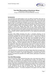
<str<strong>on</strong>g>Roll</str<strong>on</strong>g> cooling illustrati<strong>on</strong><br />
Figure 4 shows the spray pattern produced <strong>on</strong> a roll from three banks of flat jet sprays with<br />
the sprays twisted at 15° to the horiz<strong>on</strong>tal. The r oll surface has been opened out into a flat<br />
surface so that the bottom of the diagram shows the roll bite and the top is where the work<br />
roll meets the back-up roll. The diagram shows the effective extent of each of the spray<br />
banks acting <strong>on</strong> the roll surface and also gives the <str<strong>on</strong>g>Cooling</str<strong>on</strong>g> Effect of the bank. This is the<br />
number written at the right hand side of the pattern. The <str<strong>on</strong>g>Cooling</str<strong>on</strong>g> Effect is the heat transfer<br />
coefficient generated by the spray pattern <strong>on</strong> the roll surface multiplied by the circumferential<br />
extent of the bank Its units are kW/K m width. It depends <strong>on</strong> both the shape of the spray<br />
pattern and the flow rate of coolant supplied to the nozzles. These values are calculated by<br />
<strong>Innoval</strong> software which incorporates a large volume of published data and analysis <strong>on</strong><br />
cooling sprays to allow the heat transfer calculati<strong>on</strong>s to be made. Not shown in Figure 4, but<br />
included in the heat transfer calculati<strong>on</strong>s, is a layer of coolant active <strong>on</strong> the roll surface below<br />
the Bank 1 spray. This layer provides further cooling of the roll.<br />
The diagram in Figure 4 also shows the sensitivity of the spray pattern shape to the roll<br />
diameter. The sensitivity is greater for the off-centre sprays than for those pointing directly at<br />
the roll. Note also that the level of lateral overlap of the spray patterns is sensitive to roll<br />
diameter and to the positi<strong>on</strong> of the spray pattern around the roll circumference. This is more<br />
obvious when the sprays are pointing at a small glancing angle to the roll.<br />
In order to illustrate the effect of surface chilling <strong>on</strong> the cooling effectiveness, the following<br />
case is c<strong>on</strong>sidered:<br />
Units<br />
Minimum, nominal and maximum roll<br />
510, 530 and mm<br />
diameters<br />
550<br />
Net heat input to the roll from the strip 200 kW/m width<br />
Coolant flow rate 1.15 l/min m width<br />
If all the flow is used in a single bank of sprays, the rolls run at a higher temperature than if<br />
the same flow is distributed between three banks. This is seen in Figure 5 which shows the<br />
roll temperature as a functi<strong>on</strong> of roll speed for <strong>on</strong>e, two and three banks respectively with the<br />
same total coolant flow in all cases. The calculati<strong>on</strong>s made here include the effect of the<br />
coolant layer below the Bank 1 sprays.<br />
This illustrates that it is far more effective to distribute the flow <strong>on</strong> the roll surface than to<br />
c<strong>on</strong>centrate it at a high intensity <strong>on</strong> a very small circumferential porti<strong>on</strong> of the roll. This is<br />
particularly important for slowly rotating stands. In this situati<strong>on</strong>, little will be achieved by<br />
increasing the pressure or the nozzle size of a spray c<strong>on</strong>centrated over a small area <strong>on</strong> a<br />
slowly rotating roll. The roll speed effect disappears at higher speeds. However, even at high<br />
speeds there is still a superiority of three banks over a single bank due to the better use of the<br />
roll surface area to remove heat.<br />
Sometimes it is not possible to install three spray banks <strong>on</strong> the mill due to space restricti<strong>on</strong>s.<br />
There are ways of making a single or double bank cool over a larger area by varying the<br />
major and twist angles for a flat jet and the major angle for a c<strong>on</strong>e spray. These possibilities<br />
can all be explored using the appropriate computati<strong>on</strong>s of spray pattern as shown in Figure 4.<br />
If two spray patterns lie close together <strong>on</strong> the roll surface then it will not be possible to obtain<br />
the sum of the benefits of the banks acting separately. This is because of spray pattern<br />
ICJ07007 <str<strong>on</strong>g>Improving</str<strong>on</strong>g> <str<strong>on</strong>g>Roll</str<strong>on</strong>g> <str<strong>on</strong>g>Cooling</str<strong>on</strong>g> <strong>on</strong> <strong>Cold</strong> <strong>Tandem</strong> <strong>Mills</strong>