PolyWorks Case Study - CFD Analysis.pdf - Innovmetric Software
PolyWorks Case Study - CFD Analysis.pdf - Innovmetric Software
PolyWorks Case Study - CFD Analysis.pdf - Innovmetric Software

Create successful ePaper yourself
Turn your PDF publications into a flip-book with our unique Google optimized e-Paper software.
Audi, BMW, DaimlerChrysler, and<br />
Renault Turn to <strong>PolyWorks</strong> ® to Reduce<br />
the Time for <strong>CFD</strong> <strong>Analysis</strong> by up to 83%.<br />
A <strong>CFD</strong> analysis<br />
empowered by<br />
<strong>PolyWorks</strong> offers a<br />
series of benefits<br />
simply not achievable<br />
with physical<br />
wind tunnel simulations,<br />
and gives<br />
specialists of the<br />
automotive industry<br />
unprecedented<br />
insight into<br />
fluid flow behavior.<br />
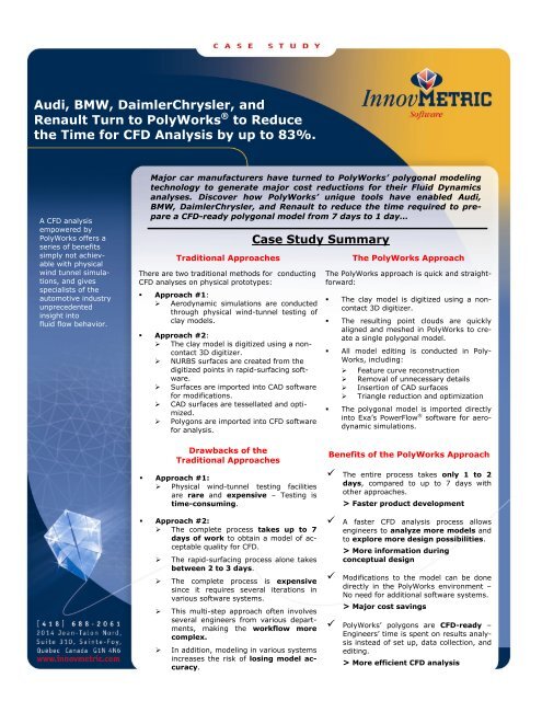
Major car manufacturers have turned to <strong>PolyWorks</strong>’ polygonal modeling<br />
technology to generate major cost reductions for their Fluid Dynamics<br />
analyses. Discover how <strong>PolyWorks</strong>’ unique tools have enabled Audi,<br />
BMW, DaimlerChrysler, and Renault to reduce the time required to prepare<br />
a <strong>CFD</strong>-ready polygonal model from 7 days to 1 day…<br />
Traditional Approaches<br />
There are two traditional methods for conducting<br />
<strong>CFD</strong> analyses on physical prototypes:<br />
• Approach #1:<br />
‣ Aerodynamic simulations are conducted<br />
through physical wind-tunnel testing of<br />
clay models.<br />
• Approach #2:<br />
‣ The clay model is digitized using a noncontact<br />
3D digitizer.<br />
‣ NURBS surfaces are created from the<br />
digitized points in rapid-surfacing software.<br />
‣ Surfaces are imported into CAD software<br />
for modifications.<br />
‣ CAD surfaces are tessellated and optimized.<br />
‣ Polygons are imported into <strong>CFD</strong> software<br />
for analysis.<br />
<strong>Case</strong> <strong>Study</strong> Summary<br />
The <strong>PolyWorks</strong> Approach<br />
The <strong>PolyWorks</strong> approach is quick and straightforward:<br />
• The clay model is digitized using a noncontact<br />
3D digitizer.<br />
• The resulting point clouds are quickly<br />
aligned and meshed in <strong>PolyWorks</strong> to create<br />
a single polygonal model.<br />
• All model editing is conducted in Poly-<br />
Works, including:<br />
‣ Feature curve reconstruction<br />
‣ Removal of unnecessary details<br />
‣ Insertion of CAD surfaces<br />
‣ Triangle reduction and optimization<br />
• The polygonal model is imported directly<br />
into Exa’s PowerFlow ® software for aerodynamic<br />
simulations.<br />
Drawbacks of the<br />
Traditional Approaches<br />
• Approach #1:<br />
‣ Physical wind-tunnel testing facilities<br />
are rare and expensive – Testing is<br />
time-consuming.<br />
• Approach #2:<br />
‣ The complete process takes up to 7<br />
days of work to obtain a model of acceptable<br />
quality for <strong>CFD</strong>.<br />
‣ The rapid-surfacing process alone takes<br />
between 2 to 3 days.<br />
‣ The complete process is expensive<br />
since it requires several iterations in<br />
various software systems.<br />
‣ This multi-step approach often involves<br />
several engineers from various departments,<br />
making the workflow more<br />
complex.<br />
‣ In addition, modeling in various systems<br />
increases the risk of losing model accuracy.<br />
Benefits of the <strong>PolyWorks</strong> Approach<br />
The entire process takes only 1 to 2<br />
days, compared to up to 7 days with<br />
other approaches.<br />
> Faster product development<br />
A faster <strong>CFD</strong> analysis process allows<br />
engineers to analyze more models and<br />
to explore more design possibilities.<br />
> More information during<br />
conceptual design<br />
Modifications to the model can be done<br />
directly in the <strong>PolyWorks</strong> environment –<br />
No need for additional software systems.<br />
> Major cost savings<br />
<strong>PolyWorks</strong>’ polygons are <strong>CFD</strong>-ready –<br />
Engineers’ time is spent on results analysis<br />
instead of set up, data collection, and<br />
editing.<br />
> More efficient <strong>CFD</strong> analysis
<strong>Case</strong> <strong>Study</strong><br />
A Revolution in the World of Fluid Dynamics <strong>Analysis</strong><br />
Fluid Flow analysis is the study of how fluids, such as air, liquids, and gases move in and<br />
around solid objects, such as airplane wings, automobile bodies, or petroleum pipelines. Most<br />
major car manufacturers worldwide face fluid flow problems in their design work, such as airflow<br />
over automobile surfaces measuring lift, drag, yaw, and friction. Typically, traditional fluid<br />
dynamics analysis are conducted through wind tunnel testing, an expensive and timeconsuming<br />
operation that requires well-trained technicians.<br />
The emergence of 3D digitizing technology has revolutionized the way to analyze Fluid Flow by<br />
opening the door to “Digital Wind Tunnel Testing”. The millions of data points captured by the<br />
non-contact 3D digitizers represent an excellent source of information for digitally simulating<br />
fluid flow, and replicating typical wind tunnel testing analysis at a fraction of usual cost and<br />
time.<br />
<strong>PolyWorks</strong> Empowers Digital Wind Tunnel <strong>Analysis</strong><br />
To perform powerful Digital Wind Tunnel <strong>Analysis</strong>, <strong>CFD</strong> software such as Exa’s Power-<br />
Flow ® necessitates polygonal models that meet strict requirements in term of accuracy, topology,<br />
size, etc. Not too long ago, several steps were required in order to prepare the model for<br />
<strong>CFD</strong> analysis, which could take up to 7 days of work. First, the digitized point cloud had to be<br />
transformed into NURBS surfaces using a reverse-engineering software system. The resulting<br />
surfaces were loaded into CAD software, and several editing operations such as feature reconstruction<br />
and removal of unnecessary details were conducted. The CAD model then had to<br />
be tessellated using another software package in order to recreate a meshed model. Most of<br />
the time, this tessellated polygonal model would necessitate other modifications in order to<br />
meet the 100,000-triangle target required for <strong>CFD</strong> analysis.<br />
“<strong>PolyWorks</strong> offers a straightforward approach which has changed drastically the preparation<br />
and optimization of the polygonal models for <strong>CFD</strong> analysis” said Dr. Hans-Peter Duwe from<br />
Duwe 3D <strong>Software</strong> in Germany. <strong>PolyWorks</strong> offers a wide set of polygon-editing tools that<br />
allows us to reconstruct feature curves, remove over-detailed features, and create closed<br />
polygonal models that can be used directly inside Exa’s PowerFlow. All operations can be<br />
conducted within one software solution, which reduces significantly the time and cost of the<br />
Fluid Flow analysis” he continued.<br />
Traditional Approach Versus <strong>PolyWorks</strong> Approach<br />
<strong>PolyWorks</strong><br />
Digitized<br />
Points<br />
<strong>CFD</strong><br />
<strong>Software</strong><br />
R-E<br />
<strong>Software</strong><br />
(NURBS)<br />
CAD<br />
<strong>Software</strong><br />
(Editing)<br />
Tessellation<br />
<strong>Software</strong><br />
(Meshing)<br />
<strong>PolyWorks</strong> advanced polygonal-editing tools let you directly create <strong>CFD</strong>-ready models
<strong>PolyWorks</strong>’ Complete Toolkit for Optimizing the Polygonal Model of an Automobile<br />
Create the<br />
Polygonal<br />
Model<br />
Edit the polygonal model for <strong>CFD</strong><br />
• Reconstruct feature curves<br />
• Fill all holes<br />
• Remove unnecessary details<br />
• Insert CAD surfaces<br />
Underbody<br />
Windows<br />
Lamps<br />
Reduce and<br />
Optimize<br />
Triangles<br />
1. Create the Polygonal Model<br />
• Car designers create a physical model using clay or other similar composite. The size of<br />
the car prototype may vary from full size to 1/2, 1/4, 1/10 reproductions.<br />
• The clay model is entirely digitized using a 3D digitizer.<br />
• The multiple scans are subsequently aligned by photogrammetry (for a full-sized model)<br />
or using <strong>PolyWorks</strong>’ unique best-fit method that quickly aligns scans using the geometric<br />
features of the object (for smaller objects).<br />
• The aligned point cloud is meshed in <strong>PolyWorks</strong> and a highly accurate polygonal model is<br />
created with between 500,000 and 1,000,000 triangles and a tolerance ranging from 10<br />
to 30 microns.<br />
Original polygonal model after<br />
meshing the digitized point clouds<br />
2. Edit the polygonal model for <strong>CFD</strong><br />
A) Reconstructing feature curves<br />
• One of the most important factors which influence the air flow of a model is the quality of<br />
its feature curves. Since 3D digitizers cannot capture sharp edges with great accuracy, editing<br />
work needs to be performed for the reconstruction. <strong>PolyWorks</strong> offers a powerful tool<br />
that detects and tracks feature curves and best-fits theoretical sharp edges. After the<br />
sharp edge curves have been extracted, they can be extended and intersected to create<br />
corners.<br />
1- Polygonal model before editing. 2- Best-fitted sharp edge curves.
3- Curves are extrapolated<br />
and magnetized.<br />
4- Curves and corners are inserted<br />
into the model to create perfect<br />
sharp edges and corners.<br />
B) Produce a compact and watertight polygonal mesh<br />
Here are the steps to create a compact and watertight model:<br />
• Filling holes produced during the digitizing phase:<br />
‣ <strong>PolyWorks</strong> offers various hole-filling tools to close the surface of a polygonal model.<br />
For holes of small and medium complexity, users can rely on an automatic hole-filling<br />
method that smoothly interpolates curved sets of triangles within a user-defined 3D<br />
bridging distance.<br />
‣ For larger and more complex holes, users can create composite Bézier surfaces or<br />
NURBS surfaces on top of the polygonal model and insert triangulated surfaces that<br />
follow the curvature of the object.<br />
• Deleting unnecessary features of the model:<br />
‣ The purpose of this operation is to keep the number of triangles as low as possible.<br />
<strong>CFD</strong> software such as Exa’s PowerFlow are optimized to process polygonal models of<br />
up to 100,000 triangles. To reduce the number of triangles, users can remove unnecessary<br />
triangles on highly-detailed areas of the model, such as grooves, air traps, etc.<br />
‣ User can then use composite Bézier surfaces or NURBS surfaces to reconstruct polygons<br />
in these areas.<br />
1- A curve is defined and inserted around<br />
the air trap under the front bumper.<br />
2- The area inside of the curve is<br />
selected and deleted.
3- A composite Bézier surface made of<br />
three patches is fitted to the boundary<br />
of the hole.<br />
4- The Bézier surface is tessellated and<br />
the curved set of polygons is connected<br />
to the surrounding triangles.<br />
C) Inserting CAD surfaces<br />
• Parts from an existing CAD model can be inserted to fill elements, such as the underbody,<br />
wheels, windshield, windows, and lights.<br />
• Bézier surfaces and NURBS surfaces can be used to fill the areas for which no CAD is<br />
available.<br />
1- A curve is defined and inserted on<br />
the boundary of the window.<br />
2- The area inside of the curve<br />
is selected and deleted.<br />
3- A tessellated surface obtained from<br />
a CAD model is inserted.<br />
4- The tessellated surface is connected<br />
to the surrounding triangles. The model<br />
is now watertight.
3. Reduce the number of triangles and optimize triangle orientation<br />
<strong>PolyWorks</strong> adaptive meshing technology enables the creation of “intelligent” polygonal models,<br />
preserving high resolution over edges and fillets while creating larger triangles in flat areas. To<br />
comply with Exa PowerFlow’s strict requirements, a polygonal model should:<br />
• Contain around 100,000 triangles<br />
• Not contain any triangles with bad aspect ratios (height/base)<br />
• Have triangles whose orientation follows the curvature of the object.<br />
<strong>PolyWorks</strong> offers advanced techniques to prepare a model that meets these requirements.<br />
Users can:<br />
• Set the reduction parameter as a target number of triangles.<br />
• Use a maximum edge length to prevent the creation of large triangles with poor aspect ratios.<br />
• Specify the edge detection angle for preserving feature lines.<br />
• Invoke a mesh optimization algorithm that aligns the triangle edges along the curvature flow.<br />
Edited model of 1,000,000 triangles<br />
before reduction and optimization.<br />
100,000-triangle model with triangle<br />
orientation following the curvature of<br />
the object<br />
Raise the <strong>CFD</strong> <strong>Analysis</strong> to Another Level with <strong>PolyWorks</strong><br />
Finally, an optimal polygonal model is exported by <strong>PolyWorks</strong> as an STL file to Exa’s PowerFlow<br />
for thorough <strong>CFD</strong> simulation. PowerFlow transforms the polygonal model into a mesh of Voxels<br />
to describe the solid surface, and calculates how particles are allowed to move and collide with<br />
each other and with the solid surface over a real-time period. A PowerFlow <strong>CFD</strong> analysis empowered<br />
by <strong>PolyWorks</strong> offers a series of benefits simply not achievable with physical wind tunnel<br />
simulations, and gives specialists of the automotive industry unprecedented insight into<br />
fluid flow behavior.<br />
Benefits from using <strong>PolyWorks</strong> to optimize <strong>CFD</strong> analysis:<br />
Minimizes the time for model preparation, which frees<br />
more time to better analyze results<br />
Provides more information during conceptual design<br />
Opens the doors to faster product development<br />
Brings superior quality products to market<br />
Generates major cost savings<br />
Model courtesy of<br />
Ford Motor Company<br />
For more information on this article please contact Sacha Villeneuve at svilleneuve@innovmetric.com<br />
<strong>PolyWorks</strong> is a registered trademark of InnovMetric <strong>Software</strong> Inc. PowerFlow is a registered trademark of<br />
Exa Corporation Inc. All other trademarks are property of their respective owners. www.innovmetric.com