Full text - ITC
Full text - ITC
Full text - ITC

Create successful ePaper yourself
Turn your PDF publications into a flip-book with our unique Google optimized e-Paper software.
• A box connecting points in a rectangular pattern of<br />
3 x 3 x 2;<br />
• A group of 9 high rise, flat roof buildings with a road<br />
along them;<br />
• A landscape with a road, a house and a lake;<br />
• A regular grid DTM pattern.<br />
A version with the same functionality for push broom scanner<br />
images is not yet finalized but a variety of spreadsheets with<br />
similar principles was produced to show:<br />
• A satellite orbiting a rotating globe,<br />
• The principle of a laser scanner,<br />
• Geometric transformations of square grid patterns,<br />
• A geocentric and a local coordinate system.<br />
The spreadsheets can be used directly to show the changing<br />
graphics in Excel, but the graphics can also be imported into<br />
other software, to prepare digital slides or illustrations in a <strong>text</strong><br />
file.<br />
MS Excel, MS Visual Basic and MS PowerPoint are products<br />
of Microsoft Corporation.<br />
Perspective View<br />
REALIZATION<br />
With the usual (photogrammetric) camera parameters the<br />
functionality was disappointing, as rotations of the camera<br />
made the object move out of the field of view. I therefore<br />
changed the calculations such, that the rotation axes did not<br />
pass through the projection center (O), but through the “viewed<br />
point” (M), which one can best choose in the middle of the<br />
object area. The projection center (O) is calculated such, that<br />
point M is in the camera axis, at a distance (D) from O, which is<br />
variable by the user. In addition to the three angles of rotation,<br />
the coordinates of “M” and the distance “D”, the user can<br />
specify:<br />
• The image coordinates of the image of point M (xm,<br />
ym), being the coordinates of the principal point,<br />
• The “image scale” (s), being the ratio between the<br />
principal distance and the “object distance” (D).<br />
This gave the functionality, that the object remained in view<br />
with angular changes, and the “object distance” controlled the<br />
amount of perspectivity in the image, without changing its size.<br />
r11<br />
⋅ (U − U<br />
M<br />
) + r12<br />
⋅ (V −VM<br />
) + r13<br />
⋅ (W − WM<br />
)<br />
x = D ⋅ s ⋅<br />
+ xm (1)<br />
r ⋅ (U − U ) + r ⋅ (V −V<br />
) + r ⋅ (W − W ) + D<br />
21<br />
r31<br />
⋅ (U − U<br />
M<br />
) + r32<br />
⋅ (V −VM<br />
) + r33<br />
⋅ (W − WM<br />
)<br />
y = D ⋅ s ⋅<br />
+ ym<br />
r ⋅ (U − U ) + r ⋅ (V −V<br />
) + r ⋅ (W − W ) + D<br />
where<br />
21<br />
M<br />
M<br />
22<br />
22<br />
M<br />
M<br />
x, y = image coordinates<br />
xm, ym = coordinates of principal point<br />
D = object distance<br />
s = image scale<br />
r ij = elements of rotation matrix<br />
U M , V M , W M = coordinates of “view point” (M)<br />
U, V, W = object coordinates of any point<br />
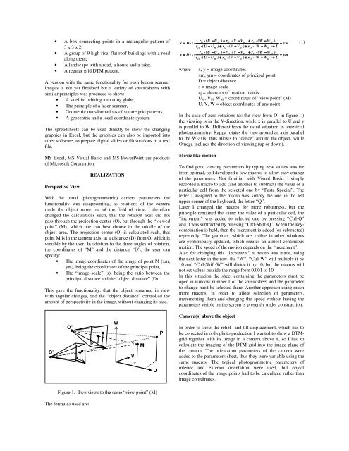
In the case of zero rotations (as the view from O’ in figure 1.)<br />
the viewing is in the V-direction, while x is parallel to U and y<br />
is parallel to W. Different from the usual situation in terrestrial<br />
photogrammetry, Kappa rotates the view around an axis parallel<br />
to the W-axis, thus allows to “dance” around the object, while<br />
Omega inclines the direction of viewing (up or down).<br />
Movie like motion<br />
To find good viewing parameters by typing new values was far<br />
from optimal, so I developed a few macros to allow easy change<br />
of the parameters. Not familiar with Visual Basic, I simply<br />
recorded a macro to add (and another to subtract) the value of a<br />
particular cell from the selected one by “Paste Special”. The<br />
letter I assigned to the macro was simply the one in the left<br />
upper corner of the keyboard, the letter “Q”.<br />
Later I changed the macros for more robustness, but the<br />
principle remained the same: the value of a particular cell, the<br />
“increment” was added to selected one by pressing “Ctrl-Q”<br />
and it was subtracted by pressing “Ctrl-Shift-Q”. When the keycombination<br />
is held, then the increment is added (or subtracted)<br />
repeatedly. The graphics, which are visible in other windows<br />
are continuously updated, which creates an almost continuous<br />
motion. The speed of the motion depends on the “increment”.<br />
Also for changing this “increment” a macro was made, using<br />
the next letter in the row, the “W”. “Ctrl-W” will multiply it by<br />
10 and “Ctrl-Shift-W” will divide it by 10, but the macros will<br />
not set values outside the range from 0.001 to 10.<br />
In this situation the sheet containing the parameters must be<br />
open in window number 1 of the spreadsheet and the parameter<br />
to change must be selected there. Another approach using much<br />
more macros, in order to allow selection of parameters,<br />
incrementing them and changing the speed without having the<br />
parameters visible on the screen is presently under construction.<br />
23<br />
23<br />
M<br />
M<br />
O’<br />
O”<br />
W<br />
V<br />
M<br />
U<br />
P<br />
Camera(s) above the object<br />
In order to show the relief- and tilt-displacement, which has to<br />
be corrected in orthophoto production I wanted to show a DTMgrid<br />
together with its image in a camera above it, so I had to<br />
calculate the imaging of the DTM grid into the image plane of<br />
the camera. The orientation parameters of the camera were<br />
added to the parameters sheet, thus they were variable using the<br />
same macros. The typical photogrammetric parameters of<br />
interior and exterior orientation were used, but object<br />
coordinates of the image points had to be calculated rather than<br />
image coordinates.<br />
Figure 1. Two views to the same “view point” (M)<br />
The formulas used are: