CTA - ITT Cannon
CTA - ITT Cannon
CTA - ITT Cannon

You also want an ePaper? Increase the reach of your titles
YUMPU automatically turns print PDFs into web optimized ePapers that Google loves.
The Centi Line - .075" Contact Spacing<br />
2D/<strong>CTA</strong><br />
2D/<strong>CTA</strong> CENTI-LOCTM Connectors Assembly Instructions<br />
The Double Density D/<strong>CTA</strong> CENTI-LOC Connectors are<br />
highly reliable and simple connectors to use. There<br />
are a few helpful suggestions that will assure complete<br />
satisfaction when followed:<br />
1. The following instructions should be followed.<br />
2. The proper crimp tool and locator (if required)<br />
must be used. These tools have been designed<br />
for use with this product. Substitutions of crimping<br />
equipment may result in connector failure at<br />
the assembly operation.<br />
3. After crimping a contact to a lead it is of vital<br />
importance that the proper tool be used to<br />
assure seating the contact in the insulator in the<br />
proper position. Any substitution of insertion<br />
tools may result in over or under insertion of the<br />
contact which may damage the retention system<br />
of the insulator.<br />
2D Assembly Instructions<br />
4. The female (socket) side of the connector has<br />
been designed with a controlled float to allow for<br />
ease of mating. To avoid reducing this float or<br />
causing a splaying of the contacts, any unnecessary<br />
strain caused by clamping the leads too close<br />
to the rear of the connector should be avoided.<br />
Use of recommended tooling together with proper<br />
assembly techniques will pay dividends in reliability<br />
and reduced costs.<br />
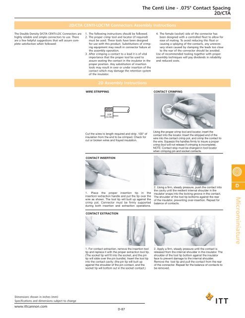
WIRE STRIPPING<br />
CONTACT CRIMPING<br />
.100<br />
(2.54)<br />
Cut the wires to length required and strip .100" of<br />
insulation from the end to be crimped. Check for<br />
cut or broken wires and frayed insulation.<br />
CONTACT INSERTION<br />
Using the proper crimp tool and locator, insert the<br />
contact into the locator. Insert the stripped end of the<br />
wire into the contact crimp pot, and crimp the contact to<br />
the wire. Squeeze the handles firmly to insure a proper<br />
crimp (tool will not release if crimping is incomplete).<br />
NOTE: Contact stop must be changed in tool locator<br />
when crimping pin and socket contacts.<br />
1. Place the proper insertion tip in the<br />
insertion/-extraction handle and put the tip over the<br />
wire as shown. The tool tip will butt up against the<br />
crimp pot. Connector must be firmly supported<br />
during both insertion and extraction operations.<br />
CONTACT EXTRACTION<br />
2. Using a firm, steady pressure, push the contact into<br />
the cavity until the resilient internal shoulder in the<br />
insulator snaps into the locking groove in the contact.<br />
The shoulder of the tool tip bottoms against the rear<br />
of the insulator, preventing over-insertion. Repeat for<br />
balance of contacts.<br />
D<br />
Microminiature<br />
1. For contact extraction, remove the insertion tool<br />
tip and replace it with the proper extraction tool tip.<br />
(The socket tip will fit into the socket, and the pin<br />
tip will slide over the pin bundle). Insert the tool tip<br />
into the contact cavity: (the pin tip will butt up<br />
against the shoulder of the pin contact, and the<br />
socket tip will bottom out in the socket contact.)<br />
2. Apply a firm, steady pressure until the contact is<br />
released from the internal shoulder in the insulator. The<br />
shoulder of the tool tip bottom against the insulator<br />
face to prevent damage to the internal shoulder.<br />
Remove the tool tip and pull the contact from the rear<br />
of the connector. Repeat for the balance of contacts to<br />
be removed.<br />
Dimensions shown in inches (mm)<br />
Specifications and dimensions subject to change<br />
www.ittcannon.com<br />
D-87

![Mil-C-22922 Class L [DS DSH] - ITT Cannon](https://img.yumpu.com/23591486/1/190x245/mil-c-22922-class-l-ds-dsh-itt-cannon.jpg?quality=85)
![Mil-DTL 5015 [MS K] - ITT Cannon](https://img.yumpu.com/23591484/1/190x245/mil-dtl-5015-ms-k-itt-cannon.jpg?quality=85)
![Mil-DTL 26482 Series I VG95328 [PVH] - ITT Cannon](https://img.yumpu.com/23591472/1/190x245/mil-dtl-26482-series-i-vg95328-pvh-itt-cannon.jpg?quality=85)

![Mil-DTL 26482 Series I [CPT] - ITT Cannon](https://img.yumpu.com/23591466/1/190x245/mil-dtl-26482-series-i-cpt-itt-cannon.jpg?quality=85)
![Mil-DTL [MS A-B] - ITT Cannon](https://img.yumpu.com/23591465/1/190x245/mil-dtl-ms-a-b-itt-cannon.jpg?quality=85)


![Mil-DTL 26482 Series I [KPT] - ITT Cannon](https://img.yumpu.com/23591441/1/190x245/mil-dtl-26482-series-i-kpt-itt-cannon.jpg?quality=85)
![MIL-DTL-24308 [TD1] - ITT Cannon](https://img.yumpu.com/23591440/1/190x245/mil-dtl-24308-td1-itt-cannon.jpg?quality=85)
![MIL-C-81659 [TDPX] - ITT Cannon](https://img.yumpu.com/23591438/1/190x245/mil-c-81659-tdpx-itt-cannon.jpg?quality=85)