- -l';) (DrqoNEErl
- -l';) (DrqoNEErl
- -l';) (DrqoNEErl

Create successful ePaper yourself
Turn your PDF publications into a flip-book with our unique Google optimized e-Paper software.
TX-s|E'clcltr<br />
5. CIRCUIT DESCRIPTIONS<br />
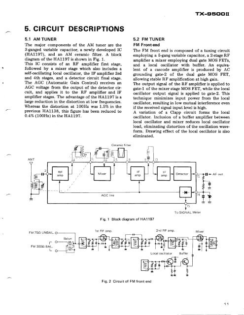
5.1 AM TUNER<br />
The major components of the AM tuner are the<br />
3-ganged variable capacitor, a newly developed IC<br />
(HA1197), and an AM ceramic filter. A block<br />
diagram of the HAlL97 is shown in Fig. 1.<br />
This IC consists of an RF amplifier first stage,<br />
followed by a mixer stage which also includes a<br />
self-oscillating local oscillator, the IF amplifier 3rd<br />
and 4th stages, and a detector circuit final stage.<br />
The AGC (Automatic Gain Control) receives an<br />
AGC voltage from the output of the detector circuit,<br />
and applies it to the RF amplifier and IF<br />
amplifier stages. The advantage of the HA1197 is a<br />
large reduction in the distortion at low frequencies.<br />
Whereas the distortion at 100H2 was 1.57o in the<br />
previous HA1138, this figure has been reduced to<br />
0.4Vo (LOOHz) in the HA1197.<br />
5.2 FM TUNER<br />
FM Front-end<br />
The FM front end is composed of a tuning circuit<br />
employing a 5-gang variable capacitor, a 2-stage RF<br />
amplifier a mixer employing dual gate MOS FETs,<br />
and a local oscillator with buffer. An equivalent<br />
of a cascode amplifier is produced by AC<br />
grounding gate-2 of the dual gate MOS FET,<br />
allowing stable RF amplification at high gain.<br />
The output signal of the RF amplifier is applied to<br />
gate-l of the mixer stage MOS FET, while the local<br />
oscillator output signal is applied to gate-2. This<br />
technique minimizes input power from the local<br />
oscillator, resulting in low mutual interference even<br />
if the received signal input level is high.<br />
A variation of a Clapp circuit forms the local<br />
oscillator. Inclusion of a buffer amplifier between<br />
local oscillator and mixer reduces local oscillator<br />
load, eliminating distortion of the oscillation waveform.<br />
Drawing effect of the local oscillator is also<br />
eliminated.<br />
Ceramic filter<br />
ANT<br />
AF out<br />
AGC line<br />
To SIGNAL Meter<br />
Fig. 1 Block diagram of HAl197<br />
FM 75O UNBAL.<br />
1st RF amp.<br />
2nd RF amp<br />
t-<br />
FM 3OOO BAL.<br />
L<br />
Local oscillator<br />
Fig. 2 Circuit of FM front end