EMC ENCLOSURES - Eldon
EMC ENCLOSURES - Eldon
EMC ENCLOSURES - Eldon

Create successful ePaper yourself
Turn your PDF publications into a flip-book with our unique Google optimized e-Paper software.
262<br />
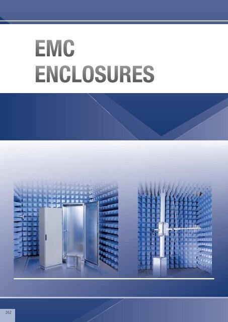
<strong>EMC</strong><br />
<strong>ENCLOSURES</strong>
MASE<br />
266<br />
IP 55, NEMA 12, IK 10<br />
H: 400-1000<br />
W: 400-800<br />
D: 210-300<br />
MCSE<br />
268<br />
IP 54, NEMA 12, IK 10<br />
H: 2000<br />
W: 800<br />
D: 600-800<br />
Accessories<br />
Side Panels<br />
Doors<br />
Separation plate<br />
Gasket<br />
Bottom and roof plates<br />
Baying kits<br />
Earthing<br />
Cable entry<br />
Fans<br />
270<br />
270<br />
271<br />
271<br />
272<br />
272<br />
273<br />
273<br />
274<br />
General Accessories<br />
286<br />
263
264
<strong>EMC</strong> Enclosures<br />
<br />
<br />
<br />
<br />
<br />
<br />
Based on the MultiFlex<br />
and MultiMount enclosures.<br />
Fully galvanized frame<br />
and body, only painted<br />
on the outside.<br />
Special conductive gasket<br />
on all panels and doors.<br />
No holes on the bottom plate<br />
for floor standing version<br />
and no gland plate for the<br />
wall mounting version ensures<br />
a good Faraday effect .<br />
Accessories that need a<br />
cut out to be mounted<br />
have a conductive surface<br />
to guarantee electrical<br />
continuity with the enclosure.<br />
Excellent attenuation levels.<br />
265
Electromagnetic (EMI) shielding<br />
MASE<br />
Wall mounting enclosures, single door.<br />
IP 55, NEMA 12 IK 10<br />
Technical data<br />
Material: Body: 1.2mm zinc plated steel /1.4mm<br />
MASE0606021R5 and above. Door: 1.2mm zinc plated steel /<br />
1.4mm MASE0606021R5 and above/1.8mm MASE1006026R5<br />
and above. Mounting plate: 2mm galvanized steel.<br />
Body: Folded and seam welded. Four 8.5mm diameter holes for<br />
wall fixing, pressed out in 20.4mm diameter x 2mm depressions<br />
to allow air circulation around the rear part of the enclosure.<br />
Door: Surface mounted with 130º opening. Concealed removable<br />
hinges with captive pin. Hinges can be mounted to allow left or<br />
right hand opening. From size MASE0505021R5 and above there<br />
are two removable mounting profiles on the door. Sealing is<br />
ensured by a conductive polyurethane <strong>EMC</strong> gasket.<br />
Lock: Chrome plated double-bit lock with 3mm insert and 90º<br />
movement. 1000mm high enclosures and above have<br />
espagnolette three point locking system.<br />
Mounting plate: The mounting plate is marked vertically at<br />
10mm intervals for easy horizontal positioning of equipment. On<br />
the top and bottom are holes to facilitate cable fixing.<br />
Fixed onto M8 press welded studs to the rear of the enclosure. All<br />
sides from 800mm and above are strengthened by folded edges.<br />
By using the AMG accessory the mounting plate can be adjusted<br />
to any depth.<br />
Gland Plate Opening: No gland plate opening for a maximum<br />
EMI protection.<br />
Earthing: The door is earthed by means of a separate earthing<br />
stud M8.<br />
Finish: RAL 7035 structure powder coating on the outside only.<br />
Protection: Complies with IP 55, NEMA 12, IK 10.<br />
Delivery: Zinc plated enclosure body and door, painted on the<br />
outside. Door equipped with EMI conductive gasket. Two door<br />
mounting profiles from size MASE0505021R5 and above.<br />
Earthing facilities.<br />
266<br />
<strong>EMC</strong> Shielded Enclosures<br />
Visit our website at www.eldon.com
Electromagnetic (EMI) shielding<br />
MASE, IP 55, NEMA 12 IK 10<br />
Enclosure dimension<br />
Mounting plate dimension<br />
H W D h w d Size Type Openings N° of locks Weight Part No.<br />
400 400 210 370 350 192 310x96 2 1 1 8,6 MASE0404021R5<br />
600 210 370 550 192 510x96 4 1 1 12,2 MASE0406021R5<br />
600 600 210 570 550 192 510x96 4 1 2 21 MASE0606021R5<br />
1000 800 300 970 750 282 310x96 2 2 1* 47 MASE1008030R5<br />
Product range MAS<br />
All the MAS standard sizes are available in <strong>EMC</strong> version on request.<br />
MASE: From 200/200/155mm to 1200/800/400mm.<br />
e.g. MASE0606021R5, <strong>EMC</strong> single door enclosure 600x600x210mm<br />
For more details please see MAS table.<br />
Shielding Effectiveness<br />
Shielding Effectiveness for <strong>Eldon</strong> wall mounting enclosures MAS, MASE.<br />
<strong>EMC</strong> attenuation tested according to VG 95 373 part 15.<br />
E: Field of attenuation<br />
SE (dB)<br />
H: Field of attenuation<br />
Frequency (MHz)<br />
SE (dB)<br />
SE_ELDON-MASE Magnetic Field<br />
SE_ELDON-MASE Electric Field<br />
SE_ELDON-MAS Magnetic Field<br />
SE_ELDON-MAS Electric Field<br />
Trend line<br />
Product specifications, CAD drawings and information available on the website<br />
<strong>EMC</strong> Shielded Enclosures<br />
267
Electromagnetic (EMI) shielding<br />
MCSE<br />
Combinable version, single door.<br />
IP 54, NEMA 12, IK 10<br />
Technical data<br />
Material: Frame: 1.5mm/1.75mm zinc plated steel. Door: 2mm<br />
zinc plated steel. Rear, roof and side panels: 1.35mm zinc plated<br />
steel. Mounting plate: 2.7mm galvanized steel. Bottom plates:<br />
1mm galvanized steel.<br />
Frame: Seam welded reversed open profiles with 25mm hole<br />
pattern according to DIN 43660. Including integrated external<br />
hole pattern.<br />
Door: Surface mounted with hinges allowing left or right hand<br />
opening. Including door frame with 25mm hole pattern. Sealing is<br />
attained by a conductive polyurethane <strong>EMC</strong> gasket.<br />
Rear panel: Fitted by M6 torx screws. Standard facilities for rear<br />
door mounting.<br />
Side panels: Supplied as an accessory.<br />
Roof panel: Removable.<br />
Lock: Espagnolette 4-point locking system. Does not interfere<br />
with the enclosure inner space. Standard double-bit lock with<br />
3mm pin. Can be exchanged for standard inserts or Eurocylinder,<br />
T- or swing handle locking system.<br />
Mounting plate: Double folded and slides into position.<br />
Adjustable in depth by steps of 25mm. In the enclosure delivery,<br />
mounting plate is attached on the outside of the package.<br />
Bottom plates: Consists of three pieces. For 800mm deep 4<br />
pieces.<br />
Earthing: All panels are earthed through their fittings and are<br />
equipped with a separate earthing stud.<br />
Finish: RAL 7035 structure powder coating on the outside only.<br />
Protection: Complies with IP 54, NEMA 12. IK 10.<br />
Delivery: Frame with fitted door, rear panel, roof panel, bottom<br />
plates, mounting plate and door frame. Delivery also includes<br />
earthing bolts and EMI conductive combination gasket. Delivered<br />
on a pallet with same width as the enclosure to allow suiting<br />
without removal. All packing material recyclable.<br />
Note: In 400mm wide enclosures, the mounting plate, bottom<br />
plates and door frame are not included. * Also available in<br />
stainless steel (MCSSE).<br />
268<br />
<strong>EMC</strong> Shielded Enclosures<br />
Visit our website at www.eldon.com
Electromagnetic (EMI) shielding<br />
MCSE, IP 54, NEMA 12, IK 10<br />
Enclosure dimension<br />
Mounting plate dimension<br />
H W D h w d Weight Part No.<br />
2000 800 600 1894 694 559 132 MCSE20086R5<br />
800 1894 694 759 139 MCSE20088R5<br />
* All the MCS standard sizes are available in <strong>EMC</strong> version on request including other dimensions.<br />
For <strong>EMC</strong> sidepanels see SPME.<br />
Shielding Effectiveness<br />
Shielding effectiveness for <strong>Eldon</strong> floor standing enclosures MCS, MCSE.<br />
<strong>EMC</strong> attenutation tested according to VG 95 373 part 15<br />
E: Field of attenuation<br />
H: Field of attenuation<br />
Frequency (MHz)<br />
Labyrinth protection of the<br />
MultiFlex enclosure line<br />
Shielding Effectiveness<br />
Standard Multi-Flex, Floor standing enclosures, MCS<br />
EMI adapted Multi-Flex, Floor standing enclosures, MCSE<br />
Product specifications, CAD drawings and information available on the website<br />
<strong>EMC</strong> Shielded Enclosures<br />
269
Electromagnetic (EMI) shielding<br />
SPME, Side panels<br />
DGCE, Glazed door (61%)<br />
Description: For covering the sides of the MCSE enclosures.<br />
Equipped with a conductive gasket providing both <strong>EMC</strong>/IP<br />
protection.<br />
Material: 1.35mm zinc plated steel.<br />
Finish: RAL 7035 structure powder coating on the outside<br />
only.<br />
Protection: Compiles with IP 54, NEMA12.<br />
Pack quantity: 2 panels with mounting accessories.<br />
H D Part No.<br />
2000 600 SPME2006R5<br />
800 SPME2008R5<br />
*Other sizes available on request<br />
Description: Standard door fitted with clear safety glass to<br />
view the inside of the enclosure. Equipped with double-bit<br />
3mm lock system and door frame. Allows all options of the<br />
locking program. Sealing is maintained by a conductive<br />
polyurethane <strong>EMC</strong> gasket. To ensure the EMI effectiveness a<br />
mesh wire is placed behind the glass window with a clearance<br />
percentage of 61%. Use hinge kit DMK if not for replacement<br />
of standard door.<br />
Material: Frame: 2mm zinc plated steel. Viewing area: 3mm<br />
clear safety glass.<br />
Finish: RAL 7035 structure powder coating on the outside<br />
only.<br />
Protection: Complies with IP 54, NEMA12, IK 10.<br />
Mounting requirement: If no door was fitted previously use<br />
hinge kit DMK01.<br />
Pack quantity: 1 piece.<br />
H W h w Part No.<br />
2000 800 1776 615 DGCE2008R<br />
Shielding Effectiveness<br />
<strong>EMC</strong> attenuation tested according to VG 95 373 part 15<br />
EMI adapted MultiFlex, Floor standing enclosures, MCSE<br />
270 <strong>EMC</strong> Shielded Enclosures Visit our website at www.eldon.com
Electromagnetic (EMI) shielding<br />
SPD <strong>EMC</strong>, Separation plates<br />
SPDEG, Gasket for <strong>EMC</strong> shielding<br />
Description: To obtain an <strong>EMC</strong> shielded section in a suited<br />
panel in combination with the separation plate SPD.<br />
Material: Polyurethane foam with conductive layer. (UL94HB)<br />
Protection: Complies with IP 43, NEMA1.<br />
Pack quantity: 6m.<br />
Description: Separates two bayed enclosures. To be fixed<br />
with combining kit CCJ. To achieve IP 43, NEMA1 a neoprene<br />
gasket SPDG 01 can be fixed to the panel. For EMI separation<br />
the SPDEG gasket must be fitted.<br />
Material: 1.5mm zinc plated steel.<br />
Mounting requirement: Add CCJ brackets for mounting.<br />
Pack quantity: 1 piece.<br />
Part No.<br />
SPDEG01<br />
D<br />
Part No.<br />
600 SPD2006<br />
800 SPD2008<br />
Shielding Effectiveness<br />
<strong>EMC</strong> attenuation tested according to VG 95 373 part 15<br />
Shielding effectiveness for <strong>Eldon</strong> floor standing<br />
enclosure separation plate SPD<br />
Product specifications, CAD drawings and information available on the website <strong>EMC</strong> Shielded Enclosures 271
Electromagnetic (EMI) shielding<br />
CVB <strong>EMC</strong>, Ventilated bottom plates<br />
CVRE, EMI Ventilation roof<br />
.<br />
Description: Three piece bottom plates. Can be used in<br />
combination with a ventilated plinth PV. 33% ventilation.<br />
Material: 1.5mm perforated zinc plated steel.<br />
Pack quantity: 3 pieces with mounting material.<br />
Mounting requirement: Use in combination with ventilated<br />
plinths PV.<br />
Description: Inner ventilation roof plate for a high EMI<br />
protection. Mounted directly into the frame of the enclosure.<br />
Can be used in combination with the CVR ventilation roof, CFR<br />
fan roof plate or the spacers to raise a standard roof CVK15.<br />
33% ventilation.<br />
Material: 1.5mm zinc plated steel.<br />
Finish: Non painted zinc plated steel.<br />
Pack quantity: 1 piece with mounting accessories.<br />
W D Part No.<br />
800 600 CVRE0806<br />
800 CVRE0808<br />
For enclosure<br />
D<br />
Part No.<br />
600 CVB0806<br />
800 CVB0808<br />
CCJ, Internal baying kit<br />
.<br />
Shielding Effectiveness<br />
<strong>EMC</strong> attenuation tested according to VG 95 373 part 15.<br />
Description: Mounted to the frame profile. Can be used both<br />
on the vertical and the horizontal frame profile.<br />
Material: 3mm zinc plated steel.<br />
Pack quantity: 12 brackets with mounting accessories.<br />
Mounting requirement: IP 43, NEMA 1 sealing can be<br />
obtained by using SPDG gasket. For internal baying, use CCM<br />
brackets.<br />
Shielding effectiveness for top and bottom plates of<br />
the MultiFlex range<br />
Part No.<br />
CCJ12<br />
272 <strong>EMC</strong> Shielded Enclosures Visit our website at www.eldon.com
ECFE, Earthing strap<br />
.<br />
Electromagnetic (EMI) shielding<br />
CBPE, <strong>EMC</strong> connection bottom plate<br />
.<br />
Description: For earthing and potential compensation<br />
between panels, parts and enclosure' s frame. Length: 300mm.<br />
Material: Tinned electrolytic cooper 0.15mm wire.<br />
Working temperature: Up to 105ºC.<br />
Pack quantity: 10 pieces.<br />
Mounting requirement: Add connection set ECF for fixing<br />
strap to painted frame.<br />
Description: Replaces two parts of the standard three or four<br />
piece bottom plates. Due to the hammer head cones, EMI<br />
cables can be directly earthed to the bottom plate keeping the<br />
"Faraday cage".<br />
Material: 1.5mm zinc plated steel.<br />
Pack quantity: 2 pieces with EMI gasket and mounting<br />
accessories.<br />
Cross sectional area Holes diam. Current (A) Part No.<br />
16mm² 8.5 120A ECFE1630<br />
25mm² 10.5 150A ECFE2530<br />
BGE, <strong>EMC</strong> cable entry and bottom plate<br />
gasket<br />
For enclosure<br />
W D Part No.<br />
600 600 CBPE0606<br />
800 CBPE0608<br />
800 600 CBPE0806<br />
800 CBPE0808<br />
CABP, Cable fixing bar<br />
.<br />
Description: The bottom of the enclosure is sealed by the use<br />
of an adhesive gasket applied to the frame around the bottom<br />
opening. The cables are sealed by the addition of adhesive<br />
foam placed between the bottom plates. The elasticity and the<br />
size of this foam ensures a tight seal around most cables.<br />
Added conductive material provides a good contact to shield<br />
the transfer of electro-magnetic radiation.<br />
Pack quantity: 1.6m adhesive <strong>EMC</strong> gasket for cable entry and<br />
6m adhesive bottom plate gasket. For 1600mm wide<br />
enclosures please order 2 sets.<br />
Description: Suspended below the bottom plates, thereby<br />
maximizing the full usable space in the enclosure. Holds<br />
standard cable clamps CAC to secure incoming cables. Fully<br />
adjustable in depth. When <strong>EMC</strong> shielded earthing cables are<br />
connected to the support bar the Faraday effect will be kept<br />
intact for maximum EMI shielding.<br />
Material: 2mm zinc plated steel.<br />
Pack quantity: 2 bars with mounting accessories. For<br />
1200mm wide, 4 bars with mounting accessories.<br />
Mounting requirement: Add CAC clamps depending on<br />
diameter of cable.<br />
Part No.<br />
BGE01<br />
W<br />
Part No.<br />
400 CABP400<br />
500 CABP500<br />
600 CABP600<br />
800 CABP800<br />
1000 CABP1000<br />
1200 CABP1200<br />
Product specifications, CAD drawings and information available on the website <strong>EMC</strong> Shielded Enclosures 273
Electromagnetic (EMI) shielding<br />
<strong>EMC</strong>, Shielded Filter Fans<br />
<strong>EMC</strong>, Filter Fans and Exhaust Filters<br />
When using fan and filter units in an enclosure, vent slots have<br />
to be made. This immediately results in a leakage in terms of<br />
the <strong>EMC</strong>-regulation. If <strong>EMC</strong> requirements are appropriate,<br />
special <strong>EMC</strong>-protected filter and fan units must be used. <strong>Eldon</strong><br />
offers a "click-in" solution for which no screws are required! To<br />
prevent corrosion attacking the <strong>EMC</strong>-screen, the outer parts of<br />
the filter and fan units are mounted with a stainless steel frame<br />
in combination with Beryllium copper contact strips. Thus<br />
combining a high corrosion resistance with a high attenuation<br />
level.<br />
Technical features:<br />
- A wide air flow range from 61 m3/h to 845m3/h.<br />
- No screws are required for fixing the units.<br />
- Only square cut outs required.<br />
- Units only protrude 6 mm from the enclosure surface.<br />
- The filter mat can be quickly changed without dismounting the<br />
complete unit.<br />
- Material conforms with the requirements of ISO 14000<br />
(Environmental - Management System).<br />
- Housing material is self extinguishing.<br />
Screening effectiveness Thermal Management Filter and Fans<br />
EFE/EFAE:<br />
<strong>EMC</strong> attenuation measured according to EN 50 147 - 1 (1996).<br />
274 <strong>EMC</strong> Shielded Enclosures Visit our website at www.eldon.com
Electromagnetic (EMI) shielding<br />
Shielded Filter Fans<br />
IP 54 Thermal Management<br />
Our <strong>EMC</strong>-shielded filter fans affect the <strong>EMC</strong> shielding of your<br />
enclosure as follows:<br />
Damping at 30 MHz approx. 71 dB<br />
Damping at 400 MHz approx. 57 dB<br />
Measured according to EN 50 147 - 1 (1996)<br />
No extensive extra work on the installation cut out<br />
- no copper band or similar auxiliary materials to glue in place<br />
- no need to scratch away layers of material to ensure surfaceto-surface<br />
contact<br />
1. Surface-to-surface contact made via edge of the cut out for<br />
the filter fan or exhaust filter<br />
2. Innovative surface-to-surface contact along the edge of the<br />
cut out makes mounting a simple task<br />
3. Reliable surface-to-surface contact by means of specially<br />
shaped contact springs on screen grid<br />
4. Low environmental impact due to use of separate screen<br />
grids made of stainless steel (1.4301)<br />
5. Low environmental impact because grid plates and contact<br />
surfaces are in one piece; beryllium copper band is not<br />
necessary to provide contact, and materials can be separated<br />
for easy recycling.<br />
Shielding effectiveness Thermal Management Filter and Fans EFE/EFAE:<br />
<strong>EMC</strong> attenuation tested according to EN 50 147- (1996)<br />
E: Field of attenuation<br />
H: Field of attenuation<br />
Product specifications, CAD drawings and information available on the website <strong>EMC</strong> Shielded Enclosures 275
Electromagnetic (EMI) shielding<br />
1.1.The mechanism of Electromagnetic Interference (EMI)<br />
The definition of <strong>EMC</strong><br />
The council of the European Union defines <strong>EMC</strong> in Article 4 of<br />
their "council directive on the approximation of the lawsof the<br />
Member States relating to Electromagnetic Compatibility (89/<br />
336/EEC)" as property of an "apparatus":- The apparatus shall<br />
be so constructed that: the electro-magnetic disturbance it<br />
generates does not exceed a level allowing radio and<br />
telecommunications equipment andother apparatus to operate<br />
as intended" (emission requirement)- The apparatus has an<br />
adequate level of intrinsic immunityof electromagnetic<br />
disturbance to enable it to operate as intended" immunity<br />
requirement. This is a very broad definition. The customary<br />
route to compliance is the application of standards. There are<br />
product standards, applicable to a specific product type(e.g.<br />
lighting) and, when not available, there are "generic standards"<br />
that can be used. When your product passes all required tests<br />
this provides the "presumption of compliance".<br />
What can you do?<br />
The problem is that there is no direct relation between the tests<br />
to establish the fact of "<strong>EMC</strong>" and the measures you can take<br />
to behave satisfactory in that respect. What you need is some<br />
basic knowledge on the mechanisms of electromagnetic<br />
interference.<br />
Differential and common-mode currents<br />
All electric currents run in loops. When you measure current in<br />
a wire there must be a return current some whereto the original<br />
source. The currents that determine the functional behaviour of<br />
a design are called "differential-mode"currents (dm-currents for<br />
short). There is another type, however: 98% of all interference<br />
problems are caused by common-mode currents (cmcurrents).<br />
It depicts an intended o rdesired current loop formed<br />
by a cable: a signal and a return line transferring some current<br />
from a source Ug to a load RLand back. This is a differentialmode<br />
current, which means that, if we would use a current<br />
probe around the cable to measure the net current passing<br />
through the probe,we would find a zero value: all currents<br />
going from the source to the load return via the intended return<br />
conductor.Consider the circuit in figure 1<br />
When a portion of the return current takes the alternative path,<br />
we will be able to measure a net amount of current with a<br />
current probe around the cable. Figure 3.<br />
These undesired currents are not intended by the designer of<br />
the equipment and, worse, usually not included into hisan<br />
alyses. It is these "forgotten" currents that create most of the<br />
sometimes damaging interference in electronic systems.<br />
Cables convert from dm to cm and back<br />
Cables or, more generally, interconnections have the property<br />
to convert differential mode currents into common-mode<br />
currents and vice-versa. This property iscalled "transferimpedance".<br />
This is the basic phenomenon which is<br />
responsible for electromagnetic interference.<br />
The rest is "related topics". For instance: all currents are<br />
accompanied by a magnetic field. The picture in figure 4 shows<br />
a two wire cable. Each wire carries the same current but their<br />
directions are opposite.<br />
It depicts an intended ordesired current loop formed by a<br />
cable: a signal and areturn line transferring some current from<br />
a source Ug to aload RL and back. this is a differential-mode<br />
current, whichmeans that, if we would use a current probe<br />
around thecable to measure the net current passing through<br />
the probe,we would find a zero value: all currents going from<br />
thesource to the load return via the intended return conductor.<br />
Complications arise, when there are alternative return<br />
pathsavailable e.g. via connections for safety grounding.In that<br />
case there is a choice for the return current: Figure 2.<br />
The magnetic field lines belonging to each of them "add up "<br />
between the two wires and "subtract" outside that area.<br />
Assuming ideal conditions, the combined magnetic field<br />
magnitudes could be reduced to zero if it were possible to<br />
position the two wires "on top of" each other, exactly centred.<br />
The then equal but opposite fields at any position would<br />
exactly cancel ("coax" situation)!<br />
In any practical situation there will, however, be some distance<br />
between the two wires. This means that some amount of<br />
field will be measurable outside the cable. This field inturn<br />
induces currents in any conducting loop in the neigh-bourhood.<br />
This includes the loop formed by the cable itself and any<br />
alternative return conductor (a "common-mode" or groundloop)!<br />
Figure 5.<br />
276 <strong>EMC</strong> Shielded Enclosures Visit our website at www.eldon.com
Electromagnetic (EMI) shielding<br />
This alternative conductor could be the machine' s<br />
structure,safety grounding provisions, the enclosure wall or<br />
othercables. This (induced) current in the usually larger loop is<br />
a common-mode (cm) current. Transfer impedance is<br />
aproperty of a complete interconnection: cable plus<br />
connectors, patch panels etc. from source to load!<br />
The properties of a very good cable can be ruined by a lousy<br />
finishing e.g. the infamous "pig-tail" construction on shielded<br />
cables. Figure 6.<br />
2. Interference sources and susceptibility threats<br />
Thus, interconnections are our sole concern for all <strong>EMC</strong><br />
related issues. From printed circuit board traces to<br />
systemcabling! We can divide the threats to our systems into<br />
"man-made" and "natural". Actual interference is always a<br />
susceptibility problem: the disturbed system is unable to cope<br />
with the fields or currents that threaten it. Whether the system<br />
should be able to cope with them is determined by the<br />
prescribed levels in the <strong>EMC</strong> standards! If the system is too<br />
susceptible (civil standards call it "insufficient immunity") you<br />
will have to improve it by working on the various<br />
interconnections by improving their transfer-impedance. If the<br />
system is ok., the interference source has to be located and a<br />
similar process must be carried out to reduce its "emissions"<br />
Man-made threats<br />
Interference with a continuous character<br />
Most interference emerges from equipment either your own<br />
system or the neighbour' s. Well known sources of highfrequency<br />
fields are transmitters from public services to GSM<br />
telephones. Notably the portable telephones are a threat since<br />
they are mobile and can get very close to the susceptible<br />
equipment. Fields related to transmitters and other high<br />
frequency equipment are in the range from 1 to 100 Volts per<br />
meter (Electric field value). Typically 10 V/m or an industrial<br />
environment (but: no guarantee)! As a rule of thumb each ltper-meter<br />
of field gives rise toa common-mode current of 10<br />
mA in an unprotected able.100 mA of cm-current is considered<br />
a critical value inprocess control installations. Apart from<br />
intentional transmitters there are the unintentional transmitters<br />
formed by interconnections hich generate common-mode<br />
currents and corresponding fields. A high-frequency current in<br />
a cable with inadequate transfer-impedance is the common<br />
cause.<br />
This common-mode current can either flow directly on a<br />
sensitive cable (e.g. from analogue sensors) or create a high<br />
frequency electromagnetic field which induces common-mode<br />
currents in sensitive cables. Interference with an intermittent<br />
character A special type of interference are "impulsive<br />
disturbances" caused e.g. by switching inductive loads.<br />
Examples are relays, frequency converter/motor combinations<br />
and switched mode power supplies. When inadequately<br />
"snubbered", high peak values in voltage and current are<br />
reached when the load is switched. These currents travel<br />
through the interconnecting cables and are converted into<br />
common-mode currents. The interference mechanism is, of<br />
course, identical to the continuous case but due to the<br />
intermittent character, it can be more difficult to locate the<br />
source of the problem. Common-mode currents from these<br />
sources can be considerate: several hundreds of millions<br />
amperes especially when relay contacts degrade over time.<br />
Natural sources of interference<br />
Natural sources are lightning and electrostatic discharge<br />
(ESD). The phenomena are related. In either case a (static)<br />
electric discharge occurs. In the lightning case a large circuit<br />
is involved with dimensions reaching many kilometres. In the<br />
ESD case, there is usually a person carrying the charge and<br />
discharging into a piece of equipment by touching it.<br />
The lightning stroke is a high-energy phenomenon with a<br />
relatively low frequency character. Consequently most<br />
interference is transferred by conduction. ESD is a high<br />
frequency phenomenon with a lower energy content. High<br />
frequencies, however, can travel "through air" (capacitive<br />
effect) and the corresponding damaging current in<br />
the equipment cannot easily be diverted. If there is a<br />
susceptible component in its path: too bad for the component.<br />
Common-mode currents as a result from these natural sources<br />
can reach very high values.<br />
Amperes are not uncommon. (A direct lightning stroke typically<br />
has 50 kA -i.e. 50000 A-, ESD from 5 -40 A)<br />
3. Measures to improve compatibility<br />
Packaging of equipment can have a major effect on the<br />
behaviour in electromagnetically "hostile" environments. In the<br />
following sections several approaches are shown. Most of<br />
them are very cheap when considered at the design stage.<br />
Later in the lifecycle protective measures becomescarce and<br />
more expensive.<br />
Recognize common-mode or ground loops<br />
Split up cables into categories<br />
All <strong>EMC</strong> problems (well, 98%) are common-mode problems.<br />
Try to develop an instinct for common-mode or ground-loops.<br />
Once found, they can be treated followingthe systematic<br />
approach given below. A first example was given in figure 5, a<br />
slightly more complex example is shown in figure 7.<br />
Product specifications, CAD drawings and information available on the website <strong>EMC</strong> Shielded Enclosures 277
Electromagnetic (EMI) shielding<br />
Several cable types can be observed in this diagram. It is<br />
usually helpful to draw a simplified diagram showing<br />
equipment as circles with interconnecting conductors.<br />
Do not forget to include power, "ground" and machine structure<br />
as conductors! In the diagram of figure 8, several cable types<br />
can be recognized:<br />
- Cables with large and/or high frequency currents. Indicate<br />
this type using a red colour or the letter "E" for Emission: due<br />
to transfer-impedance it will generate possibly large commonmode<br />
currents.<br />
Example: the cable between frequency converter and motor<br />
- Cables that neither generate nor are susceptible to commonmode<br />
currents. Indicate them using a blackcolour or the letter<br />
"N" for Neutral.<br />
Example: power cables, machine or building structure,metal<br />
piping etc.<br />
- Cables that carry small analog signals or are otherwise<br />
sensitive to interference by common-mode currents across<br />
them. Indicate this type using a green colour or the letter "S"<br />
for Susceptible.<br />
Example: sensor cabling, RS-485 line, PLC/frequency<br />
converter control cable. Figure 9.<br />
Of course, more detailed distinctions can be made. Books on<br />
<strong>EMC</strong> generally use five to seven cable categories.<br />
The RS-485 cable in our example can be susceptible to cmcurrents<br />
from the motor cable but could be an interference<br />
source to sensitive analog signals! The three categories used<br />
here are only used to demonstrate the principle: our effort<br />
should be focused on keeping the emission sources separated<br />
from the sensitive cables!<br />
Reduce your sensitivity to cm-currents<br />
Keep interconnections short<br />
The first thing we can do is keep cable lengths short. All<br />
interference is ultimately coupled through transfer-impedance,<br />
the cable property that converts common-modecurrents to<br />
differential and vice versa. This effect increases with cable<br />
length! The shorter the cable, the smaller the effect. For that<br />
reason interference risks in our examplein figure 8 and figure 9<br />
would go down dramatically if we could manage to build the<br />
frequency converter right down on the motor! No cable length<br />
to speak of, no generation of common-mode currents. Of<br />
course, external fields remain as threats to our sensitive<br />
cables.<br />
Shield cables<br />
The conversion of differential-mode to common-mode currents<br />
and vice-versa can be reduced considerably by shielding the<br />
cables. In other words, this reduces their transfer impedance.<br />
It is important to connect the shielding on both ends to the<br />
equipment the cable connects. The best way to do this is using<br />
an <strong>EMC</strong> gland (discussed later) or metal connector shell i.e. by<br />
providing a contact over 360° between the braid and the<br />
enclosure wall itenters. The measures described below are,<br />
nevertheless, appropriate when considerable distances have<br />
to be covered.<br />
Reduce common-mode loop areas<br />
As a next step it is useful to reduce the areas of (all) commonmode<br />
loops detected. This does not readilyremove the<br />
common-mode currents in our loops but at leastthe field<br />
outside the loop will be reduced by this action.Further, it makes<br />
the loop less sensitive to external fields.The reduction can be<br />
achieved by routing the categorymarked "black" or "N"<br />
alongside the green and red ones.Figure 10.<br />
In our specific situation the black conductor between motor<br />
and sensors is the machine structure! It is cumbersome to<br />
bend it alongside the cables so a solution where the cables are<br />
routed along the structure is more appropriate here! But, as<br />
long as the enclosure containing the PLC and frequency<br />
converter cannot be built on the machine structure itself, this<br />
will remain difficult. So we will have to look for other<br />
alternatives.<br />
<strong>EMC</strong> grounding: current boundaries<br />
For that we will take our next step first: try to divert the<br />
threatening common-mode currents away from the sensitive<br />
cables i.e. provide an alternative path for them.This alternative<br />
is called a "current boundary" or referenceconductor.<br />
Figure 11.<br />
278 <strong>EMC</strong> Shielded Enclosures Visit our website at www.eldon.com
Electromagnetic (EMI) shielding<br />
In the situation of figure 10, this would call for a (high<br />
frequency) connection between the bottom end of the red<br />
cable and the black conductor next to it. Of course, the closer<br />
the current boundary is to the end of the cable, the larger the<br />
effect will be.<br />
The construction of current boundaries<br />
The current boundary is defined as a path for at least the high<br />
frequency part of the common-mode currents. In case the red<br />
cable is a shielded type cable (highly recommended, see<br />
below), the cable shield could be connected to the black<br />
conductor. If this is the machine structure, a bracket could be<br />
used to electrically connect the braid to the structure. If it is<br />
another cable with shielding, the twoshields could be<br />
bracketed together. In any case: keep this connecting device<br />
as small as possible.<br />
Whatever the construction, the obvious spot to locate it is at<br />
the interface with our equipment (the circles in figure 11). It is<br />
practical to always use "natural boundaries" for thispurpose. A<br />
natural boundary that is obvious in figure 7 isthe enclosure<br />
containing PLC and frequency converter. Assuming it is a<br />
metal case, the interconnections between the various cables<br />
could be made at their entry point. Special <strong>EMC</strong> glands are<br />
commercially available for this purpose. Figure 12.<br />
The small portion of the red cable remaining inside will cause<br />
only a small common-mode current. In many cases, small<br />
pigtails (figure 6) may even be acceptable inside the enclosure!<br />
To enable an excellent electrical contact between <strong>EMC</strong> glands,<br />
filters and other current boundary techniques, the enclosure<br />
entrance plate for cabling is often given a lasting conductive<br />
finish. If not, the locations for your <strong>EMC</strong>glands should be<br />
thoroughly ground or polished bare before mounting them.<br />
Afterwards a protective layer of paint can be applied.<br />
Use metal cable guides<br />
Let us assume these provisions have been made on<br />
our enclosure of figure 7. Our diagram would look like the one<br />
below. Figure 14.<br />
They connect the cable shield electrically to the metal of the<br />
enclosure. For cables without shields, filters are theavailable<br />
option. Filters are insulators for mains frequencies(50 - 400<br />
Hz) while forming a short circuit to the enclosurefrom, say, 100<br />
kHz upward. Actually, what happens at thecurrent boundary (=<br />
enclosure wall) is that an originallylarge common-mode loop is<br />
cut into a very small enclosure-internal one and a large outside<br />
version. Figure 13.<br />
Objections may be brought in to the mounting of the filter in the<br />
enclosure wall. From an <strong>EMC</strong> point of view this is, however<br />
the best option. If mounted inside, place it as close as possible<br />
to the entry point of the power cable (no <strong>EMC</strong> gland here) and<br />
keep the wire between the entry point and the filter very close<br />
to the enclosure wall. Make sure the filter has very good<br />
electrical contact to the enclosure. It is advisable to check all<br />
current boundaries using a milli-ohm meter. Measure between<br />
the metal case and each cablebraid or to the filter.<br />
It is advisable to check all current boundaries using a mili-ohm<br />
meter. Measure between the metal case and each cable braid<br />
or to the filter.<br />
Having done all this, we are faced with a new problem:running<br />
between instrumentation enclosure and machine are two<br />
cables: the motor cable (red) and the sensor cable (taken<br />
together, green). No black conductor to protect them! The<br />
solution is: the cable guide. To be effective, it should be made<br />
out of metal (conducting). This cable guide is connected<br />
(directly or with very short litz wire straps) to the<br />
instrumentation enclosure and to the m\achine structure. The<br />
red and green cabling is then placed against the metal of the<br />
cable guide with some distance between red and green.<br />
Figure 15.<br />
Product specifications, CAD drawings and information available on the website <strong>EMC</strong> Shielded Enclosures 279
Electromagnetic (EMI) shielding<br />
The cable guide provides the alternative path for the commonmode<br />
current. It separates the two cables by virtue of the<br />
proximity effect: a current will always take thenearest possible<br />
conductor as return conductor (provided it is connected<br />
electrically!). For high frequencies, the returncurrent (our<br />
common-mode current) will concentrate underthe conductor<br />
that generates the current. Figure 16.<br />
Treatment of apertures in shielding<br />
The effect of a hole in a shielded enclosure<br />
Practical enclosures, however, are never "gas-tight"!<br />
They have apertures, slits and seams which "leak"<br />
electromagnetic energy. These apertures determine the entire<br />
shielding behaviour of the enclosure. The effect can be<br />
imagined with the help of figure 18.<br />
The distance between the red and green cable (-sets) should<br />
be between 5 and 10 times the diameter of the larger cable.<br />
Note: Cabling should always be routed along wide<br />
metalsurfaces. A separate construction is not always needed<br />
though. Any wide metal can be used! The machine structure<br />
already mentioned is fine but the metal enclosure wall is<br />
excellent for this purpose too!<br />
4. The final option: shielding equipment against<br />
electromagnetic fields<br />
The effects of shielding<br />
Shielding is a means to keep electromagnetic fields out of an<br />
enclosure.<br />
For that purpose the enclosure should, theoretically, be<br />
completely made out of metal and be "gas-tight". The<br />
enclosure wall can then, more or less, be considered to extend<br />
infinitely. A model often encountered for an infinite shielding<br />
wall is the transmission line model given in<br />
figure 17. When an electromagnetic wave encounters a metal<br />
wall, some of the energy is reflected and some passed into the<br />
metal. At the other side of the wall, a similar process again<br />
reflects part of the transmitted wave and passes the rest. This<br />
final wave which emerges from the inside of the wall in relation<br />
to the original incident wave on the outside is called the<br />
shielding effectiveness (SE).<br />
SE = 20 log incident wave transmitted wave (db)<br />
It is generally expressed in dB' s. The absorption which<br />
reduces the intensity of the wave on<br />
its path through the wall is a phenomenon called the skin<br />
effect. Important parameters in this mechanism are wall<br />
thickness and material properties like the conductivity of the<br />
metal and its magnetic permeability property.<br />
The effect of the field is a current in the shielding. This current<br />
generates a field which opposes the incident field. That way<br />
even non-magnetic materials can be used as shielding. When<br />
an aperture is encountered, the current has to flow around it.<br />
This deflects the external field into the aperture!<br />
One way to reduce this effect is to replace one large aperture<br />
by a number of small apertures. This technique can be applied<br />
for apertures to allow light and air into<br />
an enclosure. Figure 19.<br />
The effect of slits and seams<br />
<strong>EMC</strong> enclosures built out of sheet metal are usually spotwelded.<br />
In that way small slits are formed which potentially<br />
leak electromagnetic energy. This leak is small when the slits<br />
are much smaller than one half wave length of the highest<br />
frequency to be shielded.<br />
For GSM telephone fields (900 MHz), the slits would have to<br />
be considerably smaller than 16 cm (approximate half<br />
wavelength). Enclosures not originally intended for <strong>EMC</strong> can<br />
be improved by connecting the various metal panels using litz<br />
wire straps (short)! The number of straps can be determined<br />
using the same rule given for seamwidths (between straps)<br />
above.<br />
Overlap in seams can help to reduce higher frequencies too<br />
(e.g. with wavelengths shorter than the seam width).<br />
This measure works due to the effect of the so created<br />
capacitor. Figure 20.<br />
280 <strong>EMC</strong> Shielded Enclosures Visit our website at www.eldon.com
Electromagnetic (EMI) shielding<br />
Cabling of shielded enclosures<br />
Never should a conductor be allowed to enter an enclosure<br />
unhindered: no cables or other conductors like shafts of<br />
controls or metal tubing. Figure 21.<br />
Almost as bad as an unfiltered cable through an <strong>EMC</strong> shield is<br />
a cable crossing a slit in the enclosure wall.<br />
When this is necessary, it is good practice to connect both<br />
sides of the slit electrically using a short strap of litz wire.<br />
When is an <strong>EMC</strong> enclosure needed?<br />
Most installations can be made to comply to the <strong>EMC</strong> directive<br />
using the measures described in section 3.<br />
As long as the distances between cabling and protecting<br />
machine-structures or cable guides is much smaller than a half<br />
wavelength of the highest frequencies, few problems will be<br />
encountered. Field levels in an industrial environment are in<br />
the order of 10 Volts per meter (E-field) while the domestic<br />
value hardly exceeds 3 Volts per meter. Be aware though that<br />
the external threats like GSM telephones are everywhere and<br />
their frequency will go up to 1800 MHz (half wavelength 8 cm)!<br />
There should be a direct electrical connection to the enclosure<br />
wall. If it is a cable, an <strong>EMC</strong> gland should be used (see figure<br />
12). If you would allow the cable to pass the hole insulated<br />
while connecting the cable braid via a (long) cable, the loop<br />
formed by it would pick up electromagnetic energy (a commonmode<br />
current) and it would be conducted over the braid to the<br />
inside of the enclosure.<br />
The most sensible approach is to shield at the smallest<br />
possible scale: at the printed circuit board (PCB) level or at the<br />
PCB-rack level. The larger the enclosure (with respect<br />
to the wave length of the field) the more difficult shielding will<br />
be.<br />
There it would reradiate, forming a leak! An unshielded cable<br />
passing an enclosure wall intended for shielding, should be<br />
filtered, if possible, directly on the wall. Figure 22.<br />
Product specifications, CAD drawings and information available on the website <strong>EMC</strong> Shielded Enclosures 281