RPi Low-level peripherals - Raspberry PI Community Projects
RPi Low-level peripherals - Raspberry PI Community Projects
RPi Low-level peripherals - Raspberry PI Community Projects

You also want an ePaper? Increase the reach of your titles
YUMPU automatically turns print PDFs into web optimized ePapers that Google loves.
Each G<strong>PI</strong>O can interrupt, high/low/rise/fall/change. [5][6] There is currently no support for<br />
G<strong>PI</strong>O interrupts in the official kernel, howewer a patch exists, requiring compilation of<br />
modified source tree. [7]<br />
G<strong>PI</strong>O input hysteresis (Schmitt trigger) can be on or off, output slew rate can be fast or<br />
limited, and source and sink current is configurable from 2 mA up to 16 mA. Note that<br />
chipset G<strong>PI</strong>O pins 0-27 are in the same block and these properties are set per block, not<br />
per pin. See G<strong>PI</strong>O Datasheet Addendum - G<strong>PI</strong>O Pads Control (http://www.scribd.com/<br />
doc/101830961/G<strong>PI</strong>O-Pads-Control2) . Particular attention should be applied to the note<br />
regarding SSO (Simultaneous Switching Outputs): to avoid interference, driving currents<br />
should be kept as low as possible.<br />
The available alternative functions and their corresponding pins are detailed below. These<br />
numbers are in reference to the chipset documentation and may not match the numbers<br />
exposed in Linux. Only fully usable functions are detailed, for some alternative functions<br />
not all the necessary pins are available for the funtionality to be actually used.<br />
There is also some information on the Tutorial on Easy G<strong>PI</strong>O Hardware & Software.<br />
Kernel boot messages go to the UART at 115200 bit/s.<br />
R-Pi PCB Revision 2 UPDATE: According to Eben at [1] (http://www.raspberrypi.org/<br />
archives/1929#comment-31646) the R-Pi Rev.2 board being rolled out starting in<br />
September 2012 adds 4 more G<strong>PI</strong>O on a new connector called P5, and changes some of<br />
the existing P1 G<strong>PI</strong>O pinouts. On Rev2, G<strong>PI</strong>O_GEN2 [BCM2835/G<strong>PI</strong>O27] is routed to<br />
P1 pin 13, and changes what was SCL0/SDA0 to SCL1/SDA1: SCL1 [BCM2835/<br />
G<strong>PI</strong>O3] is routed to P1 pin 5, SDA1 [BCM2835/G<strong>PI</strong>O2] is routed to P1 pin 3. Also the<br />
power and ground connections previously marked "Do Not Connect" on P1 will remain<br />
as connected, specifically: P1-04:+5V0, P1-09:GND, P1-14:GND, P1-17:+3V3,<br />
P1-20:GND, P1-25:GND. According to this comment [2] (http://www.raspberrypi.org/<br />
archives/2081#comment-33577) the P1 pinout is not expected to change in future beyond<br />
the current Rev.2 layout.<br />
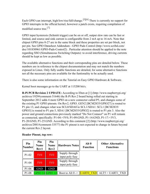
Header Pinout, top row:<br />
Pin<br />
Number<br />
Pin<br />
Name<br />
Rev1<br />
Pin<br />
Name<br />
Rev2<br />
P1-02 5V0 5V0<br />
P1-04 5V0 5V0<br />
P1-06 GND GND<br />
Hardware Notes<br />
Supply through<br />
input poly fuse<br />
Supply through<br />
input poly fuse<br />
Alt 0<br />
Function<br />
Other Alternative<br />
Functions<br />
P1-08 G<strong>PI</strong>O 14 G<strong>PI</strong>O 14 Boot to Alt 0 -> UART0_TXD ALT5 = UART1_TXD