POWEROHM - Revere Electric
POWEROHM - Revere Electric
POWEROHM - Revere Electric

Create successful ePaper yourself
Turn your PDF publications into a flip-book with our unique Google optimized e-Paper software.
PO Box 537 Katy, TX 77492<br />
Phone: (800) 838-4694<br />
Fax: (859)-384-8099<br />
Email: sales@powerohm.com<br />
Installation Instructions<br />
Construction: Powerohm braking resistors consists of smoothwound, wirewound or edgewound type<br />
resistor coils mounted in ventilated enclosures. All current carrying components used to manufacture our<br />
resistor coils including the elements and terminals are stainless steel for maximum corrosion resistance.<br />
Standard enclosures will be mill galvanized with terminals factory wired to a terminal block and normally<br />
closed thermal switch. Braking resistors are available with a variety of options such as special enclosure<br />
finishes and outdoor ratings.<br />
INSPECTION: Upon receipt of your Powerohm Braking Resistor, be sure to inspect the unit carefully for<br />
any shipping damage. After unpacking, check the unit for loose, broken, bent or otherwise damaged parts<br />
due to shipping. Report any shipping damage immediately to the freight carrier. Be sure to verify that the<br />
part number and ratings listed on the nameplate conform to the order specification. The ohm rating listed<br />
on the nameplate is critical (too low of an ohm value may cause damage to the drive).<br />
INSTALLATION:<br />
IMPORTANT: The National <strong>Electric</strong> Code (NEC) and local regulations govern the installation and<br />
wiring of electrical equipment such as braking resistors. DC power wiring, AC power wiring,<br />
control wiring and conduit must be installed in accordance with these codes.<br />
Powerohm braking assemblies cool by natural convection causing hot air to rise vertically from the<br />
enclosure. Braking resistors should be mounted in a well ventilated location free of any combustible<br />
materials or equipment affected by heat. Units should be installed with at least 24 inches of free space<br />
above the enclosure top and 6 inches of free space surrounding the enclosure sides. If necessary, units<br />
can be mounted on spacers or channels to limit heat from conducting from the resistor enclosure to its<br />
mounting surface.<br />
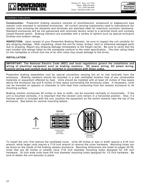
Braking resistor enclosures 28 inches or less in width, can be mounted vertically or horizontally. If the<br />
unit is mounted vertically, it is important that the resistor coils remain in a horizontal position. Also, if a<br />
thermal switch is included with the unit, position the equipment so the switch remains near the top of the<br />
enclosure. See below for vertical mounting details.<br />
TOP VIEW<br />
NORMALLY CLOSED<br />
THERMAL SWITCH<br />
(4) 7/16 DIA.<br />
AIR FLOW<br />
Correct Vertical<br />
Mounting<br />
(Front View)<br />
Incorrect Vertical<br />
Mounting<br />
(Front View)<br />
To install the unit, first remove the ventilated cover. Units 28 inches or less in width require a 5/16 inch<br />
wrench, while larger units require a 7/16 inch wrench to remove the cover hardware. Mounting holes can<br />
be found on the inside of the braking resistor enclosure. Mounting dimensions are listed on pages 25-36.<br />
Units that are 28 inches or smaller have 7/16 inch diameter mounting holes designed for 3/8 inch<br />
hardware. 30 inch wide units have 5/8 inch diameter mounting holes designed for 1/2 inch hardware. Be<br />
sure to fasten the unit securely in place.<br />
37