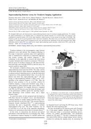
Superconducting Detector Array for Terahertz Imaging Applications
Superconducting Detector Array for Terahertz Imaging Applications
Superconducting Detector Array for Terahertz Imaging Applications

Create successful ePaper yourself
Turn your PDF publications into a flip-book with our unique Google optimized e-Paper software.
Jpn. J. Appl. Phys., Vol. 45, No. 37 (2006)<br />
S. ARIYOSHI et al.<br />
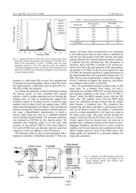
Table I.<br />
Spectral characteristics of the 0.65 THz band.<br />
<strong>Detector</strong> ID<br />
Peak frequency<br />
Bandwidth<br />
(GHz) (GHz) (%)<br />
ch.1 654 83 13<br />
ch.2 658 84 13<br />
ch.3 654 92 14<br />
ch.4 653 97 15<br />
ch.5 651 91 14<br />
Calculation 651 76 12<br />
Fig. 2. Spectral response of a linear array with five detector pixels. Each<br />
dotted line indicates measurement data normalized at 0.65 THz. Resolution<br />
of the spectrometer is 0.5 cm 1 (15 GHz), when the cosine<br />
apodization function is used. The solid line shows the numerical<br />
calculation of distributed junctions. A relatively wide bandwidth of more<br />
than 10% at 0.65 THz can be achieved by combining several narrow-band<br />
resonance frequency peaks.<br />
elements (i.e., 600 single STJs in total). We confirmed that<br />
45 elements showed good quality, which is about 90% yield.<br />
For single junctions, a fabrication yield of about 99% (i.e.,<br />
595 STJs in 600) was achieved.<br />
To evaluate the uni<strong>for</strong>mity of optical per<strong>for</strong>mance among<br />
the detector pixels, we have measured their spectral<br />
response, which is another important issue <strong>for</strong> realizing the<br />
imaging array. In order to simultaneously suppress DC<br />
Josephson current of all detector pixels, a relatively large<br />
magnetic field of about 30 mT was applied using a NbTi<br />
superconducting Helmholtz coil. Figure 2 shows the spectral<br />
response measured by Fourier trans<strong>for</strong>m infrared spectrometer<br />
using a Martin-Puplett interferometer, in which a<br />
mercury-vapor lamp was used as a wideband radiation<br />
source including terahertz bands. The maximum sensitivity<br />
was measured at 0.65 THz <strong>for</strong> five detector pixels. We<br />
confirmed their frequency peaks to be the same with<br />
accuracy of one percent (Table I). Two lower peaks at<br />
0.13 and 0.25 THz were also detected, when the same bias<br />
voltage of 1.0 mV was applied to each STJ detector.<br />
The frequency peaks are also in good agreement with a<br />
numerical calculation of distributed junctions. 14) This consistency<br />
will allow future developments to be constructed<br />
to the multi-spectral detector array, which is optimized by<br />
only the size and location of the STJs with the same plane<br />
antenna. However, the measured spectral response is partially<br />
different from the calculated one. The discrepancy in<br />
sensitivity above 0.65 THz is thought to be normal-conductor<br />
losses above the gap frequency of the superconducting<br />
niobium (0:7 THz). At the two lower peaks (0.13 and<br />
0.25 THz), the measured sensitivity is suppressed because of<br />
the limited bandwidth of the log-periodic antenna (0.3 –1.2<br />
THz). We have also confirmed that a smaller bias voltage of<br />
0.5 mV is sufficient to suppress the sensitivity, and realizes<br />
pure bandpass characteristics at 0.65 THz.<br />
Next, we demonstrated terahertz imaging using an STJ<br />
linear array. As a terahertz wave source, we used a<br />
backward-wave oscillator (BWO) <strong>for</strong> its high output power<br />
and frequency tunability in the range of 0.5 – 0.7 THz. 15)<br />
Figure 3 shows the BWO imaging system with the STJ<br />
linear array. The terahertz waves from the BWO point<br />
source are collimated and then focused onto the sample<br />
plane through a cylindrical lens. The cylindrical lens<br />
elongates the spot shape, and allows a good signal-to-noise<br />
ratio <strong>for</strong> all detector pixels. The sample is continuously<br />
moved in a plane perpendicular to the beam axis using an<br />
XY linear motor stage. The beam passing through the<br />
sample is refocused onto the STJ linear array in a cryostat.<br />
Current signals from the detector array are read out in<br />
parallel using a multipixel readout system based on transimpedance<br />
amplifiers, and then fed to a series of lock-in<br />
amplifiers one <strong>for</strong> each detector pixel synchronized with an<br />
optical chopper placed in front of the BWO source. The<br />
output signals are transfered to a personal computer <strong>for</strong><br />
image data acquisition.<br />
Fig. 3. Schematic of the BWO imaging system with<br />
the STJ-based linear array. The numbers on the<br />
optical elements indicate their effective focal<br />
lengths in millimeters.<br />
L1005<br />
-117-