R&S FSH Handheld Spectrum Analyzer - Rohde & Schwarz
R&S FSH Handheld Spectrum Analyzer - Rohde & Schwarz
R&S FSH Handheld Spectrum Analyzer - Rohde & Schwarz

Create successful ePaper yourself
Turn your PDF publications into a flip-book with our unique Google optimized e-Paper software.
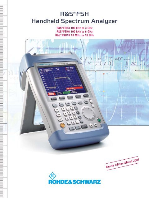
¸<strong>FSH</strong><br />
<strong>Handheld</strong> <strong>Spectrum</strong> <strong>Analyzer</strong><br />
¸<strong>FSH</strong>3 100 kHz to 3 GHz<br />
¸<strong>FSH</strong>6 100 kHz to 6 GHz<br />
¸<strong>FSH</strong>18 10 MHz to 18 GHz<br />
Fourth Edition March 2007
<strong>Spectrum</strong> analysis<br />
anywhere, anytime<br />
– on earth and in space<br />
The ¸<strong>FSH</strong> is the ideal spectrum analyzer for<br />
rapid, high-precision, cost-effective signal investigations.<br />
It provides a large number of measurement<br />
functions and so can handle anything from<br />
the installation or maintenance of a mobile radio<br />
base station up to on-site fault location in RF<br />
cables as well as development and service –<br />
an extensive range of applications.<br />
Due to its excellent characteristics,<br />
the ¸<strong>FSH</strong>3 is used on board the<br />
International Space Station (ISS) for<br />
distance-to-fault measurements on RF<br />
antenna cables.<br />
2<br />
¸<strong>FSH</strong> <strong>Handheld</strong> <strong>Spectrum</strong> <strong>Analyzer</strong>
Handy, robust, and<br />
portable<br />
Trace<br />
Memory Trace<br />
Clear/Write<br />
Max/Min Hold<br />
Average<br />
View<br />
Detectors<br />
– Auto Peak<br />
– Sample<br />
– Max/Min Peak<br />
– RMS<br />
The ¸<strong>FSH</strong> has been designed as a robust,<br />
portable spectrum analyzer that can be used in<br />
the field.<br />
Function keys<br />
Softkey function<br />
Robust edge protection,<br />
stable carrying handle<br />
Easy operation<br />
Four hours operating time on battery power<br />
Storage of up to 256 traces and setups<br />
Easy data transfer to PC<br />
High measurement accuracy<br />
Best RF characteristics in its class<br />
The ¸<strong>FSH</strong> can, of course, also be used on<br />
the lab bench. The ¸<strong>FSH</strong> has an adjustable,<br />
fold-out stand to position the instrument to an<br />
optimal display viewing angle.<br />
The ¸<strong>FSH</strong> and its accessories can be stored and<br />
transported in the compact and sturdy aluminum transit<br />
case.<br />
<strong>Handheld</strong> <strong>Spectrum</strong> <strong>Analyzer</strong> ¸<strong>FSH</strong><br />
12
Selection of measurement<br />
functions:<br />
<strong>Spectrum</strong> analysis<br />
Scalar network analysis<br />
Vector network analysis<br />
Receiver mode<br />
Channel power<br />
TDMA power<br />
Occupied bandwidth<br />
DTF<br />
3GPP code domain power<br />
Isotropic antenna<br />
C/N measurement<br />
Power<br />
Transducer factors<br />
Limit lines<br />
Display line<br />
Selection of following functions:<br />
Marker<br />
Delta marker<br />
Noise marker<br />
Frequency counter<br />
Multimarker<br />
Memory for up to 256 traces<br />
and setups<br />
Direct printout of measurement<br />
results<br />
Transflective color display with<br />
320 × 240 pixel, switchable to<br />
monochrome display for highcontrast<br />
display when used in<br />
direct sunlight in the field<br />
RS-232-C optical interface<br />
Simple menu-based operation<br />
via softkeys<br />
General instrument setups<br />
Current instrument setting<br />
Rotary knob<br />
Default setting<br />
Cursor keys<br />
¸<strong>FSH</strong> <strong>Handheld</strong> <strong>Spectrum</strong> <strong>Analyzer</strong><br />
3
AC power supply connector<br />
Generator output, N connector<br />
Power sensor connector<br />
Trigger input/<br />
external reference input<br />
RF input, N connector<br />
Data in brief<br />
Headphones connector<br />
¸<strong>FSH</strong>3 ¸<strong>FSH</strong>6 ¸<strong>FSH</strong>18<br />
Frequency range 100 kHz to 3 GHz 100 kHz to 6 GHz 10 MHz to 18 GHz<br />
Resolution bandwidths 1 kHz to 1 MHz (model .13)<br />
100 Hz to 1 MHz (models .03 and .23)<br />
Video bandwidths<br />
10 Hz to 1 MHz<br />
Displayed average noise level typ. –114 dBm (1 kHz) (model .13)<br />
typ. –135 dBm (100 Hz) (models .03 and .23)<br />
100 Hz to 1 MHz<br />
typ. –135 dBm (100 Hz)<br />
typ. –128 dBm (100 Hz)<br />
TOI typ. 13 dBm typ. 7 dBm<br />
SSB phase noise
¸<strong>FSH</strong> – options and applications<br />
The ¸<strong>FSH</strong> can be used for measurements up to an upper frequency limit of 3 GHz, 6 GHz, and<br />
18 GHz. The 3 GHz and 6 GHz are available with or without internal tracking generator. When the tracking<br />
generator is included, the ¸<strong>FSH</strong> can be used for distance-to-fault (DTF) measurements, scalar<br />
and vector network analysis, and one-port cable loss measurement. Almost all models come standard<br />
with an adjustable preamplifier, making them suitable for measuring very small signals. Power sensors<br />
are available as accessories for high-precision terminating power measurements up to 8 GHz or<br />
18 GHz as well as for directional power measurements up to 4 GHz. The following tables show possible<br />
configurations for various applications and an overview of available models.<br />
Product<br />
¸<strong>FSH</strong> (models .03/.06)<br />
with preamplifier<br />
Application<br />
<br />
TDMA power measurements<br />
<br />
Channel-power measurements<br />
Field-strength measurements/<br />
measurements with isotropic antenna<br />
C/N measurements<br />
<br />
<br />
Channel tables<br />
+¸<br />
–<br />
<strong>FSH</strong>-K3<br />
Receiver mode<br />
Code domain power measurements<br />
on 3GPP base stations 1)<br />
+¸<br />
<strong>FSH</strong>-Z1/<br />
-Z18<br />
Power measurements up to 8 GHz/18 GHz<br />
Measurements on cables (distance-to-fault)<br />
Directional power measurements up to 1 GHz/4 GHz<br />
+¸<br />
<strong>FSH</strong>-Z14/<br />
-Z44<br />
Scalar transmission measurements<br />
Vector transmission measurements 2)<br />
Scalar reflection measurements<br />
Vector reflection measurements 2)<br />
Remote control via RS-232-C<br />
interface<br />
One-port cable loss<br />
measurements<br />
+¸<br />
– – – <strong>FSH</strong>-K1 –<br />
¸<strong>FSH</strong> (model .13)<br />
with tracking generator<br />
<br />
<br />
<br />
<br />
<br />
+¸<br />
<strong>FSH</strong>-K3<br />
–<br />
+¸<br />
<strong>FSH</strong>-Z1/<br />
-Z18<br />
+¸<br />
<strong>FSH</strong>-Z14/<br />
-Z44<br />
+¸<br />
<strong>FSH</strong>-Z2/Z3<br />
+¸<br />
<strong>FSH</strong>-B1<br />
<br />
+¸<br />
<strong>FSH</strong>-Z2<br />
+¸<br />
<strong>FSH</strong>-K1<br />
+¸<br />
<strong>FSH</strong>-Z2/Z3<br />
+¸<br />
<strong>FSH</strong>-K2<br />
¸<strong>FSH</strong> (models .23/.26)<br />
with tracking generator and<br />
preamplifier<br />
<br />
<br />
<br />
+¸<br />
<strong>FSH</strong>-K3<br />
+¸<br />
<strong>FSH</strong>-K4<br />
+¸<br />
<strong>FSH</strong>-Z1/<br />
-Z18<br />
+¸<br />
<strong>FSH</strong>-Z14/<br />
-Z44<br />
+¸<br />
<strong>FSH</strong>-Z2/Z3<br />
+¸<br />
<strong>FSH</strong>-B1<br />
<br />
+¸<br />
<strong>FSH</strong>-Z2/Z3<br />
+¸<br />
<strong>FSH</strong>-K1<br />
+¸<br />
<strong>FSH</strong>-Z2/Z3<br />
+¸<br />
<strong>FSH</strong>-K2<br />
¸<strong>FSH</strong>18<br />
<br />
+¸<br />
+¸ +¸<br />
+¸<br />
<strong>FSH</strong>-K3<br />
– <strong>FSH</strong>-Z1/ <strong>FSH</strong>-Z14/ –<br />
<strong>FSH</strong>-K1<br />
-Z18<br />
– – –<br />
-Z44<br />
1 )<br />
For ¸<strong>FSH</strong> 3 model .23 with serial no. 103500 ¸<strong>FSH</strong> standard function<br />
or later.<br />
2) – Not available<br />
¸<strong>FSH</strong>-K2 required.<br />
¸<strong>FSH</strong> – models<br />
Frequency range Tracking generator Output power of<br />
tracking generator<br />
Preamplifier<br />
Resolution bandwidth<br />
¸<strong>FSH</strong>3 model .03 100 kHz to 3 GHz – – 100 Hz to 1 MHz<br />
¸<strong>FSH</strong>3 model .13 100 kHz to 3 GHz –20 dBm – 1 kHz to 1 MHz<br />
¸<strong>FSH</strong>3 model .23 100 kHz to 3 GHz –20 dBm/0 dBm, selectable 100 Hz to 1 MHz<br />
¸<strong>FSH</strong>6 model .06 100 kHz to 6 GHz – – 100 Hz to 1 MHz<br />
¸<strong>FSH</strong>6 model .26 100 kHz to 6 GHz –10 dBm (f < 3 GHz)<br />
–20 dBm (f > 3 GHz)<br />
<br />
100 Hz to 1 MHz<br />
¸<strong>FSH</strong>18 10 MHz to 18 GHz – – – 100 Hz to 1 MHz<br />
<br />
¸<strong>FSH</strong> <strong>Handheld</strong> <strong>Spectrum</strong> <strong>Analyzer</strong>
TDMA power measurements<br />
By means of the TDMA POWER function, the ¸<strong>FSH</strong> performs time-domain<br />
power measurements within a timeslot of TDMA (time division multiple access)<br />
methods. All the settings required for the GSM and EDGE standards are<br />
predefined on the ¸<strong>FSH</strong> to make these measurements easier for the user.<br />
In addition, up to five user-definable instrument setups can be loaded into the<br />
¸<strong>FSH</strong> using the ¸<strong>FSH</strong> View software.<br />
Channel-power measurements<br />
The ¸<strong>FSH</strong> determines the power of a definable transmission channel<br />
by means of the channel-power measurement function. A channel-power<br />
measurement for the digital mobile radio standards 3GPP WCDMA, cdmaOne,<br />
and CDMA2000® 1x is performed at a keystroke with all the correct instrument<br />
settings. With the ¸<strong>FSH</strong>View software, the user can quickly and easily<br />
define further standards and load them into the ¸<strong>FSH</strong>.<br />
CDMA2000® is a registered trademark of the Telecommunications Industry Association (TIA USA)<br />
Field-strength measurements<br />
When measuring electric field strength, the ¸<strong>FSH</strong> takes into account the<br />
specific antenna factors of the connected antenna. Field strength is displayed<br />
directly in dBµV/m. If W/m 2 is selected, the power flux density is calculated<br />
and displayed. In addition, frequency-dependent loss or gain of, for<br />
example, a cable or an amplifier can be corrected. For quick and easy result<br />
analysis, the ¸<strong>FSH</strong> provides two user-definable limit lines with automatic<br />
limit monitoring.<br />
¸<strong>FSH</strong> with ¸HE 200 active directional antenna (optional accessory)<br />
Field-strength measurements with isotropic<br />
antenna<br />
When used with the ¸TS-EMF isotropic antenna, the ¸<strong>FSH</strong> can<br />
determine the direction-independent resultant field strength in the frequency<br />
range from 30 MHz to 3 GHz. For measuring the resultant field strength, the<br />
antenna has three orthogonal antenna elements. The ¸<strong>FSH</strong> successively<br />
triggers the three antenna elements and calculates the resultant field strength.<br />
The calculation takes into account the antenna factors for each individual<br />
antenna element as well as the cable loss of the connecting cable.<br />
¸<strong>FSH</strong> with ¸TS-EMF isotropic antenna (optional accessory)<br />
¸<strong>FSH</strong> <strong>Handheld</strong> <strong>Spectrum</strong> <strong>Analyzer</strong>
C/N measurements<br />
The ¸<strong>FSH</strong> offers a carrier/noise (C/N) measurement for determining the<br />
ratio of carrier power to noise power or carrier power to noise power density.<br />
The ¸<strong>FSH</strong> supports three different modes for carrier power measurement.<br />
In the CW TX mode, the ¸<strong>FSH</strong> determines the power of an unmodulated<br />
carrier. In the digital TX mode, it determines the channel power of a reference<br />
channel, as is common with digitally modulated carriers (e.g. the DAB, DVB,<br />
DVB-T, DVB-H, and J.83/A/B/C standards). Furthermore, the ATSC standard for<br />
digital terrestrial television with 8VSB modulation is supported. In the analog<br />
TV mode, the ¸<strong>FSH</strong> measures the peak power of the vision carrier with<br />
amplitude-modulated TV signals.<br />
Channel tables<br />
If preferred, the ¸<strong>FSH</strong> can be tuned by channel numbers rather than by<br />
entering the frequency. The channel number is displayed instead of the center<br />
frequency. Users who are accustomed to channel assignments, which are<br />
common in TV and mobile radio applications, can operate the ¸<strong>FSH</strong> more<br />
easily. The channel tables are generated with the ¸<strong>FSH</strong>View software<br />
and loaded into the ¸<strong>FSH</strong>. The ¸<strong>FSH</strong> includes TV channel tables for a<br />
number of countries<br />
Receiver mode<br />
When equipped with the ¸<strong>FSH</strong>-K3 option, the ¸<strong>FSH</strong> can be operated<br />
as a receiver for monitoring and precompliance EMC applications. Measurements<br />
are performed at a predefined frequency with a user-selectable measurement<br />
time. In the scan mode, the ¸<strong>FSH</strong> sequentially measures each level<br />
at various frequencies defined in a channel table. The channel tables are<br />
generated with the ¸<strong>FSH</strong>View software and loaded into the ¸<strong>FSH</strong>. For<br />
a few TV transmitter and mobile radio standards, the tables are predefined.<br />
In addition, the CISPR bandwidths 200 Hz, 9 kHz, 120 kHz, and 1 MHz are<br />
available for EMI emission measurements. The ¸<strong>FSH</strong> offers peak, average,<br />
RMS, and quasi-peak detectors.<br />
<br />
¸<strong>FSH</strong> <strong>Handheld</strong> <strong>Spectrum</strong> <strong>Analyzer</strong>
Power measurements<br />
The ¸<strong>FSH</strong>-Z1 and ¸<strong>FSH</strong>-Z18 power sensors expand the ¸<strong>FSH</strong> to a<br />
high-precision RF power meter up to 8 GHz and 18 GHz respectively. As with<br />
thermal sensors, the true RMS value of the measured signal is obtained over<br />
the entire measurement range of –67 dBm to +23 dBm irrespective of the<br />
signal waveform. In particular with modulated signals, additional measurement<br />
errors can thus be prevented, and handling becomes easy.<br />
Directional power measurements<br />
The ¸<strong>FSH</strong>-Z14 and ¸<strong>FSH</strong>-Z44 directional power sensors turn the<br />
¸<strong>FSH</strong> into a full-fledged directional power meter with a frequency range of<br />
25 MHz to 1 GHz and 200 MHz to 4 GHz. The ¸<strong>FSH</strong> can then simultaneously<br />
measure the output power and the matching of transmitter system antennas<br />
under operating conditions. The power sensors measure average power up<br />
to 120 W and normally eliminate the need for any extra attenuators. They are<br />
compatible with the common standards GSM/EDGE, 3GPP WCDMA, cdmaOne,<br />
CDMA2000® 1x, DVB-T, and DAB. Additionally, the peak envelope power (PEP)<br />
can be determined up to a maximum of 300 W.<br />
¸<strong>FSH</strong> with<br />
¸<strong>FSH</strong>-Z44 directional<br />
power sensor<br />
Measurements on cables (distance to fault)<br />
The ¸<strong>FSH</strong>-B1 option allows the distance to any faults in an RF cable to be<br />
determined rapidly and accurately. Distance-to-fault measurements using the<br />
¸<strong>FSH</strong>-Z2/-Z3 VSWR bridge provide an immediate overview of the state of<br />
the device under test (return loss and distance, see figure). The marker-zoom<br />
function allows detailed analysis of faults with a resolution of up to 1024 pixel.<br />
Only applies to the ¸<strong>FSH</strong> with tracking generator and ¸<strong>FSH</strong>-B1<br />
(distance-to-fault measurement) and ¸<strong>FSH</strong>-Z2/-Z3 (VSWR bridge) options installed<br />
¸<strong>FSH</strong> <strong>Handheld</strong> <strong>Spectrum</strong> <strong>Analyzer</strong>
Scalar transmission and reflection measurements<br />
with VSWR bridge<br />
The ¸<strong>FSH</strong> with built-in tracking generator rapidly determines the<br />
transmission characteristics of cables, filters, amplifiers, etc, with a<br />
minimum of effort. When equipped with the ¸<strong>FSH</strong>-Z2/-Z3 VSWR bridge<br />
(10 MHz to 3 GHz/6 GHz), the ¸<strong>FSH</strong> can also measure the matching (return loss,<br />
reflection coefficient, or VSWR) of an antenna, for example. The bridge is screwconnected<br />
directly to the ¸<strong>FSH</strong>’s RF input and tracking generator output<br />
without involving cumbersome, extra cabling. The innovative design of the<br />
¸<strong>FSH</strong>-Z3 VSWR bridge with integrated RF bypass switch allows the user<br />
to make spectrum and transmission measurements also with the bridge<br />
connected. Active components such as amplifiers can be supplied directly via<br />
the RF cable by means of the two integrated bias tees.<br />
¸<strong>FSH</strong>-Z3 VSWR bridge<br />
Measurement of<br />
magnitude and phase in<br />
Smith chart<br />
Measurement of<br />
phase<br />
Vector transmission and reflection measurements<br />
Compared to scalar transmission and reflection measurements, the ¸<strong>FSH</strong>-<br />
K2 option offers a significant increase in measurement accuracy and number<br />
of measurement functions. In addition to the magnitude of S11 and S21, the<br />
phase, group delay, and electrical length of a DUT can be determined. The<br />
Smith chart allows simultaneous display of magnitude and phase in order to<br />
analyze the matching of an antenna in detail, for example. A user-definable<br />
limit line and a zoom function come in handy when evaluating the measurement<br />
results. Owing to a wide variety of marker formats, the measured values<br />
are displayed in virtually all the conventional formats used in network analysis.<br />
The input of a reference impedance permits measurements on DUTs whose<br />
impedance is not 50 Ω. To increase measurement accuracy, the ¸<strong>FSH</strong><br />
performs complex correction of the system errors after calibration.<br />
One-port cable loss measurements<br />
The ¸<strong>FSH</strong> with tracking generator and VSWR bridge can determine the<br />
cable loss of previously installed long cables without much effort. One end of<br />
the cable is connected to the VSWR bridge, and the other end is terminated<br />
with a short circuit or simply left open. The calculated cable loss represents<br />
the average value within the displayed frequency range. The loss at specific<br />
frequencies is determined via markers. The one-port cable loss measurement is<br />
only available with the ¸<strong>FSH</strong>-K2 option.<br />
<br />
¸<strong>FSH</strong> <strong>Handheld</strong> <strong>Spectrum</strong> <strong>Analyzer</strong>
3GPP FDD code domain power measurements<br />
on base stations<br />
The ¸<strong>FSH</strong>-K4 option 1) allows code domain power measurements on a<br />
3GPP base station. It measures the total power and the power of the most<br />
important code channels, such as the common pilot channel (CPICH), primary<br />
common control physical channel (P-CCPCH), primary synchronization channel<br />
(P-SCH), and secondary synchronization channel (S-SCH). Furthermore, the<br />
carrier frequency offset and the error vector magnitude (EVM) are measured<br />
and displayed. The scrambling code can be determined at the press of a button<br />
and used automatically for decoding the code channels. The user can also<br />
get a quick overview of adjacent base stations. The ¸<strong>FSH</strong> can display up<br />
to eight scrambling codes with their CPICH power. The ¸<strong>FSH</strong>-K4 option<br />
provides automatic level setting for fast and optimal setting of the reference<br />
level. In practice, this means very easy operation. To display the code domain<br />
power measurement values, only four operating steps are necessary:<br />
1)<br />
Available for the ¸<strong>FSH</strong>3 (model .23) with serial number 103500 or<br />
later.<br />
<br />
<br />
<br />
<br />
Select the 3GPP CDP function<br />
Set the center frequency<br />
Use “Level Adjust“ to optimize the level setting<br />
Start the scrambling code search<br />
For base stations with two antennas, the user can select which antenna the<br />
¸<strong>FSH</strong> should synchronize to (antenna diversity).<br />
Locating EMC weak spots<br />
The ¸HZ-15 near-field probe set is a diagnostic tool for locating EMC<br />
weak spots on printed boards, integrated circuits, cables, shieldings, and<br />
other trouble spots. The ¸HZ-15 near-field probe set can handle emission<br />
measurements from 30 MHz to 3 GHz. Its sensitivity can be enhanced by adding<br />
the ¸HZ-16 preamplifier, which has a frequency range of up to 3 GHz, a<br />
gain of approx. 20 dB, and a noise figure of 4.5 dB. In combination with the<br />
¸<strong>FSH</strong>, the preamplifier and near-field probe set are a cost-effective means<br />
of analyzing and locating sources of interference during development.<br />
¸<strong>FSH</strong> with near-field probe set and DUT<br />
¸<strong>FSH</strong> <strong>Handheld</strong> <strong>Spectrum</strong> <strong>Analyzer</strong>
¸<strong>FSH</strong> View Control Software<br />
The powerful software package for documenting your measurements is<br />
supplied with every ¸<strong>FSH</strong>.<br />
Features<br />
<br />
Runs under Windows 98/ME/NT/2000/XP<br />
<br />
Automatic storage of measurement results at selectable<br />
<br />
Rapid and simple transfer of measurement data from the<br />
intervals<br />
¸<strong>FSH</strong> to a PC and vice versa<br />
<br />
Generation of cable data with a built-in cable editor;<br />
<br />
Data export in ASCII or MS Excel format<br />
downloading to the ¸<strong>FSH</strong> for distance-to-fault mea-<br />
<br />
Printout of all relevant data via Windows<br />
surements (¸<strong>FSH</strong>-B1)<br />
(screenshot of the ¸<strong>FSH</strong> display for documentation)<br />
<br />
Editor for generating limit lines, user-definable standards<br />
<br />
Graphics data stored in standard formats<br />
(measurement of occupied bandwidth, channel power,<br />
(.bmp, .pcx, .png, .wmf)<br />
and TDMA power), transducer factors, and correction fac-<br />
<br />
Permanent and continuous transfer of sweeps to the PC;<br />
tors for taking into account external attenuators or ampli-<br />
facilities for subsequent analysis (markers, zoom, etc)<br />
fiers, as well as channel lists<br />
<br />
Storage space for traces and measurement data, as well as<br />
<br />
Macro function for Word for fast and easy documentation<br />
for comparisons of current and previous measurements (avail-<br />
of measurement results<br />
able space is limited only by the size of the hard disk<br />
<br />
Connection between PC and ¸<strong>FSH</strong> via interference-<br />
of the controlling PC)<br />
free, RS-232-C optical interface<br />
10<br />
¸<strong>FSH</strong> <strong>Handheld</strong> <strong>Spectrum</strong> <strong>Analyzer</strong>
Specifications<br />
Specifications apply under the following conditions: 15 minutes warm-up time at ambient temperature, specified<br />
environmental conditions met, and calibration cycle adhered to. Data without tolerances: typical values.<br />
Data designated as “nominal”: design parameters, i. e. not tested.<br />
Frequency<br />
¸<strong>FSH</strong>3 ¸<strong>FSH</strong>6 ¸<strong>FSH</strong>18<br />
Frequency range 100 kHz to 3 GHz 100 kHz to 6 GHz 10 MHz to 18 GHz<br />
Reference frequency<br />
Aging<br />
Temperature drift 0 °C to +30 °C<br />
+30 °C to +50 °C<br />
Frequency counter<br />
Resolution<br />
1 ppm/year<br />
2 ppm<br />
in addition 2 ppm/10 °C<br />
1 Hz<br />
Counter accuracy S/N > 25 dB ± (frequency × reference frequency error)<br />
Frequency span model .03/.23,<br />
model .06/.26<br />
model .13<br />
model .18<br />
Spectral purity<br />
0 Hz, 100 Hz to 3 GHz<br />
–<br />
0 Hz, 1 kHz to 3 GHz<br />
–<br />
–<br />
0 Hz, 100 Hz to 6 GHz<br />
–<br />
–<br />
–<br />
–<br />
–<br />
0 Hz, 100 Hz to 18 GHz<br />
SSB phase noise<br />
f = 500 MHz,<br />
+20 °C to +30 °C<br />
30 kHz from carrier
Amplitude<br />
Display range<br />
¸<strong>FSH</strong>3 ¸<strong>FSH</strong>6 ¸<strong>FSH</strong>18<br />
average noise level displayed to +20 dBm<br />
Maximum permissible DC voltage at RF input 50 V/80 V 1) 50 V<br />
Maximum power 20 dBm, 30 dBm (1 W) for max. 3 minutes 20 dBm<br />
Intermodulation-free dynamic range third-order IM products,<br />
2 × –20 dBm, reference<br />
level = –10 dBm<br />
at signal offset ≤2 MHz<br />
at signal offset >2 MHz<br />
typ. 66 dB (typ. +13 dBm third-order intercept, TOI)<br />
60 dB (nominal, +10 dBm TOI)<br />
66 dB (nominal, typ. +13 dBm TOI)<br />
Displayed average noise level<br />
10 MHz to 50 MHz<br />
50 MHz to 3 GHz<br />
3 GHz to 5 GHz<br />
5 GHz to 6 GHz<br />
6 GHz to 8 GHz<br />
8 GHz to 12 GHz<br />
12 GHz to 16 GHz<br />
16 GHz to 18 GHz<br />
With preamplifier<br />
10 MHz to 2.5 GHz<br />
2.5 GHz to 3 GHz<br />
3 GHz to 5 GHz<br />
5 GHz to 6 GHz<br />
Inherent spurious<br />
Input related spurious<br />
Up to 3 GHz<br />
3 GHz to 6 GHz<br />
Receive frequency =<br />
signal frequency –2.0156 GHz<br />
Input related spurious<br />
10 MHz to 14 GHz<br />
14 GHz to 18 GHz<br />
Receive frequency =<br />
signal frequency – 3.9 GHz<br />
signal frequency + 0.6 GHz to + 1 GHz<br />
signal frequency – 0.6 GHz to – 1 GHz<br />
2nd harmonic, receive frequency:<br />
Up to 6 GHz<br />
6 GHz to 9 GHz<br />
Level display<br />
Reference level<br />
Display range<br />
Display units<br />
Logarithmic<br />
Linear<br />
Traces<br />
Trace mathematics<br />
Detectors<br />
resolution bandwidth<br />
1 kHz,<br />
video bandwidth 10 Hz,<br />
reference level ≤–30 dBm<br />
only models .03 2) , .23, .06<br />
and .26<br />
reference level<br />
≤–20 dBm, f > 30 MHz,<br />
RBW ≤ 100 kHz<br />
¸<strong>FSH</strong>3/6:<br />
mixer level ≤–40 dBm,<br />
carrier offset >1 MHz<br />
for signal frequencies<br />
2 GHz to 3.2 GHz<br />
¸<strong>FSH</strong>18:<br />
mixer level ≤–20 dBm<br />
carrier offset >1 MHz<br />
10 MHz to 7.6 GHz<br />
7.6 GHz to 18 GHz<br />
10 MHz to 2.8 GHz<br />
2.8 GHz to 7.6 GHz<br />
7.6 GHz to 18 GHz<br />
for signal frequencies<br />
3.9 GHz to 18 GHz<br />
7.4 GHz to 7.7 GHz<br />
7.8 GHz to 8.5 GHz<br />
mixer level –40 dBm<br />
with option ¸<strong>FSH</strong>-K3<br />
installed<br />
Level measurement error reference level to reference level –50 dB, +20 °C to +30 °C<br />
Markers<br />
Number of markers or delta markers max. 6<br />
Marker functions<br />
Marker displays<br />
Trigger<br />
Audio demodulation<br />
Inputs<br />
RF input<br />
Input impedance<br />
VSWR<br />
Trigger/external reference input<br />
Trigger voltage<br />
Reference frequency<br />
¸<strong>FSH</strong>3 ¸<strong>FSH</strong>6 ¸<strong>FSH</strong>18<br />
1 MHz to 10 MHz
Accessories<br />
¸<strong>FSH</strong>-Z1 and ¸<strong>FSH</strong>-Z18 power sensors<br />
¸<strong>FSH</strong>3 ¸<strong>FSH</strong>6 ¸<strong>FSH</strong>18<br />
Frequency range<br />
¸<strong>FSH</strong>-Z1<br />
¸<strong>FSH</strong>-Z18<br />
VSWR<br />
10 MHz to 30 MHz<br />
30 MHz to 2.4 GHz<br />
2.4 GHz to 8 GHz<br />
8 GHz to 18 GHz<br />
Maximum input power<br />
Measurement range<br />
Signal weighting<br />
Effect of harmonics<br />
Effect of modulation<br />
Absolute measurement uncertainty<br />
10 MHz to 8 GHz<br />
8 GHz to 18 GHz<br />
Zero offset after zeroing<br />
Dimensions (W × H × D)<br />
Weight<br />
¸<strong>FSH</strong>-Z14 directional power sensor<br />
Frequency range<br />
Power measurement range<br />
average power<br />
peak power<br />
(
Temperature coefficient<br />
25 MHz to 40 MHz<br />
40 MHz to 1 GHz<br />
Peak envelope power<br />
¸<strong>FSH</strong>3 ¸<strong>FSH</strong>6 ¸<strong>FSH</strong>18<br />
0.40 %/K (0.017 dB/K)<br />
0.25 %/K (0.011 dB/K)<br />
Power measurement range for video<br />
bandwidth<br />
4 kHz<br />
200 kHz<br />
600 kHz<br />
0.4 W to 300 W<br />
1 W to 300 W<br />
2 W to 300 W<br />
Measurement uncertainty +18 °C to +28 °C same as for average power, plus effect of peak hold circuit<br />
Accuracy of peak hold circuit for burst<br />
signals<br />
Duty cycle ≤ 0.1 and<br />
repetition rate ≥ 100/s<br />
20/s ≤ repetition rate < 100/s<br />
0.001 ≤ duty cycle < 0.1<br />
Temperature coefficient<br />
25 MHz to 40 MHz<br />
40 MHz to 1 GHz<br />
Load matching<br />
video bandwidth<br />
4 kHz<br />
200 kHz<br />
600 kHz<br />
±(3 % of measured value + 0.05 W) at burst width > 200 µs<br />
±(3 % of measured value + 0.20 W) at burst width > 4 µs<br />
±(7 % of measured value + 0.40 W) at burst width > 2 µs<br />
in addition ±(1.6 % of measured value + 0.15 W)<br />
in addition ±0.10 W<br />
0.50 %/K (0.022 dB/K)<br />
0.35 %/K (0.015 dB/K)<br />
Matching measurement range<br />
Return loss<br />
VSWR<br />
0 dB to 23 dB<br />
>1.15<br />
Minimum forward power specs met at ≥ 0.4 W 0.06 W<br />
Power-handling capacity<br />
Limits of measurement uncertainty for matching measurements<br />
Dimensions (W × H × D)<br />
Weight<br />
120 mm × 95 mm × 39 mm (4.72 in × 3.74 in × 1.53 in)<br />
connecting cable 1.5 m (59.05 in)<br />
0.65 kg (1.43 lb)<br />
¸<strong>FSH</strong> <strong>Handheld</strong> <strong>Spectrum</strong> <strong>Analyzer</strong><br />
15
¸<strong>FSH</strong>‐Z44 directional power sensor<br />
Frequency range<br />
Power measurement range<br />
VSWR referenced to 50 Ω<br />
200 MHz to 3 GHz<br />
3 GHz to 4 GHz<br />
Power-handling capacity<br />
Insertion loss<br />
200 MHz to 1.5 GHz<br />
1.5 GHz to 4 GHz<br />
Directivity<br />
200 MHz to 3 GHz<br />
3 GHz to 4 GHz<br />
Signal weighting<br />
depending on temperature<br />
and matching<br />
(see diagram on page 17)<br />
¸<strong>FSH</strong>3 ¸<strong>FSH</strong>6 ¸<strong>FSH</strong>18<br />
200 MHz to 4 GHz<br />
30 mW to 120 W (300 W with unmodulated envelope)<br />
Load matching<br />
¸<strong>FSH</strong>3 ¸<strong>FSH</strong>6 ¸<strong>FSH</strong>18<br />
Return loss<br />
200 MHz to 3 GHz<br />
3 GHz to 4 GHz<br />
VSWR<br />
200 MHz to 3 GHz<br />
3 GHz to 4 GHz<br />
0 dB to 23 dB<br />
0 dB to 20 dB<br />
>1.15<br />
>1.22<br />
Minimum forward power specs met ≥ 0.2 W 0.03 W<br />
Forward power<br />
1000<br />
800<br />
600<br />
400<br />
200<br />
AVG –10°C to +35°C<br />
VSWR ≤ 3<br />
AVG +35°C to +50°C<br />
VSWR ≤ 3<br />
PEAK (max. 10 ms), VSWR ≤ 3<br />
AVG –10°C to +35°C<br />
VSWR ≤ 1.5<br />
Measurement error<br />
6<br />
dB<br />
4<br />
2<br />
0<br />
–2<br />
0.2 GHz to 3 GHz<br />
3 GHz to 4 GHz<br />
100<br />
0.2 0.4 0.7 1 23 4 GHz<br />
–4<br />
0 5 10 15 20 dB 25<br />
Return loss<br />
Power-handling capacity<br />
Frequency<br />
Limits of measurement uncertainty for matching measurements<br />
Dimensions (W × H × D)<br />
Weight<br />
120 mm × 95 mm × 39 mm (4.72 in × 3.74 in × 1.53 in)<br />
connecting cable 1.5 m (59.05 in)<br />
0.65 kg (1.43 lb)<br />
¸<strong>FSH</strong> <strong>Handheld</strong> <strong>Spectrum</strong> <strong>Analyzer</strong><br />
17
¸<strong>FSH</strong>-Z2/¸<strong>FSH</strong>-Z3 VSWR bridge<br />
¸<strong>FSH</strong>-Z2<br />
¸<strong>FSH</strong>-Z3<br />
Frequency range 10 MHz to 3 GHz 10 MHz to 6 GHz<br />
Impedance<br />
VSWR bridge<br />
Directivity<br />
10 MHz to 30 MHz<br />
30 MHz to 1 GHz<br />
1 GHz to 3 GHz<br />
3 GHz to 6 GHz<br />
Directivity, corrected<br />
2 MHz to 10 MHz<br />
10 MHz to 3 GHz<br />
3 GHz to 6 GHz<br />
Return loss at test port<br />
10 MHz to 50 MHz<br />
50 MHz to 3 GHz<br />
3 GHz to 6 GHz<br />
Return loss at test port, corrected<br />
2 MHz to 3 GHz<br />
3 GHz to 6 GHz<br />
Insertion loss<br />
Test port<br />
Bypass<br />
DC bias<br />
¸<strong>FSH</strong>-K2 option<br />
¸<strong>FSH</strong>-K2 option<br />
50 Ω<br />
typ. 30 dB<br />
typ. 30 dB<br />
typ. 25 dB<br />
–<br />
typ. 40 dB<br />
typ. 43 dB<br />
–<br />
typ. 20 dB<br />
typ. 20 dB<br />
–<br />
typ. 35 dB<br />
–<br />
typ. 9 dB<br />
–<br />
typ. 16 dB<br />
>20 dB, typ. 28 dB<br />
>20 dB, typ. 28 dB<br />
>16 dB, typ. 25 dB<br />
typ. 40 dB<br />
typ. 40 dB<br />
typ. 37 dB<br />
>12 dB, typ. 18 dB<br />
>16 dB, typ. 22 dB<br />
>16 dB, typ. 22 dB<br />
typ. 40 dB<br />
typ. 37 dB<br />
typ. 9 dB<br />
typ. 4 dB<br />
Max. input voltage – 50 V<br />
Max. input current – 300 mA, 600 mA 6)<br />
Type of connector – BNC female<br />
Connectors<br />
Generator input/RF output<br />
Test port<br />
Control interface<br />
N male<br />
N female<br />
7-contact connector (type Binder)<br />
Calibration standards ¸<strong>FSH</strong>-Z29/-Z30/-Z31 ¸<strong>FSH</strong>-Z28<br />
Short/open<br />
N male<br />
50 Ω load N male<br />
Impedance<br />
Return loss<br />
DC to 3 GHz<br />
3 GHz to 6 GHz<br />
50 Ω<br />
>43 dB<br />
–<br />
Power-handling capacity 1 W 1 W<br />
General data<br />
>40 dB, typ. 46 dB<br />
>37 dB, typ. 43 dB<br />
Power consumption – 3 mW (nominal)<br />
Dimensions (W × H × D)<br />
169 mm × 116 mm × 30 mm<br />
6.65 in × 4.57 in × 1.18 in<br />
149 mm × 144 mm × 45 mm<br />
5.87 in × 5.67 in × 1.77 in<br />
Weight 485 g (1.07 lb) 620 g (1.37 lb)<br />
Distance-to-fault measurement<br />
Display<br />
¸<strong>FSH</strong>-B1 option only with ¸<strong>FSH</strong> models .13/.23/.26 and ¸<strong>FSH</strong>-Z2/-Z3 VSWR bridges<br />
301 pixel<br />
Maximum resolution, distance to fault maximum zoom cable length/1023 pixel<br />
Display range<br />
Return loss<br />
VSWR<br />
Reflection factor (r)<br />
milliRHO (mr)<br />
Cable length depending on cable loss 3 m to max. 1000 m<br />
Maximum permissible spurious signal<br />
10, 5, 2, 1, 0.1 dB/DIV, linear<br />
1 to 2 and 1 to 6, 1 to 10, 1 to 20<br />
with ¸<strong>FSH</strong>-K2 option in addition 1 to 1.2 und 1 to 1.5<br />
0 to 1, 0 to 0.1, 0 to 0.01, 0 to 0.001<br />
0 to 1000, 0 to 100, 0 to 10, 0 to 1<br />
1 dB compression point of 1st mixer typ. +10 dBm<br />
IF overload at reference level typ. +8 dB<br />
6) As of serial no. 100500.<br />
18<br />
¸<strong>FSH</strong> <strong>Handheld</strong> <strong>Spectrum</strong> <strong>Analyzer</strong>
Transmission measurements (only with ¸<strong>FSH</strong>3 models .13, .23 and ¸<strong>FSH</strong>6 model .26)<br />
¸<strong>FSH</strong>3 ¸<strong>FSH</strong>6 ¸<strong>FSH</strong>18<br />
Frequency range 5 MHz to 3 GHz 5 MHz to 6 GHz –<br />
Dynamic range<br />
10 MHz to 2.2 GHz<br />
2.2 GHz to 3 GHz<br />
3 GHz to 5 GHz<br />
5 GHz to 6 GHz<br />
scalar mode<br />
vector mode, with<br />
¸<strong>FSH</strong>-K2 option<br />
scalar mode<br />
vector mode, with<br />
¸<strong>FSH</strong>-K2 option<br />
scalar mode<br />
vector mode, with<br />
¸<strong>FSH</strong>-K2 option<br />
scalar mode<br />
vector mode, with<br />
¸<strong>FSH</strong>-K2 option<br />
typ. 60 dB<br />
typ. 80 dB<br />
typ. 50 dB<br />
typ. 65 dB<br />
–<br />
–<br />
typ. 50 dB<br />
Reflection measurements (only with ¸<strong>FSH</strong>3 models .13, or .23, ¸<strong>FSH</strong>6 model .26, and ¸<strong>FSH</strong>‐Z2)<br />
–<br />
–<br />
typ. 80 dB<br />
typ. 90 dB<br />
typ. 70 dB<br />
typ. 85 dB<br />
typ. 40 dB<br />
typ. 55 dB<br />
typ. 35 dB<br />
–<br />
Frequency range 10 MHz to 3 GHz 10 MHz to 6 GHz –<br />
Display range of return loss 10, 20, 50, 100 dB, selectable –<br />
VSWR display range<br />
1 to 2, 1 to 6, 1 to 10 , 1 to 20, selectable<br />
–<br />
with ¸<strong>FSH</strong>-K2 option also 1 to 1.2 and 1 to 1.5<br />
Reflection factor (r) display range 0 to 1, 0 to 0.1, 0 to 0.01, 0 to 0.001 –<br />
milliRHO (mr) display range 0 to 1000, 0 to 100, 0 to 10, 0 to 1<br />
Measurement uncertainty<br />
see diagrams<br />
Smith chart<br />
Marker format:<br />
Reflection<br />
Impedance<br />
Admittance<br />
only with ¸<strong>FSH</strong>-K2<br />
option<br />
dB mag and phase, lin mag and phase, real and imag –<br />
R+jX, (R+jX)/Z 0<br />
G+jB, (G+jB)/Z 0<br />
Reference impedance Z 0<br />
10 mW to 10 kW –<br />
Zoom function expansion factor 2, 4, 8 –<br />
–<br />
Measurement uncertainty with vector measurements<br />
(¸<strong>FSH</strong>-K2 option)<br />
Measurement uncertainty with scalar measurements<br />
¸<strong>FSH</strong> <strong>Handheld</strong> <strong>Spectrum</strong> <strong>Analyzer</strong><br />
19
¸<strong>FSH</strong>3 ¸<strong>FSH</strong>6 ¸<strong>FSH</strong>18<br />
Phase measurements (transmission, reflection) (only with ¸<strong>FSH</strong>3 models .13, or .23, ¸<strong>FSH</strong>6 model .26, and ¸<strong>FSH</strong>-K2)<br />
Frequency range<br />
Reflection<br />
Transmission<br />
Display range<br />
with ¸<strong>FSH</strong>-Z2/-Z3<br />
10 MHz to 3 GHz<br />
5 MHz to 3 GHz<br />
± 180° (wrap)<br />
0° to 54360° (unwrap)<br />
10 MHz to 6 GHz<br />
5 MHz to 6 GHz<br />
Group delay measurements (only with ¸<strong>FSH</strong>3 models .13 or .23, ¸<strong>FSH</strong>6 model .26, and ¸<strong>FSH</strong>-K2)<br />
Frequency range<br />
Reflection<br />
Transmission<br />
with ¸<strong>FSH</strong>-Z2/-Z3<br />
10 MHz to 3 GHz<br />
5 MHz to 3 GHz<br />
Aperture increments 1 to 300<br />
10 MHz to 6 GHz<br />
5 MHz to 6 GHz<br />
Display range<br />
10 ns, 20 ns, 50 ns, 100 ns, 200 ns, 500 ns, 1000 ns,<br />
selectable<br />
3GPP FDD code domain power BTS/Node B measurement (only with R&S®<strong>FSH</strong>-K4 1300.7633.02 and ¸<strong>FSH</strong>3 model .23) 7)<br />
Frequency range 10 MHz to 3 GHz – –<br />
Carrier frequency uncertainty<br />
(test case 6.3 in line with<br />
3GPP 25.141)<br />
– –<br />
Measurement range ±1 kHz – –<br />
Measurement uncertainty SNR > 30 dB < 50 Hz + Δf 8) ref<br />
(σ = 20 Hz) – –<br />
Total power SNR > 30 dB (test case 6.2.1 in line with 3GPP 25.141)<br />
Measurement range<br />
frequency > 1 MHz<br />
+20 °C to +30 °C<br />
–60 dBm < P total<br />
< 20 dBm<br />
– –<br />
Measurement uncertainty<br />
–40 dBm < P total<br />
< 20 dBm ±1.5 dB, typ. 0.5 dB<br />
P REF_LEV<br />
– 30 dB < P total<br />
< P REF_LEV<br />
+ 3 dB<br />
– –<br />
CPICH power SNR > 30 dB (test case 6.2.2 in line with<br />
3GPP 25.141)<br />
– –<br />
Measurement range –40 dBm < P total<br />
< 20 dBm P total<br />
– 20 dB < P CPICH<br />
< P total – –<br />
Measurement uncertainty – P total<br />
–20 dBm < P CPICH<br />
< ±1.5 dB, typ. 0.5 dB<br />
P total<br />
– –<br />
P-CCPCH power<br />
SNR > 30 dB<br />
Measurement range –40 dBm < P total<br />
< 20 dBm P total<br />
– 40 dB < P PCCPCH<br />
< P total – –<br />
Measurement uncertainty<br />
P total<br />
–20 dBm < P PCCPCH<br />
±1.5 dB, typ. 0.5 dB<br />
< P total<br />
– –<br />
PSCH/SSCH power SNR > 30 dB – –<br />
Measurement range –40 dBm < P total<br />
< 20 dBm P total<br />
– 30 dB < P SCH<br />
< P total – –<br />
Measurement uncertainty P total<br />
–20 dBm < P PSCH<br />
< P total<br />
±2.5 dB, typ. 1.5 dB – –<br />
Symbol EVM<br />
Measurement range 3 % < EVM symbol<br />
< 25 % – –<br />
Measurement uncertainty 3 % < EVM symbol<br />
< 10 % typ. ±2.5 % – –<br />
10 % < EVM symbol<br />
< 20 % typ. ±3 % – –<br />
Residual EVM symbol<br />
typ. 3 % – –<br />
3GPP FDD scrambling code detection<br />
Frequency range ±1 kHz 10 MHz to 30 MHz – –<br />
Single scrambling code detection<br />
Calculation time 24 s – –<br />
CPICH E C<br />
/I 0<br />
>–18 dB 9) – –<br />
Multiple scrambling code detection<br />
Max. number of scrambling codes 8 – –<br />
Calculation time 57 s – –<br />
CPICH E C<br />
/I 0<br />
>–21 dB 9) – –<br />
CPICH power measurement uncertainty –40 dBm < P total<br />
< 20 dBm ±2,5 dB – –<br />
7)<br />
8)<br />
9)<br />
As of serial no. 103500.<br />
∆f ref<br />
= uncertainty of reference frequency.<br />
Probability of detection >50% with test model 1.16 in line with 3GPP TS 25.141 test specifications.<br />
–<br />
–<br />
–<br />
20<br />
¸<strong>FSH</strong> <strong>Handheld</strong> <strong>Spectrum</strong> <strong>Analyzer</strong>
¸<strong>FSH</strong>3 ¸<strong>FSH</strong>6 ¸<strong>FSH</strong>18<br />
General data<br />
Display<br />
Resolution<br />
Memory<br />
Settings and traces<br />
Environmental conditions<br />
transflective 14 cm (5.7“) LC color display<br />
320 × 240 pixel<br />
CMOS RAM<br />
up to 256<br />
Temperature<br />
Operating temperature range<br />
¸<strong>FSH</strong> powered from internal battery<br />
¸<strong>FSH</strong> powered from AC power supply<br />
0 °C to +50 °C<br />
0 °C to +40 °C<br />
Storage temperature range –20 °C to +60 °C<br />
Battery charging mode 0 °C to +40 °C<br />
Climatic conditions<br />
Relative humidity 95 % at +40 °C (IEC 60068)<br />
IP class of protection 51<br />
Mechanical resistance<br />
Vibration, sinusoidal in line with EN 60068-2-1, EN 61010-1<br />
5 Hz to 55 Hz: max 2 g, 55 Hz to 150 Hz: 0.5 g constant,<br />
12 minutes per axis<br />
Vibration, random<br />
in line with EN 60068-2-64, 10 Hz to 500 Hz, 1.9 g, 30 minutes per axis<br />
Shock<br />
RFI suppression<br />
Immunity to radiated interference<br />
Level display at 10 V/m (reference level ≤–10 dBm)<br />
Input frequency<br />
IF<br />
Other frequencies<br />
Power supply<br />
AC supply<br />
External DC voltage<br />
Internal battery<br />
Battery voltage<br />
in line with EN 60068-2-27, 40 g shock spectrum<br />
in line with EMC directive of EU (89/336/EEC) and German EMC legislation<br />
10 V/m<br />
Accessories and ordering information<br />
Ordering information<br />
Designation Type Order No.<br />
<strong>Handheld</strong> <strong>Spectrum</strong> <strong>Analyzer</strong>, 100 kHz to 3 GHz, with preamplifier ¸<strong>FSH</strong>3 1145.5850.03<br />
<strong>Handheld</strong> <strong>Spectrum</strong> <strong>Analyzer</strong>, 100 kHz to 3 GHz, with tracking generator ¸<strong>FSH</strong>3 1145.5850.13<br />
AC power supply<br />
<strong>Handheld</strong> <strong>Spectrum</strong> <strong>Analyzer</strong>, 100 kHz to 3 GHz, with tracking generator and preamplifier ¸<strong>FSH</strong>3 1145.5850.23<br />
RS-232-C cable<br />
<strong>Handheld</strong> <strong>Spectrum</strong> <strong>Analyzer</strong>, 100 kHz to 6 GHz, with preamplifier ¸<strong>FSH</strong>6 1145.5850.06<br />
<strong>Handheld</strong> <strong>Spectrum</strong> <strong>Analyzer</strong>, 100 kHz to 6 GHz, with tracking generator and preamplifier ¸<strong>FSH</strong>6 1145.5850.26<br />
<strong>Handheld</strong> <strong>Spectrum</strong> <strong>Analyzer</strong>, 10 MHz to 18 GHz ¸<strong>FSH</strong>18 1145.5850.18<br />
AC supply connector<br />
(country-specific)<br />
Headphones<br />
Accessories supplied<br />
External power supply, battery pack (built-in), USB optical cable, headphones, Quick Start manual,<br />
CD-ROM with ¸<strong>FSH</strong>View Control Software and documentation<br />
Options<br />
Designation Type Order No.<br />
Distance-to-Fault Measurement (includes 1 m cable, ¸<strong>FSH</strong>-Z2 required) ¸<strong>FSH</strong>-B1 1145.5750.02<br />
Remote Control via RS-232-C ¸<strong>FSH</strong>-K1 1157.3458.02<br />
Vector Transmission and Reflection Measurements ¸<strong>FSH</strong>-K2 1157.3387.02<br />
Receiver Mode ¸<strong>FSH</strong>-K3 1157.3429.02<br />
3GPP FDD Code Domain Power BTS/Node B Measurement for R&S®<strong>FSH</strong>3 model .23 ¸<strong>FSH</strong>-K4 10) 1300.7633.02<br />
Power sensor<br />
connector on ¸<strong>FSH</strong>3<br />
Power Sensor<br />
¸<strong>FSH</strong>-Z1<br />
VSWR Bridge and<br />
Power Divider ¸<strong>FSH</strong>-Z2<br />
10) For ¸<strong>FSH</strong>3 model .23 only, as of serial no. 103500.<br />
22<br />
¸<strong>FSH</strong> <strong>Handheld</strong> <strong>Spectrum</strong> <strong>Analyzer</strong>
Accessories and ordering information<br />
AC power supply<br />
AC supply connector<br />
(country-specific)<br />
Headphones<br />
Power sensor<br />
connector on ¸<strong>FSH</strong>3<br />
RS-232-C cable<br />
Optional accessories<br />
Designation Type Order No.<br />
Power Sensor, 10 MHz to 8 GHz ¸<strong>FSH</strong>-Z1 1155.4505.02<br />
VSWR Bridge and Power Divider, 10 MHz to 3 GHz (incl. open, short, 50 W load ¸<strong>FSH</strong>-Z29) ¸<strong>FSH</strong>-Z2 1145.5767.02<br />
VSWR Bridge with DC Bias and Bypass Connector for the R&S®<strong>FSH</strong>, 10 MHz to 6 GHz<br />
(incl. open, short, 50 Ω load ¸<strong>FSH</strong>-Z28)<br />
R&S®<strong>FSH</strong>-Z3 1300.7756.02<br />
Directional Power Sensor, 25 MHz to 1 GHz ¸<strong>FSH</strong>-Z14 1120.6001.02<br />
Power Sensor, 10 MHz to 18 GHz ¸<strong>FSH</strong>-Z18 1165.1909.02<br />
Directional Power Sensor, 200 MHz to 4 GHz ¸<strong>FSH</strong>-Z44 1165.2305.02<br />
Matching Pad 50/75 W, 0 Hz to 2700 MHz ¸RAZ 0358.5714.02<br />
Spare RF Cable (1 m), N male/N female connectors for ¸<strong>FSH</strong>-B1 ¸<strong>FSH</strong>-Z20 1145.5867.02<br />
12 V Car Adapter ¸<strong>FSH</strong>-Z21 1300.7579.02<br />
Serial/Parallel Converter ¸<strong>FSH</strong>-Z22 1145.5880.02<br />
Carrying Bag ¸<strong>FSH</strong>-Z25 1145.5896.02<br />
Transit Case ¸<strong>FSH</strong>-Z26 1300.7627.02<br />
Combined Short/Open and 50 Ω Load for VSWR and DTF calibration, DC to 6 GHz ¸<strong>FSH</strong>-Z28 1300.7804.02<br />
Combined Short/Open and 50 Ω Load for VSWR and DTF calibration, DC to 3 GHz ¸<strong>FSH</strong>-Z29 1300.7504.02<br />
Spare Short/Open for ¸<strong>FSH</strong>-Z2 for VSWR calibration DC to 3 GHz ¸<strong>FSH</strong>-Z30 1145.5773.02<br />
Spare 50 W Load for ¸<strong>FSH</strong>-Z2 for VSWR and DTF calibration DC to 3 GHz ¸<strong>FSH</strong>-Z31 1145.5780.02<br />
Spare AC Power Supply ¸<strong>FSH</strong>-Z33 1145.5809.02<br />
RS-232-C Optical Cable ¸<strong>FSH</strong>-Z34 1145.5815.02<br />
Spare CD-ROM with ¸<strong>FSH</strong>View Control Software and documentation ¸<strong>FSH</strong>-Z35 1145.5821.02<br />
Spare Headphones ¸<strong>FSH</strong>-Z36 1145.5838.02<br />
USB Optical Cable, 1.5 m ¸<strong>FSH</strong>-Z37 1300.7733.02<br />
Power Sensor<br />
¸<strong>FSH</strong>-Z1<br />
75 W Matching Pad, N to BNC female ¸<strong>FSH</strong>-Z38 1300.7740.02<br />
Active Directional Antenna ¸HE200 4050.3509.02<br />
Isotropic Antenna, 30 MHz to 3 GHz for ¸<strong>FSH</strong>3 ¸TS-EMF 1158.9295.13<br />
Near-Field Probe Set ¸HZ-15 1147.2736.02<br />
Preamplifier for ¸HZ-15 ¸HZ-16 1147.2720.02<br />
VSWR Bridge and<br />
Power Divider ¸<strong>FSH</strong>-Z2<br />
¸<strong>FSH</strong> <strong>Handheld</strong> <strong>Spectrum</strong> <strong>Analyzer</strong><br />
23
Certified Quality System<br />
ISO 9001<br />
DQS REG. NO 1954 QM<br />
Certified Environmental System<br />
ISO 14001<br />
DQS REG. NO 1954 UM<br />
More information at<br />
www.fsh.rohde-schwarz.com<br />
¸is a registered trademark of <strong>Rohde</strong> & <strong>Schwarz</strong> GmbH & Co. KG · Trade names are trademarks of the owners · Printed in Germany (as)<br />
PD 0758.1593.32 · ¸<strong>FSH</strong> · Version 04.00 · March 2007 · Data without tolerance limits is not binding · Subject to change<br />
www.rohde-schwarz.com<br />
Europe: +49 1805 12 4242, customersupport@rohde-schwarz.com<br />
USA and Canada: +1-888-837-8772, customer.support@rsa.rohde-schwarz.com<br />
Asia: +65 65 130 488, customersupport.asia@rohde-schwarz.com