DATA SHEET - Yageo
DATA SHEET - Yageo
DATA SHEET - Yageo

Create successful ePaper yourself
Turn your PDF publications into a flip-book with our unique Google optimized e-Paper software.
1100<br />
<strong>DATA</strong> <strong>SHEET</strong><br />
GENERAL PURPOSE CHIP RESISTORS<br />
RC1206<br />
5%, 1%<br />
RoHS compliant<br />
Product specification – Jul 02, 2009 V.4 Supersedes Date of Mar. 06, 2003
Product specification 2<br />
Chip Resistor Surface Mount<br />
RC<br />
SERIES<br />
1206 (RoHS Compliant)<br />
9<br />
SCOPE<br />
This specification describes<br />
RC1206 series chip resistors<br />
with lead-free terminations made<br />
by thick film process.<br />
APPLICATIONS<br />
• All general purpose application<br />
FEATURES<br />
• Halogen Free Epoxy<br />
• RoHS compliant<br />
- Products with lead free<br />
terminations meet RoHS<br />
requirements<br />
- Pb-glass contained in electrodes,<br />
resistor element and glass are<br />
exempted by RoHS<br />
• Reducing environmentally<br />
hazardous wastes<br />
• High component and equipment<br />
reliability<br />
• Saving of PCB space<br />
• None forbidden-materials used<br />
in products/production<br />
ORDERING INFORMATION - GLOBAL PART NUMBER & 12NC<br />
Both part numbers are identified by the series, size, tolerance, packing<br />
type, temperature coefficient, taping reel and resistance value.<br />
YAGEO BRAND ordering code<br />
GLOBAL PART NUMBER (PREFERRED)<br />
RC1206<br />
(1) TOLERANCE<br />
X R - XX XXXX L<br />
(1) (2) (3) (4) (5) (6)<br />
F = ±1%<br />
J = ±5% (for Jumper ordering, use code of J)<br />
(2) PACKAGING TYPE<br />
R = Paper taping reel<br />
(3) TEMPERATURE COEFFICIENT OF RESISTANCE<br />
– = Base on spec<br />
(4) TAPING REEL<br />
07 = 7 inch dia. Reel<br />
10 = 10 inch dia. Reel<br />
13 = 13 inch dia. Reel<br />
(5) RESISTANCE VALUE<br />
There are 2~4 digits indicated the resistor value. Letter R/K/M is decimal point, no need<br />
to mention the last zero after R/K/M, e.g.1K2, not 1K20.<br />
Detailed resistance rules show in table of “Resistance rule of global part number”.<br />
(6) DEFAULT CODE<br />
Letter L is system default code for order only (Note)<br />
Resistance rule of global part<br />
number<br />
Resistance code rule Example<br />
0R<br />
XRXX<br />
(1 to 9.76 Ω)<br />
XXRX<br />
(10 to 97.6 Ω)<br />
XXXR<br />
(100 to 976 Ω)<br />
XKXX<br />
(1 to 9.76 KΩ)<br />
XMXX<br />
(1 to 9.76 MΩ)<br />
0R = Jumper<br />
1R = 1 Ω<br />
1R5 = 1.5 Ω<br />
9R76 = 9.76 Ω<br />
10R = 10 Ω<br />
97R6 = 97.6 Ω<br />
100R = 100 Ω<br />
1K = 1,000 Ω<br />
9K76 = 9760 Ω<br />
1M = 1,000,000 Ω<br />
9M76= 9,760,000 Ω<br />
ORDERING EXAMPLE<br />
The ordering code of a RC1206<br />
chip resistor, value 56 X with<br />
±1% tolerance, supplied in 7-inch<br />
tape reel is: RC1206FR-0756RL.<br />
NOTE<br />
1. All our RSMD products meet RoHS<br />
compliant and Halogen Free. "LFP" of<br />
the internal 2D reel label mentions<br />
"Lead Free Process"<br />
2. On customized label, "LFP" or specific<br />
symbol can be printed<br />
Jul 02, 2009 V.4<br />
www.yageo.com
Product specification 3<br />
Chip Resistor Surface Mount<br />
RC<br />
SERIES<br />
1206 (RoHS Compliant)<br />
9<br />
PHYCOMP BRAND ordering codes<br />
Both GLOBAL PART NUMBER (preferred) and 12NC (traditional) codes are acceptable to order Phycomp<br />
brand products.<br />
GLOBAL PART NUMBER (PREFERRED)<br />
For detailed information of GLOBAL PART NUMBER and ordering example, please refer to page 2.<br />
12NC CODE<br />
2322 / 2350 XXX XXXXX L<br />
TYPE/<br />
1206<br />
(1) (2) (3) (4)<br />
START<br />
IN (1)<br />
TOL.<br />
(%)<br />
RESISTANCE PAPER / PE TAPE ON REEL (units) (2)<br />
RANGE 5,000 10,000/not preferred 20,000<br />
RC01 2322 ±5% 1 to 10 MΩ 711 61xxx 711 51xxx 711 81xxx<br />
RC02 2322 ±1% 1 to 10 MΩ 724 6xxxx 724 7xxxx 724 8xxxx<br />
HRC01 2350 ±5% 11 to 22 MΩ 520 10xxx - -<br />
Jumper 2322 - 0 Ω 711 91032 711 91005 711 92004<br />
(1) The resistors have a 12-digit ordering code starting with 2322 / 2350.<br />
(2) The subsequent 4 or 5 digits indicate the resistor tolerance and<br />
packaging.<br />
(3) The remaining 4 or 3 digits represent the resistance value with the<br />
last digit indicating the multiplier as shown in the table of<br />
“Last digit of 12NC”.<br />
(4) Letter L is system default code for order only (Note)<br />
ORDERING EXAMPLE<br />
The ordering code of a RC02 resistor, value 56 X with ±1% tolerance,<br />
supplied in tape of 10,000 units per reel is: 232272465609L or<br />
RC1206FR-0756RL.<br />
Last digit of 12NC<br />
Resistance decade (3) Last digit<br />
0.01 to 0.0976 X 0<br />
0.1 to 0.976 X 7<br />
1 to 9.76 X 8<br />
10 to 97.6 X 9<br />
100 to 976 X 1<br />
1 to 9.76 KX 2<br />
10 to 97.6 KX 3<br />
100 to 976 KX 4<br />
1 to 9.76 MX 5<br />
10 to 97.6 MX 6<br />
Example: 0.02 X = 0200 or 200<br />
0.3 X = 3007 or 307<br />
1 X = 1008 or 108<br />
33 KX = 3303 or 333<br />
10 MX = 1006 or 106<br />
NOTE<br />
1. All our RSMD products meet RoHS compliant and Halogen Free. "LFP" of the internal 2D reel label mentions "Lead Free Process"<br />
2. On customized label, "LFP" or specific symbol can be printed<br />
Jul 02, 2009 V.4<br />
www.yageo.com
YNSC001<br />
YNSC004<br />
Product specification 4<br />
Chip Resistor Surface Mount<br />
RC<br />
SERIES<br />
1206 (RoHS Compliant)<br />
9<br />
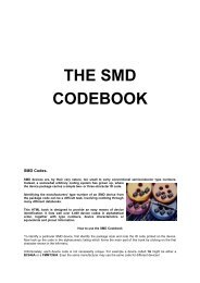
MARKING<br />
RC1206<br />
Fig. 1<br />
03<br />
Value = 10 KΩ<br />
E-24 series: 3 digits<br />
First two digits for significant figure and 3rd digit for number of zeros<br />
00<br />
Fig. 2 Value = 10 KΩ<br />
Both E-24 and E-96 series: 4 digits<br />
First three digits for significant figure and 4th digit for number of zeros<br />
For further marking information, please see special data sheet “Chip resistors marking”<br />
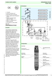
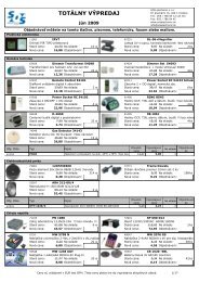
CONSTRUCTION<br />
The resistor is constructed on top<br />
of a high-grade ceramic body.<br />
Internal metal electrodes are added<br />
on each end to make the contacts to<br />
the thick film resistive element. The<br />
composition of the resistive element<br />
is a noble metal imbedded into a<br />
glass and covered by a second glass<br />
to prevent environment influences.<br />
The resistor is laser trimmed to the<br />
rated resistance value. The resistor<br />
is covered with a protective epoxy<br />
coat, finally the two external<br />
terminations (matte tin on Nibarrier)<br />
are added. See fig.3<br />
OUTLINES<br />
For dimension see Table 1<br />
H<br />
I 2<br />
I 1<br />
marking layer<br />
overcoat<br />
Primary glass layer<br />
resistive layer<br />
(Jumper chip is a conductor)<br />
inner electrode<br />
termination(Ni/matte tin)<br />
ceramic substrate<br />
overcoat<br />
W<br />
DIMENSIONS<br />
Table 1<br />
TYPE<br />
RC1206<br />
L (mm) 3.10 ± 0.10<br />
Fig. 3<br />
Chip resistor outlines<br />
L<br />
YNSC066<br />
W (mm) 1.60 ± 0.10<br />
H (mm) 0.55 ± 0.10<br />
I 1 (mm) 0.45 ± 0.20<br />
I 2 (mm) 0.40 ± 0.20<br />
Jul 02, 2009 V.4<br />
www.yageo.com
Product specification 5<br />
Chip Resistor Surface Mount<br />
RC<br />
SERIES<br />
1206 (RoHS Compliant)<br />
9<br />
ELECTRICAL CHARACTERISTICS<br />
Table 2<br />
CHARACTERISTICS<br />
RC1206 1/4 W<br />
Operating Temperature Range –55 °C to +155 °C<br />
Maximum Working Voltage<br />
200 V<br />
Maximum Overload Voltage<br />
400 V<br />
Dielectric Withstanding Voltage<br />
500 V<br />
5% (E24) 1 Ω to 22 MΩ<br />
Resistance Range<br />
1% (E24/E96) 1 Ω to 10 MΩ<br />
Zero Ohm Jumper < 0.05 Ω<br />
Temperature Coefficient<br />
1 Ω ≤ R ≤ 10 Ω<br />
10 MΩ < R ≤ 22 MΩ<br />
±200 ppm/°C<br />
±200 ppm/°C<br />
10 Ω < R ≤ 10 MΩ ±100 ppm/°C<br />
Jumper Criteria<br />
Rated Current<br />
2 A<br />
Maximum Current<br />
10 A<br />
FOOTPRINT AND SOLDERING<br />
PROFILES<br />
For recommended footprint and<br />
soldering profiles, please see the<br />
special data sheet “Chip resistors<br />
mounting”.<br />
PACKING STYLE AND PACKAGING QUANTITY<br />
Table 3 Packing style and packaging quantity<br />
PRODUCT TYPE PACKING STYLE REEL DIMENSION QUANTITY PER REEL<br />
RC1206 Paper Taping Reel (R) 7" (178 mm) 5,000 units<br />
10" (254 mm) 10,000 units<br />
13" (330 mm) 20,000 units<br />
NOTE<br />
1. For paper tape and reel specification/dimensions, please see the special data sheet “Chip resistors packing”<br />
FUNCTIONAL DESCRIPTION<br />
POWER RATING<br />
RC1206 rated power at 70°C is 1/4 W<br />
RATED VOLTAGE<br />
The DC or AC (rms) continuous working voltage<br />
corresponding to the rated power is determined by<br />
the following formula:<br />
V=√(P X R)<br />
or max. working voltage whichever is less<br />
Where<br />
V=Continuous rated DC or<br />
AC (rms) working voltage (V)<br />
P=Rated power (W)<br />
R=Resistance value (X)<br />
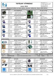
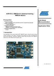
Fig. 4<br />
handbook, halfpage<br />
P<br />
(%P rated)<br />
100<br />
50<br />
0<br />
55 0<br />
50<br />
70 100<br />
MLB206_2<br />
155<br />
o<br />
T amb ( C)<br />
Maximum dissipation (P) in percentage of rated power as a<br />
function of the operating ambient temperature (T amb )<br />
Jul 02, 2009 V.4<br />
www.yageo.com
Product specification 6<br />
Chip Resistor Surface Mount<br />
RC<br />
SERIES<br />
1206 (RoHS Compliant)<br />
9<br />
TESTS AND REQUIREMENTS<br />
Table 4 Test condition, procedure and requirements<br />
TEST TEST METHOD PROCEDURE REQUIREMENTS<br />
Temperature<br />
Coefficient of<br />
Resistance<br />
(T.C.R.)<br />
IEC 60115-1 4.8<br />
At +25/–55 °C and +25/+125 °C<br />
Formula:<br />
R 2 –R 1<br />
T.C.R= ------------------------- ×10 6 (ppm/°C)<br />
R 1 (t 2 –t 1 )<br />
Where<br />
t 1 =+25 °C or specified room temperature<br />
t 2 =–55 °C or +125 °C test temperature<br />
R 1 =resistance at reference temperature in ohms<br />
R 2 =resistance at test temperature in ohms<br />
Refer to table 2<br />
Life/Endurance IEC 60115-1 4.25.1 At 70±5 °C for 1,000 hours, RCWV applied for<br />
1.5 hours on, 0.5 hour off, still air required<br />
±(1.0%+0.05 Ω) for 1% tol.<br />
±(3.0%+0.05 Ω) for 5% tol.<br />
Product specification 7<br />
Chip Resistor Surface Mount<br />
RC<br />
SERIES<br />
1206 (RoHS Compliant)<br />
9<br />
TEST TEST METHOD PROCEDURE REQUIREMENTS<br />
Board Flex/<br />
Bending<br />
IEC 60068-2-21<br />
Chips mounted on a 90mm glass epoxy resin<br />
PCB (FR4)<br />
2 mm bending<br />
Bending time: 60±5 seconds<br />
±(1.0%+0.05 Ω) for 1%, 5% tol.<br />
Product specification 8<br />
Chip Resistor Surface Mount<br />
RC<br />
SERIES<br />
1206 (RoHS Compliant)<br />
9<br />
TEST TEST METHOD PROCEDURE REQUIREMENTS<br />
Intermittent<br />
IEC 60115-1 4.39<br />
2.5 times of rated voltage or maximum ±(1.0%+0.05 Ω) for 1% tol.<br />
Overload<br />
overload voltage whichever is less for 1 second ±(2.0%+0.05 Ω) for 5% tol.<br />
on and 25 seconds off; total 10,000 cycles<br />
Product specification 9<br />
Chip Resistor Surface Mount<br />
RC<br />
SERIES<br />
1206 (RoHS Compliant)<br />
9<br />
REVISION HISTORY<br />
REVISION DATE CHANGE NOTIFICATION DESCRIPTION<br />
Version 4 Jul 02, 2009 - - Test Items and methods updated<br />
- Test requirements upgraded<br />
Version 3 Jul 15, 2008 - - Change to dual brand datasheet that describe RC1206 with RoHS compliant<br />
- Description of "Halogen Free Epoxy" added<br />
- Define global part number<br />
Version 2 Sep 03, 2004 - - New datasheet for 1206 thick film 1% and 5% with lead-free terminations<br />
- Replace the 1206 part of pdf files: RC01_11_21_31_5, RC02_12_22_32_10,<br />
and HRC01_5_4<br />
- Test method and procedure updated<br />
- PE tape added (paper tape will be replaced by PE tape)<br />
- High ohmic products combined into standard products.<br />
“ <strong>Yageo</strong> reserves all the rights for revising the content of this datasheet without further notification, as long as the products itself are unchanged. Any<br />
product change will be announced by PCN.”<br />
Jul 02, 2009 V.4<br />
www.yageo.com