Kramer Electronics Ltd. USER MANUAL ELECTRONIC SWITCHERS
Kramer Electronics Ltd. USER MANUAL ELECTRONIC SWITCHERS
Kramer Electronics Ltd. USER MANUAL ELECTRONIC SWITCHERS

You also want an ePaper? Increase the reach of your titles
YUMPU automatically turns print PDFs into web optimized ePapers that Google loves.
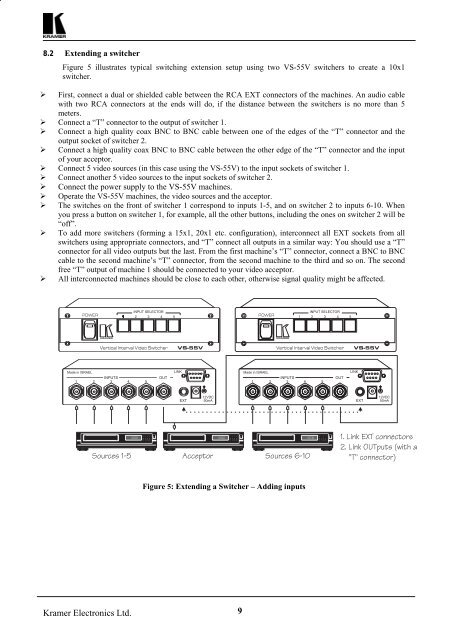
8.2 Extending a switcher<br />
Figure 5 illustrates typical switching extension setup using two VS-55V switchers to create a 10x1<br />
switcher.<br />
‣ First, connect a dual or shielded cable between the RCA EXT connectors of the machines. An audio cable<br />
with two RCA connectors at the ends will do, if the distance between the switchers is no more than 5<br />
meters.<br />
‣ Connect a “T” connector to the output of switcher 1.<br />
‣ Connect a high quality coax BNC to BNC cable between one of the edges of the “T” connector and the<br />
output socket of switcher 2.<br />
‣ Connect a high quality coax BNC to BNC cable between the other edge of the “T” connector and the input<br />
of your acceptor.<br />
‣ Connect 5 video sources (in this case using the VS-55V) to the input sockets of switcher 1.<br />
‣ Connect another 5 video sources to the input sockets of switcher 2.<br />
‣ Connect the power supply to the VS-55V machines.<br />
‣ Operate the VS-55V machines, the video sources and the acceptor.<br />
‣ The switches on the front of switcher 1 correspond to inputs 1-5, and on switcher 2 to inputs 6-10. When<br />
you press a button on switcher 1, for example, all the other buttons, including the ones on switcher 2 will be<br />
“off”.<br />
‣ To add more switchers (forming a 15x1, 20x1 etc. configuration), interconnect all EXT sockets from all<br />
switchers using appropriate connectors, and “T” connect all outputs in a similar way: You should use a “T”<br />
connector for all video outputs but the last. From the first machine’s “T” connector, connect a BNC to BNC<br />
cable to the second machine’s “T” connector, from the second machine to the third and so on. The second<br />
free “T” output of machine 1 should be connected to your video acceptor.<br />
‣ All interconnected machines should be close to each other, otherwise signal quality might be affected.<br />
Figure 5: Extending a Switcher – Adding inputs<br />
<strong>Kramer</strong> <strong>Electronics</strong> <strong>Ltd</strong>. 9