Product Information - Stator Service Polska
Product Information - Stator Service Polska
Product Information - Stator Service Polska

You also want an ePaper? Increase the reach of your titles
YUMPU automatically turns print PDFs into web optimized ePapers that Google loves.
<strong>Product</strong> <strong>Information</strong><br />
Motor and machine protection<br />
<br />
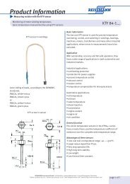
Temperature monitoring with PTC-thermistors<br />
Mechanical and electrical qualities<br />
Insulation class<br />
The insulation class of machines suitable for protection with PTC‘s is graded according to<br />
VDE 0530 and this is demonstrated in the table below.<br />
Insulating<br />
material class<br />
Y A E B F H C<br />
classified<br />
temperature limit<br />
+90°C +105°C +120°C +130°C +155°C +180°C<br />
more than<br />
+180°C<br />
insulation test<br />
resistance test<br />
of the installed<br />
thermistors<br />
installation instructions<br />
for electric<br />
motors<br />
Before testing the leads of the sensors have to be connected electroconductively. The testing<br />
voltage is connected to the leads and the motor winding according to DIN 44081 and DIN VDE<br />
0530.<br />
Because of the self-heating effect a method to measure PTC-thermistors must be used in which<br />
the voltage drop per sensor is not greater than 2,5V DC. The measurement is to be done with a<br />
measuring bridge, e.g. Wheatstone. A reading of ≤ 250 Ω per sensor indicates that the sensors<br />
and leads are correctly installed. When more than 1 sensor is wired in series the allowable<br />
resistance is in multiples of ≤ 250 Ω.<br />
It is important that the sensors are inserted in the stator coils, nearest to the rotor before<br />
impregnating the windings. The sensors should be tested prior to the impregnation of the<br />
rotor, winding temperatures must not exceed 175°C for sensors with ROT 160°C or 185°C for<br />
sensors with ROT 170°C. If impregnating agents or impregnating varnishes are used, that are<br />
not chemically neutral, the resistivity of the sensors has to be tested by the user. The sensor<br />
must be inserted in the middle of the end coils, ensuring that they are completely surrounded<br />
by the windings. Hollow space and trapped air influence the heat transmission. One sensor<br />
must be inserted into each leg of the windings with the leads parallel to the coil conductors.<br />
The mounting of several sensors has to be done in series. The leads must be connected to<br />
a terminal block on the terminal board, to ensure that they are separate from the winding<br />
terminals. Tension and other mechanical stresses must be avoided when installing sensors.<br />
Please avoid loops in the leads to avoid possibly occuring interfering voltage.<br />
Quality control<br />
Unless requested otherwise, quality control is to DIN 40080, AQL (acceptable quality level) in accordance with MILstandard<br />
105D and IEC 410 at the discretion of the manufacturer. Precise manufacturing and testing techniques guarantee<br />
the accuracy of REISSMANN-PTC-thermistors. All manufacturing operations are designed to conform to DIN 44081 +<br />
44082.<br />
Special versions (e.g. longer leads) are quickly available on request.<br />
Caution:<br />
The lead ends of the PTC-thermistors must not be connected to a voltage larger than 2,5 V DC!<br />
We recommend that a warning label be fixed to any apparatus where there is a possibility of more than 2,5 V DC being connected<br />
to the sensor. These warning labels may be purchased from REISSMANN when required.<br />
REISSMANN Sensortechnik GmbH · Schollenäcker 3 (unterm Wasserturm) · D-74538 Rosengarten-Uttenhofen<br />
Telefon +49 (0)791 950 15-0 · Telefax +49 (0)791 950 15-29 · E-Mail info@reissmann.com · Internet http://www.reissmann.com page of 8