

Download the October 2012 Issue in PDF format - Gear Technology ...
Download the October 2012 Issue in PDF format - Gear Technology ...
Download the October 2012 Issue in PDF format - Gear Technology ...

Create successful ePaper yourself
Turn your PDF publications into a flip-book with our unique Google optimized e-Paper software.
technical<br />
Figure 11<br />
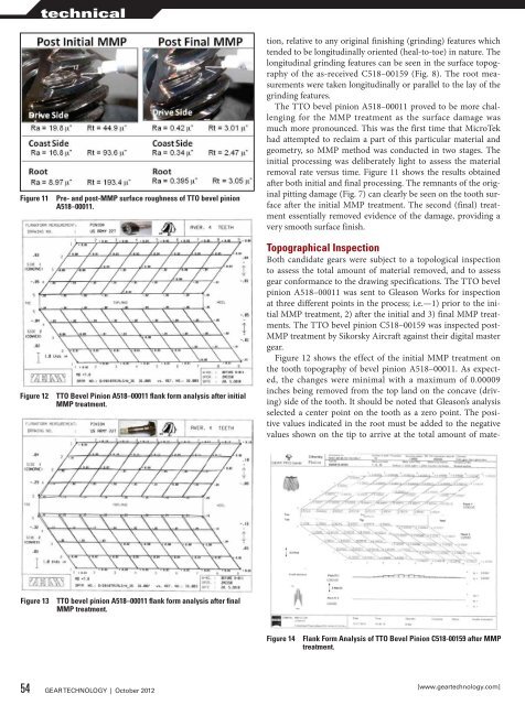
Figure 12<br />
Pre- and post-MMP surface roughness of TTO bevel p<strong>in</strong>ion<br />
A518–00011.<br />
TTO Bevel P<strong>in</strong>ion A518–00011 flank form analysis after <strong>in</strong>itial<br />
MMP treatment.<br />
tion, relative to any orig<strong>in</strong>al f<strong>in</strong>ish<strong>in</strong>g (gr<strong>in</strong>d<strong>in</strong>g) features which<br />
tended to be longitud<strong>in</strong>ally oriented (heal-to-toe) <strong>in</strong> nature. The<br />
longitud<strong>in</strong>al gr<strong>in</strong>d<strong>in</strong>g features can be seen <strong>in</strong> <strong>the</strong> surface topography<br />
of <strong>the</strong> as-received C518–00159 (Fig. 8). The root measurements<br />
were taken longitud<strong>in</strong>ally or parallel to <strong>the</strong> lay of <strong>the</strong><br />
gr<strong>in</strong>d<strong>in</strong>g features.<br />
The TTO bevel p<strong>in</strong>ion A518–00011 proved to be more challeng<strong>in</strong>g<br />
for <strong>the</strong> MMP treatment as <strong>the</strong> surface damage was<br />
much more pronounced. This was <strong>the</strong> first time that MicroTek<br />
had attempted to reclaim a part of this particular material and<br />
geometry, so MMP method was conducted <strong>in</strong> two stages. The<br />
<strong>in</strong>itial process<strong>in</strong>g was deliberately light to assess <strong>the</strong> material<br />
removal rate versus time. Figure 11 shows <strong>the</strong> results obta<strong>in</strong>ed<br />
after both <strong>in</strong>itial and f<strong>in</strong>al process<strong>in</strong>g. The remnants of <strong>the</strong> orig<strong>in</strong>al<br />
pitt<strong>in</strong>g damage (Fig. 7) can clearly be seen on <strong>the</strong> tooth surface<br />
after <strong>the</strong> <strong>in</strong>itial MMP treatment. The second (f<strong>in</strong>al) treatment<br />
essentially removed evidence of <strong>the</strong> damage, provid<strong>in</strong>g a<br />
very smooth surface f<strong>in</strong>ish.<br />
Topographical Inspection<br />
Both candidate gears were subject to a topological <strong>in</strong>spection<br />
to assess <strong>the</strong> total amount of material removed, and to assess<br />
gear conformance to <strong>the</strong> draw<strong>in</strong>g specifications. The TTO bevel<br />
p<strong>in</strong>ion A518–00011 was sent to Gleason Works for <strong>in</strong>spection<br />
at three different po<strong>in</strong>ts <strong>in</strong> <strong>the</strong> process; i.e.—1) prior to <strong>the</strong> <strong>in</strong>itial<br />
MMP treatment, 2) after <strong>the</strong> <strong>in</strong>itial and 3) f<strong>in</strong>al MMP treatments.<br />
The TTO bevel p<strong>in</strong>ion C518–00159 was <strong>in</strong>spected post-<br />
MMP treatment by Sikorsky Aircraft aga<strong>in</strong>st <strong>the</strong>ir digital master<br />
gear.<br />
Figure 12 shows <strong>the</strong> effect of <strong>the</strong> <strong>in</strong>itial MMP treatment on<br />
<strong>the</strong> tooth topography of bevel p<strong>in</strong>ion A518–00011. As expected,<br />
<strong>the</strong> changes were m<strong>in</strong>imal with a maximum of 0.00009<br />
<strong>in</strong>ches be<strong>in</strong>g removed from <strong>the</strong> top land on <strong>the</strong> concave (driv<strong>in</strong>g)<br />
side of <strong>the</strong> tooth. It should be noted that Gleason’s analysis<br />
selected a center po<strong>in</strong>t on <strong>the</strong> tooth as a zero po<strong>in</strong>t. The positive<br />
values <strong>in</strong>dicated <strong>in</strong> <strong>the</strong> root must be added to <strong>the</strong> negative<br />
values shown on <strong>the</strong> tip to arrive at <strong>the</strong> total amount of mate-<br />
Figure 13<br />
TTO bevel p<strong>in</strong>ion A518–00011 flank form analysis after f<strong>in</strong>al<br />
MMP treatment.<br />
Figure 14<br />
Flank Form Analysis of TTO Bevel P<strong>in</strong>ion C518-00159 after MMP<br />
treatment.<br />
54 GEAR TECHNOLOGY | <strong>October</strong> <strong>2012</strong><br />
[www.geartechnology.com]


