Full Catalog - Sealcon
Full Catalog - Sealcon
Full Catalog - Sealcon

Create successful ePaper yourself
Turn your PDF publications into a flip-book with our unique Google optimized e-Paper software.
*<br />
*<br />
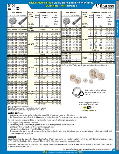
Nickel Plated Brass Liquid Tight Strain Relief Fittings<br />
Multi-Hole - NPT Threads<br />
CD16N1-BR CF16N1-BR<br />
3 3.0 .12 1.089.1600.19<br />
CD16N2-BR CF16N2-BR 3 4.0 .16 1.089.1601.19<br />
CD16N3-BR CF16N3-BR 4 4.0 .16 1.089.1602.19<br />
CD16N4-BR CF16N4-BR 5 4.0 .16 1.089.1603.19<br />
CD16N5-BR CF16N5-BR 6 4.0 .16 1.089.1604.19<br />
1/2” NPT<br />
CD16N6-BR CF16N6-BR 2 6.0 .24 1.089.1605.19<br />
(Enlarged)<br />
CD16N7-BR CF16N7-BR 3 5.6 .22 1.089.1606.19<br />
CD16N8-BR CF16N8-BR 6 3.0 .12 1.089.1607.19<br />
CD16N9-BR CF16N9-BR *4 3.0 .12 *1.089.1610.19<br />
CD16N0-BR CF16N0-BR 6 3.8 .15 1.089.1609.19<br />
CD16NP-BR CF16NP-BR Solid Insert 1.089.1699.19<br />
Dimensions and specifications may be changed without prior notice.<br />
www.sealconusa.com<br />
Part Numbers Thread Dimensions in Inches (mm)<br />
Part Numbers Thread Dimensions in Inches (mm)<br />
- 40 ºF to 212 ºF (- 40 ºC to 100 ºC) Type<br />
No. of Diameter Part<br />
- 40 ºF to 212 ºF (- 40 ºC to 100 ºC) Type<br />
No. of Diameter Part<br />
& Size<br />
Holes of Holes Numbers<br />
& Size<br />
Holes of Holes Numbers<br />
of<br />
of<br />
Inserts<br />
Inserts<br />
See page<br />
See page<br />
49 for thread<br />
only<br />
only<br />
Dome Flex<br />
** ** 49 for thread<br />
specs<br />
mm Inches<br />
Dome Flex specs<br />
mm Inches<br />
CD07AP-BR CF07AP-BR PG 7 / Solid Insert 1.089.0799.19<br />
CD21N1-BR CF21N1-BR<br />
4 6.0 .24 1.089.2100.19<br />
1/4” NPT<br />
CD21N2-BR CF21N2-BR 3 7.0 .28 1.089.2101.19<br />
CD21N3-BR CF21N3-BR 2 8.0 .31 1.089.2102.19<br />
CD09N1-BR CF09N1-BR<br />
4 1.4 .06 1.089.0900.19<br />
CD21N4-BR CF21N4-BR 4 5.0 .20 1.089.2103.19<br />
CD09N2-BR CF09N2-BR 2 3.0 .12 1.089.0901.19<br />
CD21N5-BR CF21N5-BR 1 8.0 .31 1.089.2104.19<br />
CD09N3-BR CF09N3-BR 5 1.6 .06 1.089.0902.19<br />
CD21N6-BR CF21N6-BR 3/4” NPT 4 5.2 .20 1.089.2105.19<br />
CD09N4-BR CF09N4-BR 2 1.7 .07 1.089.0903.19<br />
CD21N7-BR CF21N7-BR 3 5.2 .20 1.089.2106.19<br />
CD09N5-BR CF09N5-BR 10 1.4 .06 1.089.0904.19<br />
3/8” NPT<br />
CD09N6-BR CF09N6-BR 6 1.4 .06 1.089.0905.19 CD21N8-BR CF21N8-BR 4/1<br />
5.2 /<br />
3.7<br />
.20/.15 1.089.2107.19<br />
CD09N7-BR CF09N7-BR 3 1.7 .07 1.089.0906.19 CD21N9-BR CF21N9-BR 2 7.4 .29 1.089.2108.19<br />
CD09N8-BR CF09N8-BR 4 1.7 .07 1.089.0907.19 CD21NP-BR CF21NP-BR Solid Insert 1.089.2199.19<br />
CD09N9-BR CF09N9-BR 4 2.3 .09 1.089.0908.19<br />
CD09NP-BR CF09NP-BR Solid Insert 1.089.0999.19 CD29N1-BR -<br />
6 6.5 .26 1.089.2900.19<br />
*Note: This Insert has slotted holes.<br />
**Note: Flex Fittings are not a standard item, assembly required.<br />
*Note: CSA and CE Approvals only applies to Dome Fittings.<br />
CD29N2-BR - 4 9.0 .35 1.089.2901.19<br />
CD29N3-BR - 1” NPT 4 9.5 .37 1.089.2902.19<br />
CD29N9-BR - 2 11 .43 1.089.2908.19<br />
CD29NP-BR - Solid Insert 1.089.2999.19<br />
CD13N1-BR CF13N1-BR<br />
3 2.0 .08 1.089.1300.19<br />
CD13N2-BR CF13N2-BR 6 3.0 .12 1.089.1301.19<br />
CD13N3-BR CF13N3-BR 3 4.0 .16 1.089.1302.19<br />
CD13N4-BR CF13N4-BR 2 5.0 .20 1.089.1303.19<br />
For Strain Relief Fitting specifications and dimensions see Page 14.<br />
CD13N5-BR CF13N5-BR 3 3.0 .12 1.089.1304.19<br />
1/2” NPT<br />
CD13N6-BR CF13N6-BR 2 5.2 .20 1.089.1305.19<br />
CD13N7-BR CF13N7-BR 2 3.8 .15 1.089.1306.19<br />
CD13N8-BR CF13N8-BR 2 4.2 .17 1.089.1307.19<br />
CD13N9-BR CF13N9-BR 2 2.5 .10 1.089.1308.19<br />
CD13NP-BR CF13NP-BR Solid Insert 1.089.1399.19<br />
Optional Locking Nuts & Other<br />
Accessories starting on Page<br />
28 - 39.<br />
Dome Fittings also available<br />
with the following approvals:<br />
www.sealconex.com<br />
Custom Solutions!<br />
• Any special insert hole or profile configuration is available for a minimum order of 1,000 pieces.<br />
• No Charge Manufacturing Fee - In 12-14 weeks or a one time Expedite Fee reducing manufacturing to 6-8 weeks.<br />
For small quantities we suggest drilling or machining the inserts yourself, following these guidelines:<br />
• We suggest drilling the frozen solid insert.<br />
• Drill holes by using a standard high-speed steel drill bit of the proper size at approx. 2500 RPM.<br />
• Drill holes with insert installed in Strain Relief Fitting as a fixture.<br />
• Keep a minimum distance of 1 mm (.04 in) between holes.<br />
• The outside holes can be located right against the lip of the strain relief body, as sufficient insert material remains between the hole and the body wall<br />
due to the design of the cord grip.<br />
Important:<br />
Design Parameters: Cable diameter should not be less than 80% of hole diameter and the difference between hole and cable diameter should never exceed<br />
.04” (1 mm). The Multi Cable fittings will meet NEMA 4x = IP65 if the design parameters are complied with.<br />
To verify a submersible NEMA 6= IP68 application, the final assembly of cables and fittings must be tested by the customer or submitted at the customer’s<br />
expense to an independent test lab.<br />
For Material Specifications and Approval Information, please refer to page 45.<br />
23<br />
Nylon Strain Relief Nickel Plated Brass PVDF / Steel Accessories Adapter,Reducer,Enlarger Conduit System Technical Information Other Products / Index