Which Tube Shall I Use - Tube CAD Journal
Which Tube Shall I Use - Tube CAD Journal
Which Tube Shall I Use - Tube CAD Journal
You also want an ePaper? Increase the reach of your titles
YUMPU automatically turns print PDFs into web optimized ePapers that Google loves.
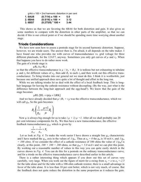
g/4α x 100 = 2nd harmonic distortion in per cent<br />
1. 6AU6 (0.7/14) x 100 = 5.0<br />
2. 6BA6 (0.5/16) x 100 = 3.12<br />
3. 6BS7 (0.275/8) x 100 = 3.44<br />
This shows us that we are favoring the 6BA6 for both distortion and gain. It also gives us<br />
some numbers to compare with the distortion in other parts of the amplifier, so that we can<br />
decide if this is our critical point or if we should be spending more time worrying about another<br />
stage.<br />
Triode Considerations<br />
We have now seen how to assess a pentode stage for its second harmonic distortion. Suppose,<br />
however, we are triode users. The answer then is, I'm afraid, it all depends on the tube maker. I<br />
have found one who provides me with curves of transconductance vs. grid voltage for three<br />
different plateloads, for the 12AT7, anyway. Sometimes you only get curves of µ and r p . When<br />
that happens you have to do rather more work.<br />
The gain of a triode stage is<br />
µR L /(r p +R L )<br />
so that the effective transconductance is µ / (r p + R L ) . It is tedious but not exhausting to tabulate<br />
µ and r p for different values of e g , then add R L to each r p and then work out this effective transconductance.<br />
To bring triodes into our general net we must do this. I think it is worthwhile, just<br />
because one unified approach does save quite a lot of thought and effort in the long run.<br />
While we are talking triodes let us deal with the effect of a local feedback loop. This is longhair<br />
language for leaving the cathode resistance without decoupling. (By the way, just what is the<br />
difference between the long-hair approach and the egg-head?). We know that the gain of the<br />
stage becomes<br />
µRL/[RL + rp(µ + 1)RK]<br />
And we have already decided that µ/ (R L + r p ) was the effective transconductance, which we<br />
will call g m . So the gain becomes<br />
⎛ 1 µ + 1 ⎞<br />
R<br />
⎜ + ⎟<br />
L/<br />
Rk<br />
⎝gm<br />
µ ⎠<br />
Now µ is always big enough for us to take ( µ + 1) µ =1. After all we shall probably use 20<br />
per cent tolerance components for R K . We thus have a new transconductance, the effective<br />
feedback transconductance g mf , which is given by<br />
1 = 1 + Rk<br />
g g<br />
mf<br />
m<br />
Let us look at Fig. 4. To make the work easier I have drawn a straight line g m characteristic<br />
and I have marked the g m , axis in the values of 1/g m . Thus at e g = 0 the g m is 10 mA/v, and 1/g m<br />
= 100 ohms. If we consider the effect of a cathode resistance of 100 ohms the value of 1/g m f is<br />
clearly, at this point, 100 + 100 = 200 ohms, so that g mf = 5.0 mA/v and we can plot this point.<br />
By working out a reasonable number of values in this way you can quite easily sketch in the<br />
curves shown in Fig. 4. You can do this for a pentode on the ordinary transconductance curve,<br />
and for a triode on the effective transconductance curve described earlier in this article.<br />
There is a rather interesting thing which appears if you draw out this set of curves very<br />
carefully, very large. When you work out the figure of merit for a swing from e g = o to e g =-2.5<br />
for the tube alone and for the tube with a 100-ohm cathode resistor, there is a small advantage in<br />
favor of the tube alone. It is less than 10 per cent better, which is not very much, of course. But<br />
the feedback does not quite reduce the distortion in the same proportion as it reduces the gain.


