Installation Instructions for 30-4300 AEM Serial Gauge
Installation Instructions for 30-4300 AEM Serial Gauge
Installation Instructions for 30-4300 AEM Serial Gauge

You also want an ePaper? Increase the reach of your titles
YUMPU automatically turns print PDFs into web optimized ePapers that Google loves.
You can purchase this part at: http://thmotorsports.com<br />
Congratulations, the 52MM (2 1/16”) <strong>AEM</strong> <strong>Serial</strong> <strong>Gauge</strong> features a three digit LED<br />
digital readout with 24 sweeping multi color LED’s, and two input buttons. Also included<br />
in the box are all the necessary wiring cables and brackets to install and use the gauge.<br />
A non-limited fully functional version of Pro <strong>Gauge</strong> software by <strong>AEM</strong> is also in the box.<br />
The <strong>AEM</strong> <strong>Serial</strong> <strong>Gauge</strong> allows users to monitor up to 19 different parameters. In<br />
addition, users can “daisy chain” multiple gauges together using the included harness.<br />
Contents:<br />
(1) <strong>Serial</strong> <strong>Gauge</strong> assembly<br />
(1) Appearance kit (Silver bezel, silver pin guide, white faceplate)<br />
(1) <strong>Installation</strong> kit ( Butt connector, 6 pieces)<br />
(1) <strong>Serial</strong> <strong>Gauge</strong> adapter cable<br />
(1) <strong>Serial</strong> <strong>Gauge</strong> flying lead<br />
(1) Instruction manual<br />
(1) Pro <strong>Gauge</strong> by <strong>AEM</strong> installation CD<br />
(1) DB9 Female Female adapter cable<br />
Getting Started<br />
NOTE: The <strong>Serial</strong> <strong>Gauge</strong> only works with version 1.19 and newer EMS firmware.<br />
<strong>Installation</strong><br />
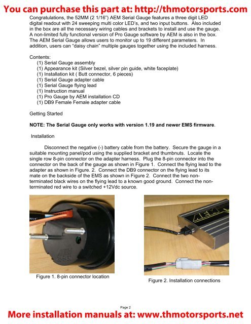
Disconnect the negative (-) battery cable from the battery. Secure the gauge in a<br />
suitable mounting panel/pod using the supplied bracket and thumbnuts. Locate the<br />
single row 8-pin connector on the adapter harness. Plug the 8-pin connector into the<br />
connector on the back of the gauge as shown in Figure 1. Connect the flying lead to the<br />
adapter as shown in Figure. 2. Connect the DB9 connector on the flying lead to its<br />
mate on the backside of the EMS as shown in Figure 2. Connect the two nonterminated<br />
black wires on the flying lead to a known good ground. Connect the nonterminated<br />
red wire to a switched +12Vdc source.<br />
Figure 1. 8-pin connector location<br />
Figure 2. <strong>Installation</strong> connections<br />
Page 2<br />
More installation manuals at: www.thmotorsports.net