ESD Brochure - Polyflor
ESD Brochure - Polyflor
ESD Brochure - Polyflor

Create successful ePaper yourself
Turn your PDF publications into a flip-book with our unique Google optimized e-Paper software.
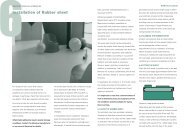
POLYFLOR SD PRODUCTS<br />
Figure 1, shows the method of installation using grounding<br />
strip, where conductance to ground is specified.<br />
<strong>Polyflor</strong> <strong>ESD</strong> products can be used in conjunction with<br />
150mm<br />
static control clothing, footwear and wrist straps; special<br />
workstations; ionisers and humidity controllers.<br />
They are available in sheet format or as 608 x 608mm<br />
tiles: the preferred size for use on access flooring.<br />
Installation is obviously critical, but it can be carried out<br />
by any competent commercial flooring contractor, using<br />
known and accepted procedures and <strong>Polyflor</strong> approved<br />
adhesives.<br />
GROUND<br />
F I G U R E 1<br />
20 METRES 20 METRES<br />
POLYFLOR EC PRODUCTS<br />
Figure 2, shows the method of installation where<br />
conductance to ground is specified. The grounding strip<br />
need only extend along the floor for 150mm .<br />
150mm<br />
GROUNDING<br />
STRIP<br />
It is important that the correct <strong>Polyflor</strong> product<br />
is selected to meet the specification required.<br />
For information and advice on all issues concerning<br />
static control flooring, installation techniques, and<br />
testing procedures, please contact our trained technical<br />
staff, who will be pleased to help you.<br />
GROUNDING STRIP<br />
GROUND<br />
POLYFLOR SD - CLEAN ROOM<br />
F I G U R E 2<br />
150mm<br />
MIN<br />
POLYFLOR CONDUCTIVE ROF<br />
Figure 3, shows the method of installation to a grounding<br />
grid: an essential requirement for this product.<br />
150mm<br />
GROUND<br />
GROUND<br />
150mm<br />
GRID SPACING<br />
600mm<br />
F I G U R E 3<br />
Figure 4 shows typical connection of the grounding grid to<br />
the building ground point.<br />
BRASS/COPPER<br />
NUT AND BOLT<br />
WITH TWO WASHERS<br />
GROUND WIRE WITH<br />
CRIMP ON EYE<br />
WASHER<br />
NUT<br />
ELECTRICAL BOX<br />
BOLTED TO WALL<br />
F I G U R E 4<br />
BRASS GROUNDING FOIL FOLDED<br />
BACK ON ITSELF. THEN HOLE<br />
PUNCHED THROUGH, TO TAKE BOLT.