Miata piggy back ECU installation & tuning - Flyin
Miata piggy back ECU installation & tuning - Flyin
Miata piggy back ECU installation & tuning - Flyin

You also want an ePaper? Increase the reach of your titles
YUMPU automatically turns print PDFs into web optimized ePapers that Google loves.
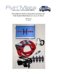
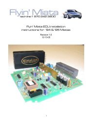
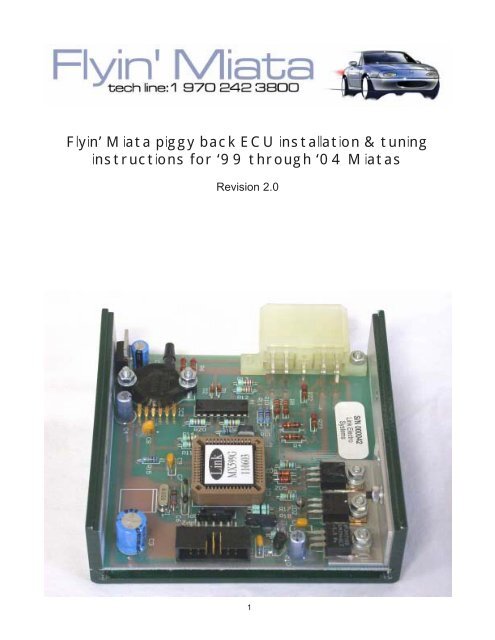
<strong>Flyin</strong>’ <strong>Miata</strong> <strong>piggy</strong> <strong>back</strong> <strong>ECU</strong> <strong>installation</strong> & <strong>tuning</strong><br />
instructions for ‘99 through ‘04 <strong>Miata</strong>s<br />
Revision 2.0<br />
1
Contents<br />
Section 1: Introduction .........................................................................3<br />
Required tools .....................................................................3<br />
Section 2: <strong>ECU</strong> <strong>installation</strong>...................................................................4<br />
Section 3: O2 Signal Modifier and A/F Meter .......................................9<br />
Section 4: Required Knowledge .........................................................12<br />
Section 5: Chip Installation Instructions .............................................13<br />
Section 6: Introduction to the Keypad ................................................14<br />
Section 7: Setting Up the <strong>ECU</strong> for Your Car.......................................15<br />
Section 8: Boost Controls...................................................................17<br />
Section 9: Advanced Tuning ...............................................................20<br />
Tuning with a wide band O2 sensor ....................................20<br />
Ignition timing .....................................................................20<br />
Section 10: Table 1 Defaults ..............................................................22<br />
Section 11: Table 2 Defaults ...............................................................23<br />
Section 12: Definition of Zones ..........................................................24<br />
Section 13: Operation warnings .........................................................27<br />
2
Section 1: Introduction<br />
The <strong>Flyin</strong>’ <strong>Miata</strong> <strong>piggy</strong> <strong>back</strong> <strong>ECU</strong> drives four auxiliary fuel injectors and provides tunable ignition<br />
retard based on a 16 column and 6 row map of engine RPM and manifold pressure. The<br />
<strong>ECU</strong> also provides turbo boost pressure control. A hand-held keypad in the cockpit allows<br />
adjusting of all the operating parameters.<br />
We have made the <strong>piggy</strong> <strong>back</strong> <strong>installation</strong> as easy as possible by using plug-in connections<br />
where ever possible. However, some wires will still need to be cut and spliced at the <strong>ECU</strong>. On<br />
2001 through 2003 cars, the wires going to the ignition coils need to be cut and spliced as well,<br />
in order for the Link <strong>piggy</strong> <strong>back</strong> to intercept the ignition signal.<br />
For the wire splicing called for in this manual we recommend, and include, heat shrinkable<br />
crimp connectors. A crimp connection is better both structurally and electrically than a solder<br />
connection. If you do not believe us, try to find one soldered connection in the entire wire<br />
harness in your <strong>Miata</strong>. The integrity of a crimp connection depends on the quality of the tools<br />
used for the <strong>installation</strong>. Go to Sears and invest in a high quality pair of wire crimping pliers.<br />
These can be bought for $25 to $30 and will quickly pay for themselves in this and future<br />
projects.<br />
The included crimp connectors use a heat shrinkable coating. Once the wires are crimped in<br />
place, heat the connector with a heat gun (buy one of these at Sears with your crimping tool)<br />
to shrink down the outer covering. This will provide a water tight seal for the life of your car.<br />
Required tools<br />
Every project on your <strong>Miata</strong> presents the opportunity to purchase more tools. Below are the<br />
tools you will need for the successful <strong>installation</strong> of this <strong>ECU</strong>.<br />
metric open/box wrenches<br />
metric socket set<br />
assorted slot and phillips screw drivers<br />
metric allen wrenches<br />
utility knife<br />
wire crimp tool<br />
wire strippers<br />
heat gun<br />
3
Section 2: <strong>ECU</strong> <strong>installation</strong><br />
1) Disconnect the negative battery terminal.<br />
2) Inside the car remove the glove box by firmly pulling on the right side of the box to disengage<br />
the hinge. Also, remove the metal plate under the steering column by removing the two<br />
screws at the very bottom and gently pulling down on it.<br />
One end of the harness included with the <strong>piggy</strong><strong>back</strong> <strong>ECU</strong> has 9 metal terminals, one on each<br />
wire. On the other end of the harness, all the wires are pre-terminated with the appropriate<br />
connectors for their associated function. This harness will go through the firewall alongside of<br />
the lower AC line.<br />
3) With a sharp knife, cut the rubber grommet around the lower AC line and remove it.<br />
4) Cover the end of the harness with the 9 metal connectors with a piece of plastic secured<br />
with a zip tie. Run this end of the harness through the space around the AC line.<br />
5) Pull at least 20” of wire though the firewall to reach the floor inside the car. This will allow<br />
enough wire under the hood for all the connections and still give you plenty of wire to work with<br />
inside the car.<br />
6) Remove the empty plastic connector from the<br />
plug on the <strong>ECU</strong>. All the wires must be loaded into<br />
the plastic connector. Use the diagram on the next<br />
page for the position of the wires. The diagram<br />
refers to the wire colors when viewed from the<br />
wire side of the plug with the tap on top. Refer<br />
to the photo on the right, the brown/white wire will<br />
4
TAB<br />
Brown/ Thick White/<br />
White Black Green Blue<br />
Green/<br />
Thin<br />
Orange Blue Yellow Red Black<br />
Wire positions in the wire harness for the <strong>piggy</strong> <strong>back</strong> <strong>ECU</strong><br />
be in the upper left corner.<br />
In the engine bay there will be 4 wire<br />
bundles with connectors on the ends. They<br />
are run through the engine bay as follows.<br />
7) Run the two black wires with ring terminals<br />
on the end and the wires with the grey<br />
plastic connectors down along the factory<br />
wire harness bundle between the cam cover<br />
and the intake manifold.<br />
8) The two black wires with ring terminals<br />
are ground wires for the <strong>ECU</strong>. At the front of<br />
the motor, connect both ring terminals under<br />
the bolt for the ground connection at the<br />
throttle body.<br />
NOTE: On ’99 & ’00 cars perform step 9 and skip steps 10 through 14. On ’01<br />
through ‘04 cars skip step 9 and perform steps 10 through 14.<br />
9) On ’99 and ’00 cars there is a gray four wire connector on the front of the timing cover,<br />
pull the two halves apart and plug the gray connectors on the new harness in between them.<br />
This is where the Link <strong>ECU</strong> intercepts the factory ignition signal.<br />
5
10) On ’01 to ’04 cars the ignition system<br />
was changed to a coil-on-plug design. We<br />
will need to tap into the factory wire harness<br />
for the ignition signals on top of the cam<br />
cover. The wire diagram is shown above.<br />
Note: To access the wires called for from<br />
the Link <strong>ECU</strong>, cut the two grey plugs off the<br />
harness as shown in the photo to the right.<br />
11) On ’01 to ’04 cars the factory <strong>ECU</strong><br />
drives the number one coil with a brown/<br />
yellow wire. Cut the brown/yellow wire.<br />
Using the red butt connectors, connect the<br />
green wire to the <strong>ECU</strong> end of the brown/yellow wire and the blue wire to the coil end of the<br />
brown/yellow wire.<br />
12) On ‘01 to ‘04 cars the factory <strong>ECU</strong> drives the number two coil with a black/yellow wire.<br />
Cut the black/yellow wire. Using the red butt connectors connect the white/blue wire to the<br />
<strong>ECU</strong> end of the black/yellow wire and the green/yellow wire to the coil end of the black/yellow<br />
wire.<br />
6
13) On ‘01 to ‘04 cars connect the red wire from the Link harness to the black/white wire in<br />
the car’s harness with the quick splice connector supplied. This will provide 12 volts for the<br />
Link <strong>ECU</strong> to operate. Do not cut the black/white wire, just tap into it.<br />
14) The white connector with red and orange wires is for the auxiliary fuel injectors. Run this<br />
pair along the passenger side fender and connect it to the harness on the fuel injectors. Connect<br />
each leg of the fuel injector harness to each fuel injector.<br />
15) Run the red and brown/white<br />
wires, for the boost control solenoid,<br />
across to the driver’s side of the<br />
engine bay along the steel line for the<br />
brake vacuum booster. If this <strong>installation</strong><br />
is not using the Link’s boost<br />
control feature, simply tuck the pair of<br />
wires for the boost control solenoid<br />
out of the way. They will not be used.<br />
16) On FM2 turbo <strong>installation</strong>s,<br />
mount the boost control solenoid to<br />
the rear of the baffle around the<br />
intake air filter using a 6mm bolt<br />
through the hole in the baffle. Plug<br />
the wires into the harness run along<br />
the firewall in the previous step.<br />
17) The boost control solenoid needs a pressure signal source after the turbo. On our FM2<br />
turbo kits a 1/4” hose barb is mounted on the turbo for this purpose. Use the 1/4" hose, supplied<br />
in bag 13A, to connect to the brass fitting on the solenoid.<br />
18) Connect the black plastic fitting at the opposite end of the solenoid, pointing at a right<br />
angle to the brass fitting, to the wastegate actuator on the turbo. The second plastic fitting<br />
pointing straight out the end of the solenoid<br />
vents to atmosphere. Leave it open.<br />
19) Secure the connections of the hoses with<br />
wire ties. If these hoses blow off, control of the<br />
wastegate will be lost and the turbo will make<br />
enough boost to damage the engine.<br />
20) Take the <strong>piggy</strong> <strong>back</strong> <strong>ECU</strong> into the passenger<br />
side of the car. Plug the wire harness, the<br />
ribbon cable, and the vacuum hose into the<br />
<strong>ECU</strong>.<br />
21) Mount the Link <strong>ECU</strong> behind the glove<br />
box. On ‘99 &’00 cars the rear of the AC box<br />
provides a large flat space to locate the <strong>ECU</strong><br />
7
with double-sided tape, as shown in the photo<br />
to the right. On ‘01 and later cars slip the <strong>ECU</strong><br />
between the AC box and the AC fan housing.<br />
8
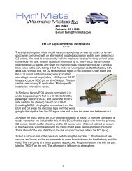
Section 3: O2 Signal Modifier and A/F Meter<br />
The O2 signal modifier is a small device that intercepts the factory O2 sensor signal before the<br />
factory <strong>ECU</strong>. It sends a conditioned signal to the <strong>ECU</strong> when the motor operates in boost to<br />
keep the factory <strong>ECU</strong> from “seeing” the additional fuel necessary under boost. An air/fuel (A/<br />
F) meter is also included to monitor the air fuel ratio when operating under boost.<br />
The metal panel under the steering column and the glove box should still be removed from<br />
the last section. The factory <strong>ECU</strong> is located under the dash board on the driver’s side of the<br />
car right above the clutch pedal. Standing on your head to work on the car will be necessary<br />
for this section. Use the supplied electrical connectors to connect the A/F meter and the O2<br />
signal modifier as follows. Refer to the diagrams on pages 10 &11 for the wire connections<br />
and the identification of the <strong>ECU</strong> terminals to be used.<br />
O2 Signal Modifier:<br />
1) Remove the three harness plugs from the<br />
<strong>ECU</strong> and cut off some of the electrical tape<br />
around the wires. This will allow you to separate<br />
them and access the individual wires<br />
needed for this operation.<br />
2) The first wire we are interested in is the blue<br />
wire in terminal A. This is the front O2 sensor<br />
signal wire. Cut the wire about two inches out<br />
from the <strong>ECU</strong> connector and strip ¼” of insulation<br />
off both ends.<br />
3) Crimp the blue wire on the O2 signal modifier<br />
to the <strong>ECU</strong> end of the cut blue wire in Terminal A using the supplied butt connector.<br />
4) Crimp the yellow wire from the O2 signal modifier to the O2 sensor end of the blue wire in<br />
terminal A using the supplied butt connector.<br />
5) Connect the red wire from the O2 signal modifier to the white/red wire in terminal B using<br />
the supplied quick splice connector.<br />
6) Connect the black wire from the O2 signal modifier to the black/red wire in terminal C using<br />
the supplied quick splice connector.<br />
7) The pressure switch on the O2 signal modifier needs a pressure signal from the intake<br />
manifold. Use the “T” fitting to tap into the vacuum hose in to the signal line run through the<br />
fire wall for the boost gauge.<br />
8) If the Lambda Link A/F meter is not being used, jump to step 13.<br />
9
Lambda Link A/F meter:<br />
It is convenient to store the A/F meter in the<br />
glove box when not using it. If you wish to do<br />
this, run the wires from the glove box area over<br />
to the driver’s side of the car behind the dash.<br />
9) Connect the white wire from the A/F meter to<br />
the yellow wire from the O2 signal modifier<br />
using the supplied quick splice connector.<br />
10) Connect the red wire from the A/F meter to<br />
the red wire on the O2 signal modifier using the<br />
supplied quick splice connector.<br />
11) Connect the black wire from the A/F meter to the black wire on the O2 signal modifier<br />
using the supplied quick splice connector.<br />
12) Connect the green wire from the A/F meter to the black/blue wire in terminal D using the<br />
supplied quick splice connector.<br />
13) Use the tape on the <strong>back</strong> of the O2 signal modifier box to attach it to the side of the <strong>ECU</strong><br />
case. Zip tie the switch to a nearby wire harness and plug the <strong>ECU</strong> connectors <strong>back</strong> into the<br />
<strong>ECU</strong>.<br />
14) Reinstall the glove box.<br />
10
Section 4: Required Knowledge<br />
The <strong>Flyin</strong>’ <strong>Miata</strong> <strong>piggy</strong> <strong>back</strong> <strong>ECU</strong> is pre-programmed from <strong>Flyin</strong>’ <strong>Miata</strong> so that minimal <strong>tuning</strong><br />
time is needed to get the car up and running. Reading and following sections 6,7, & 8 are<br />
required to get the car running. Section 11 offers detailed information about all of the parameters<br />
the <strong>ECU</strong> controls and should answer any questions that arise about the operation of the<br />
<strong>piggy</strong> <strong>back</strong> <strong>ECU</strong>.<br />
Important things to know about the FM <strong>piggy</strong> <strong>back</strong> <strong>ECU</strong>:<br />
1) The <strong>Flyin</strong>’ <strong>Miata</strong> <strong>piggy</strong><strong>back</strong> <strong>ECU</strong> activates when the engine operates above a user adjustable<br />
manifold pressure, normally atmospheric pressure, 0 psi on the boost gauge. At this<br />
point the <strong>ECU</strong> fires four auxiliary fuel injectors, intercepts and delays the ignition signal, and<br />
controls the turbo boost pressure. All these functions are user programmable with a hand-held<br />
key pad included with the system.<br />
2) The <strong>piggy</strong> <strong>back</strong> <strong>ECU</strong> uses an on-board MAP (Manifold Absolute Pressure) sensor to measure<br />
the intake manifold pressure.<br />
3) The <strong>ECU</strong> uses memory locations called “zones” for all its operating parameters. Tables of<br />
all the zones with their default values can be found in sections 9 & 10. Commonly used zones<br />
are listed in the main menu, accessible with the hand held keypad, with a descriptive title. All<br />
zones can be accessed from the EDIT Z menu found at the end of the menu list using the<br />
keypad.<br />
4) The <strong>ECU</strong> includes 2 different default settings to get the car up and running quickly. One for<br />
turbocharged (Table 2) and one for supercharged (Table 1) applications.<br />
5) The <strong>ECU</strong> measures pressure in kilo Pascals (kPa) with approximately 100 kPa equaling<br />
atmospheric pressure at sea level. The <strong>ECU</strong> measures temperatures in degrees Centigrade.<br />
6) To make understanding the manual easy, memory locations displayed in the main menu on<br />
the keypad are shown in red. Memory locations not displayed in the main menu are in blue<br />
and can only be modified from the EDIT Z menu.<br />
12
Section 5: Chip Installation Instructions<br />
Note: When installing a new <strong>ECU</strong> for the first time, skip this section. The microprocessor has<br />
already been installed before the <strong>ECU</strong> was shipped. This procedure only applies when upgrading<br />
to new software after the <strong>ECU</strong> has been installed.<br />
To remove the microprocessor a chip puller must be used. Using paperclips, etc. to try to<br />
remove the chip will probably damage the chip or socket. Radio Shack sells a 52-pin PLCC<br />
puller for less than $5. Buy one.<br />
The microprocessor can be found in the picture of the circuit board below. Insert the two<br />
prongs of the puller into the openings in the corners of the socket and squeeze the puller. The<br />
chip will pop out.<br />
After removing the old chip with the proper puller, install the new chip by pressing it into place<br />
firmly with your thumb. The chip must be properly oriented. If you look very closely at the<br />
edges of the chip, you will see that one edge is beveled and has a small dot in the middle of<br />
the edge. This is the top of the chip. With the multiplug on the printed circuit board at the<br />
bottom right corner, the top of the chip should be up.<br />
Once the chip is in<br />
place, replace the cover<br />
on the <strong>ECU</strong> case and go<br />
to the next section of the<br />
manual.<br />
13
Section 6: Introduction to the Keypad<br />
The keypad included with the system is the only way to see and alter the settings. There are<br />
three pairs of keys:<br />
The SELECT keys move through the main menu. When turning on the car, the <strong>ECU</strong> always<br />
wakes up in the RPM screen. This is considered the beginning of the main menu. Use the up<br />
and down keys to scroll through the menu choices. When it gets to the end of the main menu<br />
(where it says “EDIT Z0 XX”), it will stop.<br />
Once the desired screen has been found, changes are made to the setting by using the AD-<br />
JUST keys. Some screens don’t have any adjustable parameters in them, they are read only.<br />
The ADJUST keys are used to access additional information in some of these screens, for<br />
instance in the RPM screen, pressing the ADJUST down key accesses the current manifold<br />
pressure (MAP).<br />
The EDIT menu is a submenu of less often used parameters. It is accessed by holding the<br />
SELECT up key until it stops. At this point, the screen will display “EDIT Z0 XX”. You move<br />
through this menu by using the EDIT up and down keys. To make changes, use the ADJUST<br />
keys, just like in the main menu.<br />
Storing: When ever a change is made in the <strong>ECU</strong> it must be stored or the change will be lost<br />
when the car is turned off. There are two ways to store information. Storing will only occur at<br />
idle. First is in the STORE screen. In this screen press both ADJUST keys until the screen<br />
fills with asterisks, then release the ADJUST keys. The second way to store is in the EDIT Z<br />
menu. In any screen in the EDIT Z menu press both EDIT keys and the screen will fill with<br />
asterisks signaling that the new information is being saved. In both cases, the keys to initiate<br />
the save function can be released as soon as the asterisks appear.<br />
14
Section 7: Setting Up the <strong>ECU</strong> for Your Car<br />
1) Load Default values: The <strong>ECU</strong> contains 2 sets of default values to help speed along the<br />
<strong>tuning</strong> process. Turn the car “on” but do not start the engine. Scroll to the screen that displays<br />
RELOAD TABLE 1. Table 1 is for supercharged cars and Table 2 is for turbocharged cars.<br />
Press the adjust down key to switch to Table 2 for turbocharged cars.<br />
2) Press the select up key once to go to the RELOAD screen. Here, press and hold both<br />
adjust keys until the screen fills with asterisks, then release the adjust keys. This loads the<br />
default settings into the <strong>ECU</strong>.<br />
3) Check MAP SENSOR operation: In the RPM screen press the adjust down key on the<br />
keypad to display the MAP sensor reading. At sea level the MAP reading should be about<br />
100kPa. Higher elevations will read lower values. The MAP sensor has an accuracy window<br />
of +/-5kPa. Refer to the table below for the atmospheric pressure at different elevations.<br />
Elevation (ftX1000) 0 1 2 3 4 5 6 7 8 9<br />
Pressure (kPa) 100 97 94 91 87 84 80 77 74 71<br />
4) Set ONSET: Go to the ONSET screen and set it to 100kPa using the adjust keys. This<br />
sets the <strong>piggy</strong><strong>back</strong> to start making is fuel and timing changes at 0 on the boost gauge. Below<br />
ONSET the car operates completely on the stock <strong>ECU</strong> and fuel injectors.<br />
5) Set the boost target: Go to the BOOST screen and set it to 100kPa. This will limit the<br />
boost to the value set by the mechanical wastegate controller on the turbo or the external<br />
waste gate. This will be about 6psi on an FM2 turbo kit. Setting the <strong>ECU</strong> up to raise the boost<br />
pressure will be covered in the next section.<br />
6) Store these changes.<br />
7) Start the car and check for fuel leaks around the junction of the auxiliary fuel injectors with<br />
the fuel rail.<br />
8) Check the vacuum signal: Go to ONSET screen and check the number in parentheses.<br />
This measurement is the vacuum in the intake manifold at idle. The reading should be steady<br />
between 25kPa and 35kPa. If you do not have a reliable map signal, nothing in the <strong>ECU</strong> will<br />
work correctly.<br />
Note: The fuel numbers loaded into memory have been developed on our<br />
Dynojet chassis dynamometer with a wide band O2 sensor. These are more<br />
accurate than what can be obtained from the air/fuel meter supplied with the kit,<br />
using the stock O2 sensor in the car. These values have proven to work well for<br />
boost values up to 12psi. Therefore, we do not recommend changing them<br />
unless <strong>tuning</strong> is being performed with a wide band O2 sensor.<br />
9) Test Drive: Go for a drive with the top and windows up. The boost will be set by the mechanical<br />
wastegate actuator on the turbo to around 6psi. Drive gently at first to make sure<br />
15
everything is OK. Accelerate gently into boost. Watch the boost gauge and verify that the<br />
boost builds to about 6psi and no more. If the boost exceeds 8psi let off the throttle immediately<br />
and check the hose routing on the boost control solenoid.<br />
10) When accelerating into boost, listen for engine knock. At this boost pressure knock<br />
should not be a problem. If knock is heard repeat the process while monitoring the key pad in<br />
the ZONEIGN screen. Note what zone the knocks occurred in, then go to that ignition zone in<br />
the EDIT Z menu, and raise the number by one point. Repeat this process until no knocks are<br />
heard<br />
Note: For the next two steps use the table below to identify normal operation of<br />
the engine as seen by the Lambda Link air/fuel (A/F) ratio meter.<br />
Throttle Position Manifold Pressure Lambda Link Display<br />
Steady Vacuum Dithering or Off<br />
Moving down slowly Vacuum Off, Red or Yellow<br />
Moving down quickly Vacuum to boost Yellow or 1st Green<br />
Steady Boost (5psi to 7psi) 2nd Green<br />
Steady Boost (8psi to 9psi) 3rd Green<br />
Moving up quickly High vacuum Off<br />
Note: For the next two steps, values only accessible in the EDIT Z menu may<br />
have to be adjusted. To locate the desired zones refer to the default tables in<br />
sections 10 & 11 or the list of memory locations in Section 12<br />
11) Verify the fuel enrichment: All readings to verify fuel enrichment during this step must<br />
be taken with the accelerator pedal in a steady state. If the accelerator pedal is moving down<br />
acceleration fuel will be added by the <strong>ECU</strong> and will color the readings. When operating in the<br />
300 row, 0psi on the boost gauge, the A/F meter should be operating in the yellow and/or the<br />
first green LEDs. The reading may bounce around a bit, but that is not a problem. If the right<br />
most green LED lights up at 0psi on the boost gauge, go to the EDIT Z menu and remove 5<br />
points of fuel out of each zone from Zf300 to Zf375. Don’t forget to save these new fuel values.<br />
If the fuel mixture is still reading too rich, repeat this step a second time. If a second<br />
reduction in row 3 fuel does not produce the desired results, call the tech line at FM for further<br />
instruction.<br />
12) Accelerator pump: Before testing the accelerator pump functions, change the following<br />
values in the EDIT Z menu. Z16=10, Z17=15, Z18=14, Z19=11, Z20=4. These values have<br />
been determined since the defaults have be set into the software included in the <strong>piggy</strong> <strong>back</strong><br />
<strong>ECU</strong>.<br />
The accelerator pump feature is triggered by the change in manifold pressure. It is possible to<br />
open the throttle slowly enough to not trigger the acceleration fuel. When testing the acceleration<br />
fuel, open the throttle quickly. If you see the air/fuel ratio go lean as the throttle goes<br />
down, then come <strong>back</strong> to normal, add more fuel to the corresponding acceleration zone. If the<br />
A/F ratio stays rich, but dips lean before stabilizing, then lengthen the acceleration decay time.<br />
16
Section 8: Boost Controls<br />
The turbo boost pressure is controlled by a part called a wastegate. The wastegate gets its<br />
name from the fact that it “wastes” a portion of the exhaust gas by diverting it around the<br />
turbine wheel to limit the speed of the compressor wheel, and hence the boost pressure.<br />
Wastegates can either be integral or external. All FM2 turbo systems use an integral<br />
wastegate, while the old FM3 system and the current FM4 use an external wastegate.<br />
On the FM2 turbos, a gold colored can, called the wastegate actuator, is mounted on top of the<br />
turbo with a rod that connects to a lever on the wastegate. The wastegate actuator houses a<br />
diaphragm and a spring calibrated to give the turbo a certain amount of boost. All turbo systems<br />
have to produce a minimum level of boost. No turbo system can run zero boost pressure.<br />
This manual refers to this minimum level of boost as mechanical boost. The Link <strong>piggy</strong><br />
<strong>back</strong> <strong>ECU</strong> can only increase the boost level above mechanical boost. When the <strong>ECU</strong>’s boost<br />
target is set to 100kPa the <strong>ECU</strong> does not control the boost and the engine will operate at<br />
mechanical boost.<br />
Without the Link <strong>piggy</strong> <strong>back</strong> <strong>ECU</strong>, the wastegate actuator would have a hose connecting one<br />
side of the diaphragm to the pressurized air coming out of the compressor called the signal<br />
hose. This hose allows the wastegate actuator to “see” the level of boost developed by the<br />
turbo. The Link <strong>piggy</strong> <strong>back</strong> <strong>ECU</strong> intercepts this signal with the boost control solenoid and<br />
manipulates this pressurized air signal to control boost pressure. The solenoid bleeds off<br />
some of the pressurized air so that the wastegate actuator “sees” a lower level of boost than<br />
what the turbo actually makes. The amount of bleed off is called duty cycle. The <strong>ECU</strong> controls<br />
boost pressure by altering the duty cycle of the wastegate solenoid. Understanding this<br />
concept is crucial in understanding how the <strong>ECU</strong> controls boost pressure.<br />
The Link <strong>piggy</strong> <strong>back</strong> <strong>ECU</strong> uses closed loop boost control. This means the <strong>ECU</strong> modulates the<br />
solenoid at a given duty cycle, then checks the boost pressure to see if that position produces<br />
the desired boost pressure. If the wastegate duty cycle produces the wrong boost level the<br />
<strong>ECU</strong> will alter the duty cycle to correct the boost level.<br />
Zones used for boost control<br />
Boost control in the Link <strong>piggy</strong> <strong>back</strong> <strong>ECU</strong> uses the following zones to control the boost pressure.<br />
Knowledge of these zones is vital for getting the boost set accurately. The descriptions<br />
are an abbreviated version of the full descriptions found in Section 12.<br />
BOOST (map): The boost pressure target that the <strong>ECU</strong> will maintain.<br />
WG BASE: The value of wastegate duty cycle that achieves the desired boost level.<br />
WG RPM: The RPM point at which the <strong>ECU</strong> goes into closed loop mode to maintain the boost<br />
target. WG RPM should be set at the minimum RPM value that the car physically can produce<br />
the target boost.<br />
WG SENS: The speed at which the <strong>ECU</strong> will make changes to the wastegate setting to maintain<br />
the desired boost level. We have good experience with settings between 2 and 7 with 5<br />
17
eing optimal. Lower numbers slow the changes and slow spool up while higher numbers<br />
make the <strong>ECU</strong> respond faster at the expense of overshoot.<br />
WG MAX DUTY: An adjustable upper limit for the wastegate duty cycle to prevent over boost<br />
conditions.<br />
1) Set the boost target: Once you are comfortable with the car’s performance at 6psi, go to<br />
the BOOST screen and raise the boost target to your desired setting using the adjust keys.<br />
We strongly recommend 160kPa (9psi).<br />
2) Go to the WG BASE screen and lower the setting on the right to 25 using the adjust keys.<br />
3) Go to the MAX WG DUTY screen and raise the setting to 80. This screen is a safety feature.<br />
At this point we are raising it out of the way until the boost control parameters are set<br />
correctly.<br />
4) Store these new values.<br />
5) Set WGBASE: We need to find the value of duty cycle that gives the desired boost pressure.<br />
Drive the car in 3rd gear at 2500RPM. Accelerate at full throttle up to 5000RPM and<br />
have your co-pilot watch the WG BASE screen. The number in parentheses will increase and<br />
then stabilize as the target boost setting is reached. Enter this stabilized value in the right side<br />
of the WG BASE screen using the adjust keys. Repeat this process until the number in parentheses<br />
settles out to the same number on the right side. Once this value is found the boost<br />
should stabilize at the boost target.<br />
6) Set WG MAX DUTY: Once the final value of WG BASE is found set WG MAX DUTY 1<br />
point higher than WG BASE.<br />
7) Set WGRPM: On the highway in top gear, apply full throttle starting at 2500RPM. Take<br />
note at what engine RPM the turbo makes full boost. Enter this value into WG RPM.<br />
WG RPM has a very powerful affect on the boost control system. If it is set too<br />
18
low, the <strong>ECU</strong> will go closed loop before the motor can make full boost because<br />
there is not enough energy in the exhaust to spin up the turbo to full boost, but<br />
the <strong>ECU</strong> does not know this. In this case, the <strong>ECU</strong> will close down the<br />
wastegate to make the boost target. When the engine does reach the point at<br />
which it can make full boost the duty cycle will be too far way from the desired<br />
value and the boost pressure will overshoot.<br />
If WG RPM is set too high the <strong>ECU</strong> will go closed loop too late. The boost pressure<br />
will hang at 6psi (the setting of the wastegate actuator) then slowly climb up<br />
to the boost target.<br />
Note: Since WG BASE and WG RPM are affected by each other, WG BASE<br />
might have to be altered a point or two after WG RPM is set to achieve smoother<br />
boost control.<br />
8) If the boost wavers around the boost target, lower WG SENS a point or two. We have<br />
found 5 to work well. Increasing WG SENS will help the boost rise faster at the expense of<br />
overshoot and oscillation.<br />
9) Once the boost controls are working well, save all the changes by going to STORE and<br />
pressing both adjust keys until the screen fills with asterisks.<br />
10) Since the manifold pressure is now higher than before you will need to check again for<br />
knock. Accelerate while in the ZONE IGN screen and note the zone of any knock that is<br />
heard. Go to that ignition zone and raise the number by one point. Do not forget to store the<br />
changes.<br />
11) At this point the <strong>ECU</strong> is tuned. The keypad can be stored in the glove compartment.<br />
19
Section 9: Advanced Tuning<br />
As stated in section 7, the default fuel values are good for making power and are safe from<br />
knock for most users. However, there are plenty of variables that could allow a particular car,<br />
or set up, to make more power with fuel <strong>tuning</strong> beyond the defaults. More precise fuel <strong>tuning</strong><br />
for a particular car can be achieved by using a wide band O2 sensor mounted in the car.<br />
Tuning with a wide band O2 sensor<br />
Ideally, fuel <strong>tuning</strong> should be performed with a wide band O2 (WBO2) sensor because of its<br />
greater accuracy over wider Air/Fuel (A/F) ratios and Exhaust Gas Temperatures (EGT). One<br />
way of <strong>tuning</strong> the fuel is to use a chassis dyno with a WBO2 sensor. The Dyno will record the<br />
A/F during a full throttle run. After the run, the fuel numbers in the Zf table can be altered to<br />
address any rich or lean spots. Because the fuel zones interpolate between each other, fuel<br />
<strong>tuning</strong> is best performed at the pressure center of each row. Below is a table showing the<br />
centers of each row and the desired A/F ratio.<br />
Row 400 500 600<br />
Center 140kPA 180kPa 220kPa<br />
Desired A/F 12.5:1 12.0:1 11.5:1<br />
Note: WBO2 sensors must be located in the downpipe before the catalytic<br />
converter. Current downpipes used in <strong>Flyin</strong>’ <strong>Miata</strong> turbo kits have a second O2<br />
sensor fitting welded into the pipe before the catalytic converter just for mounting<br />
a WBO2 sensor. You are welcome. Do not try to tune a car with a WBO2 sensor<br />
after the catalytic converter because the cat removes the gasses we are<br />
trying to measure.<br />
In the past, WBO2 sensors cost several thousand dollars and required electronic packages to<br />
run them properly. In the last few years their proliferation into OEM applications has lowered<br />
their prices to a few hundred dollars. A WBO2 sensor still requires its own stand-alone electronics<br />
package to function, but a WBO2 sensor is now within the ability of the average enthusiast<br />
to install in a car.<br />
<strong>Flyin</strong>’ <strong>Miata</strong> sells a WBO2 unit that easily mounts in the <strong>Miata</strong> and provides a very accurate<br />
signal. The output of this unit can be connected to the A/F ratio gauge included in the turbo<br />
kit. Fuel can be tuned on the road by making full throttle runs and having a co-pilot monitor<br />
the A/F ratio as the car sweeps through the RPM range.<br />
To use a WBO2 sensor connected to the Lambda Link A/F meter included in the kit, follow the<br />
wire diagram on page 10. However, do not connect the white wire from the Lambda Link to<br />
the yellow wire. Instead, connect the white wire on the Lambda Link to the white wire on the<br />
AEM WBO2 sensor. All the other connections will remain the same because the factory <strong>ECU</strong><br />
will run on the stock O2 sensor.<br />
Ignition timing<br />
The ignition zones in the <strong>piggy</strong> <strong>back</strong> store the amount of timing retard, in degrees, that the<br />
<strong>piggy</strong> <strong>back</strong> <strong>ECU</strong> removes from the factory timing curve based on the manifold pressure and<br />
20
engine RPM. The default values are safe from knock in most cases. However, with the use of<br />
93 or 94 octane fuel the ignition retard numbers can be reduced to gain more power. In fact,<br />
when operating under boost, reducing the amount of ignition retard gives the largest power<br />
gain.<br />
The shape of the ignition timing retard curve is a bell with the peak value at the motor’s torque<br />
peak, between 4000RPM and 5000RPM. To make more power the height of the peak will be<br />
lowered. Make one degree reductions at a time in order to lower this peak. The <strong>piggy</strong> <strong>back</strong><br />
<strong>ECU</strong> does not have a knock sensor so knock will need to be listened for by the driver and/or<br />
passenger. Keep the top and windows up when making these changes so that knock can be<br />
heard. Knock sounds like a hand full of nuts and bolts in a coffee can being shaken violently.<br />
The timing can be reduced as much as the user wants as long as knock is not heard.<br />
Warning: Reducing Ignition retard too far causes knock. Knock can break pistons and<br />
rods. Reduce the ignition retard in one degree steps and listen closely for knock.<br />
21
Section 10: Table 1 Defaults<br />
MASTER TPS TPS NO. WASTEGATE RPM<br />
ONSET FUEL LOW HIGH CYL. RPM BASE SENSE MODE LIMIT<br />
110 10 40 0 70 4 33 48 5 1 1 72 0 0 0 0<br />
Z0 Z1 Z2 Z3 Z4 Z5 Z6 Z7 Z8 Z9 Z10 Z11 Z12 Z13 Z14 Z15<br />
ACCELERATION<br />
ACCEL<br />
MAX<br />
0-2K 2K-4K 4K-6K 6K-8K DECAY DUTY<br />
28 28 28 26 4 60 0 0 0 0 0 0 0 0 0 0<br />
Z16 Z17 Z18 Z19 Z20 Z21 Z22 Z23 Z24 Z25 Z26 Z27 Z28 Z29 Z30 Z31<br />
Fuel Zones<br />
kPa 0 500 1000 1500 2000 2500 3000 3500 4000 4500 5000 5500 6000 6500 7000 7500<br />
0 0 0 0 0 0 0 0 0 0 0 0 0 0 0 0<br />
40 Zf100 Zf105 Zf110 Zf115 Zf120 Zf125 Zf130 Zf135 Zf140 Zf145 Zf150 Zf155 Zf160 Zf165 Zf170 Zf175<br />
0 0 0 0 0 0 0 0 0 0 0 0 0 0 0 0<br />
80 Zf200 Zf205 Zf210 Zf215 Zf220 Zf225 Zf230 Zf235 Zf240 Zf245 Zf250 Zf255 Zf260 Zf265 Zf270 Zf275<br />
0 0 40 44 62 62 62 52 34 34 30 30 30 30 30 30<br />
120 Zf300 Zf305 Zf310 Zf315 Zf320 Zf325 Zf330 Zf335 Zf340 Zf345 Zf350 Zf355 Zf360 Zf365 Zf370 Zf375<br />
0 50 58 58 55 56 72 67 65 74 66 80 78 58 59 54<br />
160 Zf400 Zf405 Zf410 Zf415 Zf420 Zf425 Zf430 Zf435 Zf440 Zf445 Zf450 Zf455 Zf460 Zf465 Zf470 Zf475<br />
50 50 64 64 61 62 78 73 71 80 72 86 84 64 65 60<br />
200 Zf500 Zf505 Zf510 Zf515 Zf520 Zf525 Zf530 Zf535 Zf540 Zf545 Zf550 Zf555 Zf560 Zf565 Zf570 Zf575<br />
50 50 70 70 67 68 84 79 77 86 78 92 90 70 71 66<br />
254 Zf600 Zf605 Zf610 Zf615 Zf620 Zf625 Zf630 Zf635 Zf640 Zf645 Zf650 Zf655 Zf660 Zf665 Zf670 Zf675<br />
Ignition Zones (degrees of ignition retard)<br />
kPa 0 500 1000 1500 2000 2500 3000 3500 4000 4500 5000 5500 6000 6500 7000 7500<br />
0 0 0 0 0 0 0 0 0 0 0 0 0 0 0 0<br />
40 Zi100 Zi105 Zi110 Zi115 Zi120 Zi125 Zi130 Zi135 Zi140 Zi145 Zi150 Zi155 Zi160 Zi165 Zi170 Zi175<br />
0 0 0 0 0 0 0 0 0 0 0 0 0 0 0 0<br />
80 Zi200 Zi205 Zi210 Zi215 Zi220 Zi225 Zi230 Zi235 Zi240 Zi245 Zi250 Zi255 Zi260 Zi265 Zi270 Zi275<br />
0 0 0 0 1 1 4 4 4 4 3 2 0 0 0 0<br />
120 Zi300 Zi305 Zi310 Zi315 Zi320 Zi325 Zi330 Zi335 Zi340 Zi345 Zi350 Zi355 Zi360 Zi365 Zi370 Zi375<br />
0 0 0 1 2 4 6 7 7 7 7 7 6 5 5 5<br />
160 Zi400 Zi405 Zi410 Zi415 Zi420 Zi425 Zi430 Zi435 Zi440 Zi445 Zi450 Zi455 Zi460 Zi465 Zi470 Zi475<br />
0 0 0 2 4 8 9 9 10 10 9 8 7 6 6 6<br />
200 Zi500 Zi505 Zi510 Zi515 Zi520 Zi525 Zi530 Zi535 Zi540 Zi545 Zi550 Zi555 Zi560 Zi565 Zi570 Zi575<br />
0 0 0 2 4 8 12 14 14 14 14 14 12 10 10 10<br />
254 Zi600 Zi605 Zi610 Zi615 Zi620 Zi625 Zi630 Zi635 Zi640 Zi645 Zi650 Zi655 Zi660 Zi665 Zi670 Zi675<br />
Boost Targets<br />
0 500 1000 1500 2000 2500 3000 3500 4000 4500 5000 5500 6000 6500 7000 7500<br />
0 0 0 0 0 0 0 0 0 0 0 0 0 0 0 0<br />
Z700 Z705 Z710 Z715 Z720 Z725 Z730 Z735 Z740 Z745 Z750 Z755 Z760 Z765 Z770 Z775<br />
22
Section 11: Table 2 Defaults<br />
MASTER TPS TPS NO. WASTEGATE RPM<br />
ONSET FUEL LOW HIGH CYL. RPM BASE SENSE MODE LIMIT<br />
110 9 40 0 70 4 32 36 5 1 0 72 0 0 0 0<br />
Z0 Z1 Z2 Z3 Z4 Z5 Z6 Z7 Z8 Z9 Z10 Z11 Z12 Z13 Z14 Z15<br />
ACCELERATION<br />
ACCEL<br />
MAX<br />
0-2K 2K-4K 4K-6K 6K-8K DECAY DUTY<br />
28 28 28 26 4 60 0 0 0 0 0 0 0 0 0 0<br />
Z16 Z17 Z18 Z19 Z20 Z21 Z22 Z23 Z24 Z25 Z26 Z27 Z28 Z29 Z30 Z31<br />
Fuel Zones<br />
kPa 0 500 1000 1500 2000 2500 3000 3500 4000 4500 5000 5500 6000 6500 7000 7500<br />
0 0 0 0 0 0 0 0 0 0 0 0 0 0 0 0<br />
40 Zf100 Zf105 Zf110 Zf115 Zf120 Zf125 Zf130 Zf135 Zf140 Zf145 Zf150 Zf155 Zf160 Zf165 Zf170 Zf175<br />
0 0 0 0 0 0 0 0 0 0 0 0 0 0 0 0<br />
80 Zf200 Zf205 Zf210 Zf215 Zf220 Zf225 Zf230 Zf235 Zf240 Zf245 Zf250 Zf255 Zf260 Zf265 Zf270 Zf275<br />
0 0 50 55 58 57 54 47 37 32 27 27 27 27 27 27<br />
120 Zf300 Zf305 Zf310 Zf315 Zf320 Zf325 Zf330 Zf335 Zf340 Zf345 Zf350 Zf355 Zf360 Zf365 Zf370 Zf375<br />
0 50 59 59 60 61 67 72 74 73 71 68 62 54 50 50<br />
160 Zf400 Zf405 Zf410 Zf415 Zf420 Zf425 Zf430 Zf435 Zf440 Zf445 Zf450 Zf455 Zf460 Zf465 Zf470 Zf475<br />
59 59 59 59 61 62 69 77 80 79 78 72 65 56 50 50<br />
200 Zf500 Zf505 Zf510 Zf515 Zf520 Zf525 Zf530 Zf535 Zf540 Zf545 Zf550 Zf555 Zf560 Zf565 Zf570 Zf575<br />
69 69 69 69 69 71 76 82 84 84 81 81 71 62 56 54<br />
254 Zf600 Zf605 Zf610 Zf615 Zf620 Zf625 Zf630 Zf635 Zf640 Zf645 Zf650 Zf655 Zf660 Zf665 Zf670 Zf675<br />
Ignition Zones (degrees of ignition retard)<br />
kPa 0 500 1000 1500 2000 2500 3000 3500 4000 4500 5000 5500 6000 6500 7000 7500<br />
0 0 0 0 0 0 0 0 0 0 0 0 0 0 0 0<br />
40 Zi100 Zi105 Zi110 Zi115 Zi120 Zi125 Zi130 Zi135 Zi140 Zi145 Zi150 Zi155 Zi160 Zi165 Zi170 Zi175<br />
0 0 0 0 0 0 0 0 0 0 0 0 0 0 0 0<br />
80 Zi200 Zi205 Zi210 Zi215 Zi220 Zi225 Zi230 Zi235 Zi240 Zi245 Zi250 Zi255 Zi260 Zi265 Zi270 Zi275<br />
0 0 0 0 0 1 2 2 3 2 1 1 0 0 0 0<br />
120 Zi300 Zi305 Zi310 Zi315 Zi320 Zi325 Zi330 Zi335 Zi340 Zi345 Zi350 Zi355 Zi360 Zi365 Zi370 Zi375<br />
0 0 0 0 0 1 4 6 8 7 7 6 4 3 3 3<br />
160 Zi400 Zi405 Zi410 Zi415 Zi420 Zi425 Zi430 Zi435 Zi440 Zi445 Zi450 Zi455 Zi460 Zi465 Zi470 Zi475<br />
0 0 0 0 0 2 5 9 10 12 12 11 10 9 9 9<br />
200 Zi500 Zi505 Zi510 Zi515 Zi520 Zi525 Zi530 Zi535 Zi540 Zi545 Zi550 Zi555 Zi560 Zi565 Zi570 Zi575<br />
0 0 0 0 0 4 8 16 20 20 21 19 18 17 17 17<br />
254 Zi600 Zi605 Zi610 Zi615 Zi620 Zi625 Zi630 Zi635 Zi640 Zi645 Zi650 Zi655 Zi660 Zi665 Zi670 Zi675<br />
Boost Targets<br />
0 500 1000 1500 2000 2500 3000 3500 4000 4500 5000 5500 6000 6500 7000 7500<br />
100 100 100 100 100 100 100 100 100 100 100 100 100 100 100 100<br />
Z700 Z705 Z710 Z715 Z720 Z725 Z730 Z735 Z740 Z745 Z750 Z755 Z760 Z765 Z770 Z775<br />
23
Section 12: Definition of Zones<br />
TEST RPM xxxx: This displays the current engine RPM. Pressing the adjust down key<br />
displays the manifold pressure (MAP). Pressing the edit up key will display the software release<br />
code.<br />
CYLINDERS (4): (Z5) Tells the <strong>ECU</strong> how many cylinders the engine has. This obviously<br />
needs to be set to 4.<br />
ONSET (map): (Z0) Sets the MAP value at which the <strong>piggy</strong> <strong>back</strong> <strong>ECU</strong> starts adding fuel.<br />
Set this value to 100kPa.<br />
RPM LIMIT 7200: (Z11) Sets the rev limit for the additional fuel injectors. Fuel cut off occurs<br />
at this set point. This setting does not affect the factory <strong>ECU</strong>’s rev limit.<br />
MASTER FUEL: (Z1) Controls the overall fuel delivery to the engine. The range is from 5 to<br />
30 with higher numbers delivering more fuel. MASTER FUEL moves all fuel zones simultaneously.<br />
Start <strong>tuning</strong> with the default value. We have found it to work very well. Change it<br />
only if you find a majority of the fuel zones above 80% or below 20% to achieve the correct air/<br />
fuel ratio.<br />
FUEL ZONES: (Zf100 to Zf675) These zones represent a grid, 6 rows by 16 columns, of fuel<br />
correction values used to fine tune the operation of the engine. The grids are shown in sections<br />
9 & 10. The first digit of the zone number indicates the manifold pressure row. The<br />
second and third digits indicate RPM column. Example: Zf430 would mean “row 4” (low<br />
boost), between 3000 and 3,500 RPM (30). Rows are divided by manifold pressure as follows:<br />
The columns are divided by engine RPM, 0-8000 in 500RPM steps. Keep in mind that only<br />
zones above the ONSET value will have any affect on the operation.<br />
ROW RANGE CENTER<br />
1 0-40 20<br />
2 41-80 60<br />
3 81-120 100<br />
4 121-160 140<br />
5 161-200 180<br />
6 201-254 227<br />
Manifold pressure ranges and zone centers. Units are kPa.<br />
ACCEL Z=0: (Z16-Z19) Simulates the accelerator pump on a carburetor by increasing the<br />
amount of fuel upon sudden throttle opening. The zones affect the following RPM ranges:<br />
Z16: 0 to 2000 RPM Z17: 2001 to 4000 RPM<br />
Z18: 4001 to 6000 RPM Z19: 6001 to 8000 RPM<br />
ACCEL DECAY: (Z20) Controls the decay time of the accelerator pump fuel. Lower numbers<br />
24
offer faster decay. The value of accel decay is not in seconds.<br />
IGNITION ZONES: (Zi100 to Zi675) The same grid used for fuel values, but for ignition retard<br />
values. These timing numbers will be subtracted from the ignition timing set by the factory<br />
<strong>ECU</strong>. If knock occurs, the number in the corresponding ignition zone must be raised to increase<br />
the amount of retard in that zone.<br />
STORE: The <strong>ECU</strong> works like a PC. Any information changed in the memory while the car<br />
operates must be saved before turning the car off. Scroll to the screen that says STORE and<br />
press both adjust keys down together until the screen fills with asterisks, then release. Once<br />
the asterisks are gone, all the new information is saved into permanent memory. The <strong>ECU</strong><br />
will not store above idle speed. A store can also be done anywhere in the EDIT Z menu by<br />
holding both edit keys down until a row of asterisks fill the screen. Once values are stored in<br />
memory the only way to loose them is to write something else on top of them. Removing the<br />
battery will not cause the information to be lost.<br />
INJ / MAP: This is a read-only function which displays the actual auxiliary fuel injector dutycycle<br />
as a percentage of maximum. E.g. 28% indicates that the injectors are flowing 28% of<br />
their maximum volume. The MAP display shows the current manifold air pressure (MAP)<br />
value.<br />
WG MAX DUTY: (Z21) An adjustable upper limit for the wastegate duty cycle to prevent over<br />
boost conditions. This should be set one point higher than the WG BASE value required to<br />
hold the boost target. For example, if WG BASE is set to 45, WG MAX DUTY should be set to<br />
46.<br />
BOOST (map): (Z700 to Z775) Manifold pressure targets when allowing the Link <strong>piggy</strong> <strong>back</strong><br />
<strong>ECU</strong> to control the boost pressure through the boost control solenoid. The zones are separated<br />
in 500RPM increments from zero to 7500RPM. When a value is entered in the BOOST<br />
screen all zones from 700 to 775 are filled with the same value. If a boost curve is desired,<br />
different target values can be entered into each zone in the EDIT Z menu.<br />
Making adjustments in the BOOST screen in the main menu will add or subtract the change to<br />
all the individual targets. For example, if Z730 is sent to 160 and Z735 is set to 170 and the<br />
value in the BOOST window is changed to 200 then Z730 will change to 190 and Z735 will<br />
change to 200.<br />
WG RPM: (Z6) The RPM point at which the <strong>ECU</strong> goes into closed loop boost control, attempting<br />
to hit its boost target zones. WG RPM should be set at the minimum RPM value that<br />
the car physically can produce the target boost.<br />
WG BASE: (Z7) Used to tell the <strong>ECU</strong> the wastegate duty cycle required to achieve the boost<br />
target. The <strong>ECU</strong> uses this value while the turbo is spooling up by holding the wastegate close<br />
the final value. This speeds up spoolup without overshooting the boost target.<br />
WG SENS: (Z8) The <strong>ECU</strong> uses a closed loop (feed<strong>back</strong>) system to control the boost setting.<br />
The optimum sensitivity level will be a compromise between quick spool up and boost target<br />
25
stability. High sensitivity values produce quick spool up at the expense of overshoot and<br />
oscillation around the target boost value. Low sensitivity values slow the spool up while protecting<br />
against overshoot. Experience has shown that values between 2 and 7 produce good<br />
results.<br />
RELOAD TABLE (1 or 2): The microcontroller has two data tables stored in its memory.<br />
Table 1 has defaults for supercharged applications and Table 2 has defaults for turbo set-ups<br />
both using our 4-injector intake manifold. Use the adjust keys to choose between the two<br />
tables.<br />
RELOAD: Used during the initial setup to transfer the default data table to the <strong>ECU</strong>’s permanent<br />
memory. RELOAD fills the <strong>ECU</strong> memory with the default settings from either Table 1 or<br />
Table 2. Press both adjust keys down together and hold until the screen fills with asterisks,<br />
then release. This will overwrite all values stored in memory.<br />
EDIT: Enables the zone editor function, which allows access to all zones for viewing and<br />
editing. The EDIT function may be used at any time, with or without the engine running. Use<br />
the edit keys to select the appropriate zone(s) and the adjust keys to change the selected<br />
zone. The zones are identified by a number which may be correlated to its function by consulting<br />
the tables in sections 10 & 11. Fuel zones and ignition zones are identified by an “f” or<br />
“i” respectively to discriminate between fuel and ignition values. Storing of edited values may<br />
be done by pressing both edit keys together until display shows a row of asterisks and then<br />
releasing. This method of storing works only when in the Edit menu. Alternatively, STORE<br />
may be selected and used as normal.<br />
MODE: (Z10) This number corresponds to 8 different bit flag settings. They have no user<br />
functions, so please do not change these.<br />
26
Section 13: Operation warnings<br />
Fitting the <strong>Flyin</strong>’ <strong>Miata</strong> <strong>ECU</strong> to your car will increase performance. In the case of a turbo<br />
charged <strong>installation</strong>, the power output from the motor is more than doubled. An increase like<br />
this requires the driver to use good judgment when <strong>tuning</strong> and operating the car.<br />
1) Always use the highest octane fuel available.<br />
2) If you hear knock from the motor, lift off the throttle immediately. The forces from knock<br />
are the most damaging to an engine.<br />
3) On turbocharged cars, keep an eye on the boost gauge. If you see the boost pressure<br />
exceeding your target boost level lift off the accelerator pedal. <strong>Miata</strong>s can incur serious engine<br />
damage when exposed to boost pressures over 15psi.<br />
4) Be kind to your transmission and differential. The stock transmission and differential have<br />
proven reliable in turbo charged cars provided “mechanical empathy” is exercised. This<br />
means no smoky burnouts from a standing stop and no “speed shifting”.<br />
27