Discone VHF-UHF antenna - Educypedia
Discone VHF-UHF antenna - Educypedia
Discone VHF-UHF antenna - Educypedia

You also want an ePaper? Increase the reach of your titles
YUMPU automatically turns print PDFs into web optimized ePapers that Google loves.
L<br />
θ<br />
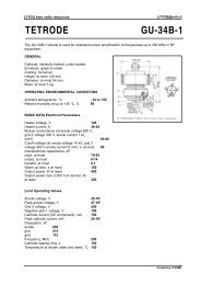
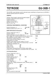
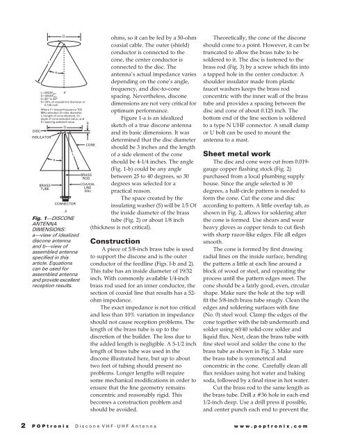
L=2953/F a<br />
MHz<br />
D=2008/FMHz<br />
θ=25º to 40º<br />
S=20% of coaxial line diameter or<br />
0.125 inch<br />
Where F=lowest frequency-700<br />
MHz selected, D=disc diameter,<br />
L=length of cone ellement, θ=<br />
angle of cone-selected value, and<br />
S=spacing-selected value<br />
S<br />
D<br />
DISC<br />
INSULATOR<br />
BRASS<br />
TUBE<br />
θ<br />
D<br />
L<br />
CONNECTOR<br />
b<br />
Fig. 1—DISCONE<br />
ANTENNA<br />
DIMENSIONS:<br />
a—view of idealized<br />
discone <strong>antenna</strong><br />
and b—view of<br />
assembled <strong>antenna</strong><br />
specified in this<br />
article. Equations<br />
can be used for<br />
assembled <strong>antenna</strong><br />
and provide excellent<br />
reception results.<br />
ohms, so it can be fed by a 50-ohm<br />
coaxial cable. The outer (shield)<br />
conductor is connected to the<br />
cone, the center conductor is<br />
connected to the disc. The<br />
<strong>antenna</strong>'s actual impedance varies<br />
depending on the cone's angle,<br />
frequency, and disc-to-cone<br />
spacing. Nevertheless, discone<br />
dimensions are not very critical for<br />
optimum performance.<br />
Figure 1-a is an idealized<br />
sketch of a true discone <strong>antenna</strong><br />
and its basic dimensions. It was<br />
determined that the disc diameter<br />
should be 3 inches and the length<br />
of a side element of the cone<br />
should be 4-1/4 inches. The angle<br />
(Fig. 1-b) could be any angle<br />
between 25 to 40 degrees, so 30<br />
degrees was selected for a<br />
practical reason.<br />
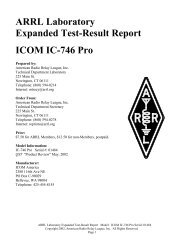
The space created by the<br />
insulating washer (S) will be 1/5 Of<br />
the inside diameter of the brass<br />
tube (Fig. 2) or about 1/8 inch<br />
(thickness is not critical).<br />
CONE<br />
BRASS<br />
ROD<br />
COAXIAL<br />
LINE<br />
50Ω<br />
Construction<br />
A piece of 5/8-inch brass tube is used<br />
to support the discone and is the outer<br />
conductor of the feedline (Figs. l-b and 2).<br />
This tube has an inside diameter of 19/32<br />
inch. With commonly available 1/4-inch<br />
brass rod used for an inner conductor, the<br />
section of coaxial line that results has a 52-<br />
ohm impedance.<br />
The exact impedance is not too critical<br />
and less than 10% variation in impedance<br />
should not cause reception problems. The<br />
length of the brass tube is up to the<br />
discretion of the builder. The loss due to<br />
the added length is negligible. A 5-1/2 inch<br />
length of brass tube was used in the<br />
discone illustrated here, but up to about<br />
two feet of tubing should present no<br />
problems. Longer lengths will require<br />
some mechanical modifications in order to<br />
ensure that the line geometry remains<br />
concentric and reasonably rigid. This<br />
becomes a construction problem and<br />
should be avoided.<br />
Theoretically, the cone of the discone<br />
should come to a point. However, it can be<br />
truncated to allow the brass tube to be<br />
soldered to it. The disc is fastened to the<br />
brass rod (Fig. 3) by a screw which fits into<br />
a tapped hole in the center conductor. A<br />
shoulder insulator made from plastic<br />
faucet washers keeps the brass rod<br />
concentric with the inner wall of the brass<br />
tube and provides a spacing between the<br />
disc and cone of about 0.125 inch. The<br />
bottom end of the line section is soldered<br />
to a type N <strong>UHF</strong> connector. A small clamp<br />
or U bolt can be used to mount the<br />
<strong>antenna</strong> to a mast.<br />
Sheet metal work<br />
The disc and cone were cut from 0.019-<br />
gauge copper flashing stock (Fig. 2)<br />
purchased from a local plumbing supply<br />
house. Since the angle selected is 30<br />
degrees, a half-circle pattern is needed to<br />
form the cone. Cut the cone and disc<br />
according to pattern. A little overlap tab, as<br />
shown in Fig. 2, allows for soldering after<br />
the cone is formed. Use shears and wear<br />
heavy gloves as copper tends to cut flesh<br />
with sharp razor-like edges. File all edges<br />
smooth.<br />
The cone is formed by first drawing<br />
radial lines on the inside surface, bending<br />
the pattern a little at each line around a<br />
block of wood or steel, and repeating the<br />
process until the pattern edges meet. The<br />
cone should be a fairly good, even, circular<br />
shape. Make sure the hole at the top will<br />
fit the 5/8-inch brass tube snugly. Clean the<br />
edges and soldering surfaces with fine<br />
(No. 0) steel wool. Clamp the edges of the<br />
cone together with the tab underneath and<br />
solder using 60/40 solid-core solder and<br />
liquid flux. Next, clean the brass tube with<br />
fine steel wool and solder the cone to the<br />
brass tube as shown in Fig. 3. Make sure<br />
the brass tube is symmetrical and<br />
concentric in the cone. Carefully clean all<br />
flux residues using hot water and baking<br />
soda, followed by a final rinse in hot water.<br />
Cut the brass rod to the same length as<br />
the brass tube. Drill a #36 hole in each end<br />
1/2-inch deep. Use a drill press if possible,<br />
and center punch each end to prevent the<br />
2<br />
POPtronix <strong>Discone</strong> <strong>VHF</strong>-<strong>UHF</strong> Antenna www.poptronix.com