fire pump controller - Metron Eledyne
fire pump controller - Metron Eledyne
fire pump controller - Metron Eledyne

Create successful ePaper yourself
Turn your PDF publications into a flip-book with our unique Google optimized e-Paper software.
SPECIALISTS IN FIRE PUMP CONTROL SY<br />
<strong>Eledyne</strong><br />
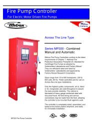
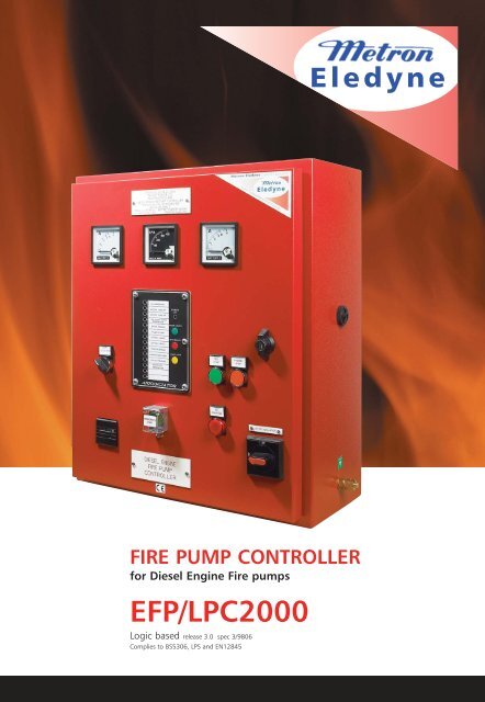
FIRE PUMP CONTROLLER<br />
for Diesel Engine Fire <strong>pump</strong>s<br />
EFP/LPC2000<br />
Logic based release 3.0 spec 3/9806<br />
Complies to BS5306, LPS and EN12845
FEATURES<br />
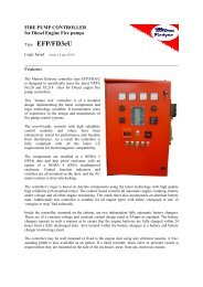
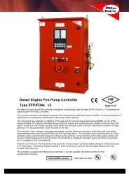
The <strong>Metron</strong> <strong>Eledyne</strong> Autostart type EFP/LPC/2000 Diesel Engine Fire Pump Controller is<br />
designed in accordance with the requirements of BS5306 part II and LPC regulations (Formerly<br />
FOC Rules- 29th Edition) for automatic and manual starting of diesel-driven <strong>fire</strong>water <strong>pump</strong>s<br />
for automatic sprinkler installations. There is also an option to upgrade this <strong>controller</strong> so that it<br />
meets the diesel engine standard LPS1239. (Option LPS). A simple software adjustment also<br />
means that this <strong>controller</strong> can fully comply to EN12845.<br />
Components are mainly mounted on a printed circuit board and modular for ease of<br />
maintenance. These are contained in a wall mounting, sheet steel, dust and drip-proof<br />
enclosure (IP51) with lock-up front access door. External wiring terminates at a clearly<br />
marked terminal rail.<br />
CONTROL SYSTEM<br />
‘Autostart’ operation powered by engine<br />
batteries only - independent of other<br />
sources of power and is initiated by<br />
sprinkler system low pressure as standard.<br />
Other initiating signals can also be<br />
accommodated.<br />
The <strong>controller</strong> is designed to provide up to six<br />
repeat 15 second cranks in a start cycle from<br />
the selected automatic battery, each crank<br />
separated by a dwell period of 10 seconds. In<br />
the event of the selected automatic battery<br />
set failing, the <strong>controller</strong> automatically selects<br />
the alternative battery set for the remaining<br />
cranks. If the engine fails to start after the<br />
sixth attempt, the <strong>controller</strong> will lock-out and<br />
initiate a failed to start alarm. Cranking is<br />
discontinued immediately following the<br />
detection of an engine run signal. An integral<br />
repeat start unit is provided, which<br />
disengages the crank solenoid momentarily if<br />
the starter fails to correctly engage under<br />
automatic start conditions.<br />
Manual Test Start facility (pushbutton<br />
initiated) is enabled after an automatic<br />
start, and indicates a visual warning<br />
indicator that manual test start is required.<br />
The manual test start and emergency<br />
manual start facilities are independent of<br />
the autostart test control system.<br />
No. Description Colour I.D.<br />
1 Battery 1 Ammeter A1<br />
3 Battery 2 Ammeter TAC<br />
5 Annunciator Module<br />
8 Test Start Push Button Green PB1<br />
9 Engine Hours Run Meter HR<br />
10 Emergency Start Push Button Green PB5<br />
11 AC/DC Isolator SW3<br />
12 DC Isolated Lamp Red L1<br />
Two independent fully-automatic battery<br />
chargers are incorporated, each with<br />
maximum output current limited to 5 or 10<br />
Amps with constant potential output at<br />
trickle charge to prevent battery gassing.<br />
Boost charge facility and charge rate<br />
ammeter are provided for each battery<br />
charger. Battery voltmeter and selector<br />
switch are available as an optional extra.<br />
Additional engine instrumentation gauges<br />
and monitoring systems are available as<br />
optional extras.
SPECIFICATIONS<br />
The door is lockable by use of the top door<br />
lock and AC isolator. The AC isolator is door<br />
interlocked and maybe be locked in the off<br />
position for maintenance purposes.<br />
The <strong>controller</strong> can be adjusted by software<br />
to comply with EN12845. The nature of the<br />
change relates to the crank sequence. In<br />
this mode, the auto crank cycle alternates<br />
the cranking battery from A to B after each<br />
crank attempt. The duty selector switch is<br />
not required for EN12845 versions.<br />
NEW LPS1239<br />
COMPLIANT<br />
The EFP/LPC2000 <strong>controller</strong> can now<br />
be upgraded so that it can be<br />
connected to a diesel engine which is<br />
approved to LPS1239.<br />
The upgrade includes: (See option<br />
‘LPS’ on the option list)<br />
• Isolated output for engine<br />
mounted tachometer<br />
• Protected engine jacket heater<br />
output, 1.5kW<br />
• Low Jacket temperature alarm &<br />
monitor<br />
• Engine stop solenoid output and<br />
push button<br />
Controller Status Signals<br />
Battery A healthy<br />
Battery B healthy<br />
Battery A boost charge on<br />
Battery B boost charge on<br />
Controller Alarm Signals<br />
Pump on demand<br />
Engine running<br />
Engine failed to start<br />
When lit, press test start<br />
Remote alarm signals (Volt free contacts)<br />
Pump on demand<br />
Engine running<br />
Engine failed to start<br />
D.C. battery supply failure<br />
Controls and instrumentation<br />
Combined A.C./D.C. supplies isolator<br />
(door-interlocked)<br />
Emergency manual start pushbutton<br />
(behind break glass flap)<br />
Manual start test pushbutton<br />
Alarm reset pushbutton<br />
Battery charger A ammeter<br />
Battery charger B ammeter<br />
Battery A/B automatic duty selector switch<br />
Engine hours run counter<br />
DC Isolated lamp<br />
Audible alarm<br />
ORDER CODE<br />
EFP 12V 120V LPC2000 OPTIONS<br />
24V<br />
230V<br />
When ordering, please specify; Engine manufacturer and model number.<br />
Engine start batteries, Lead-acid/Nickel cadmium, 12/24v, Ah capacity.<br />
A.C. mains supply, voltage & frequency.<br />
For speed switch option, number of teeth on engine flywheel & crank cut-off speed.<br />
Any optional extras required. EC ‘CE’ marking/certificate of conformity.<br />
003<br />
FM55714
SPECIALISTS IN FIRE PUMP CONTROL SY<br />
<strong>Metron</strong> <strong>Eledyne</strong> Ltd<br />
18 Autumn Park, Dysart Road, Grantham<br />
Lincolnshire NG31 7DD. United Kingdom<br />
Tel: +44 1476 516120<br />
Fax: +44 1476 516121<br />
Email: info@metroneledyne.co.uk<br />
Website: www.metroneledyne.co.uk<br />
<strong>Metron</strong> Inc<br />
1505 West Third Avenue<br />
Denver, CO 80223, United States of America<br />
Tel: +1 303 592 1903<br />
Fax: +1 303 534 1947<br />
<strong>Eledyne</strong><br />
DESCRIPTION OF OPTIONS<br />
8A<br />
10A<br />
A<br />
B1<br />
B2<br />
C<br />
D<br />
DG<br />
EN<br />
G1<br />
G2<br />
G3<br />
G4<br />
G<br />
8 Amp battery chargers.<br />
Standard battery charger, with manual boost facility<br />
10Amp battery charger.<br />
‘FM’ style automatic boost equalize float type. (Will require a larger than standard<br />
enclosure)<br />
Mains failure start<br />
Adjustable electronic timer which activates the automatic start sequence after the<br />
time delay is completed.<br />
Electronic speed switch (standard)<br />
Takes an electronic pulse from the engine and determines when the engine is<br />
running.<br />
Electronic speed switch (Fiat type)<br />
Same as B1, but for Fiat type engines.<br />
Auto stop timer<br />
Electronic adjustable timer to automatically stop the engine once <strong>pump</strong> on demand<br />
has cleared.<br />
Delay start timer (Sequence start)<br />
This is used to prevent the engine from starting upon a sudden pressure drop, thus<br />
ensuring that the engine is only started in a true low pressure situation. This option<br />
can also be used on multiple <strong>pump</strong> installations to prevent the <strong>pump</strong>s from starting<br />
simultaneously. It is accomplished by the use of an adjustable timer supplied in all<br />
<strong>controller</strong>s except the lead <strong>controller</strong>.<br />
Dual meter; Tachometer & voltmeter<br />
EN12845:2004<br />
When this option is selected the <strong>controller</strong> shall be designed to meet the<br />
requirements for EN12845:2004. A different crank cycle is enabled, and the duty<br />
selector switch is omitted.<br />
Engine oil pressure gauge<br />
Engine water temperature gauge<br />
Engine tachometer<br />
0 to 4000rpm door mounted instrument.<br />
Battery voltmeter and selector switch<br />
Anti-condensation heater<br />
When the <strong>controller</strong> is to be used in adversely low temperature conditions, this<br />
option will maintain a safe temperature for the <strong>controller</strong> to continue operating<br />
reliably.<br />
H1 Auxiliary channel 1<br />
Close to alarm multi-purpose alarm channel<br />
H2 Auxiliary channel 2<br />
LPS<br />
R1<br />
M<br />
S<br />
T1<br />
T3<br />
Y<br />
U1<br />
W<br />
See description on previous page<br />
AC Monitoring (Lamp and remote)<br />
Comprises of a mains on indicator, and a set of volt free contacts.<br />
Low oil pressure & High water temperature alarms<br />
Close to alarm engine monitoring channels, with a pre-set 10 second delay.<br />
Engine Stop timer<br />
Manually adjustable timer with door mounted push button. For engines fitted with<br />
an energise to stop solenoid.<br />
Mounting Lugs<br />
Plinth<br />
12 Channel expansion annunciator<br />
This option provides an extra 12 channel annunciator, with 8 additional volt free<br />
outputs.<br />
Pressure Switch<br />
Externally mounted adjustable pressure switch.<br />
IP65 Weather proof enclosure<br />
Website: www.metroninc.com