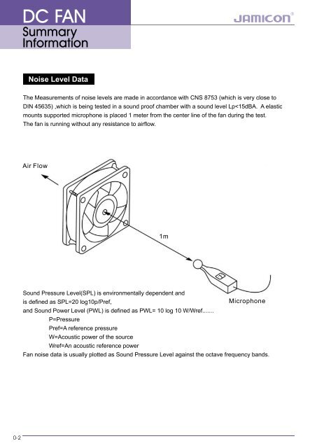
0-2 DC FAN Summary Information
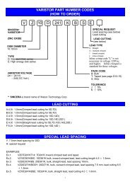
DC FAN Technical Information Part Number System JF 08 25 B 1 H M 00 1 -065 Internal control code Symbol code of the frame and impeller R could be 0~9, A~Z Environmental identification R: RoHS Detail wiring spec each character could be 0~9, A~Z or "-" could be 0~9 or A~Z <strong>Sp</strong>eed Voltage Bearing System V: Very low speed, E: Extra low speed, L: Low speed, M: Middle speed, H: High speed, S: Super High speed, U: Ultra High speed, T: Top High speed 1=12V, 2=24V, 3=32V, 4=48V, 5=5V, 6=60V, A=3V, B=25.5V, C=42V, D=18V, E=15V B: Dual ball bearing, C: Ball+Sleeve bearing, S: Sleeve bearing H: HTLS (High Temperature and Long life Sleeve bearing) Function –: Continuous code R: Auto-restart without signal output A: Alarm signal output with auto-restart M: Tachometer signal output with Auto-restart S: Tachometer signal output without auto-restart Y: IC temperature speed control with auto-restart U: IC temperature speed control with auto-restart and tachometer signal output V: IC temperature speed control with auto-restart and alarm signal output W: Economic temperature speed control with tachometer signal output P: PWM speed control Q: PWM speed control with alarm signal output K: PWM speed control with tachometer signal output Thickness of frame 06=6 mm, 07=7 mm, 10=10 mm, 12=12 mm, 15=15 mm, 20=20 mm, 25=25 mm, 28=28 mm, 32=32 mm, 38=38 mm, 51=51 mm Width of the frame 02=25 mm, 03=30 mm, 04=40 mm, 05=50 mm, 06=60 mm, 07=70 mm, 08=80 mm, 09=92 mm, 12=120 mm, 17=172 mm, 0A=20 mm, 0B=35 mm, 0C=45 mm Main Series Code JF or KF 1-1