Team XRay T1 Manual - Ashford Hobby
Team XRay T1 Manual - Ashford Hobby
Team XRay T1 Manual - Ashford Hobby

Create successful ePaper yourself
Turn your PDF publications into a flip-book with our unique Google optimized e-Paper software.
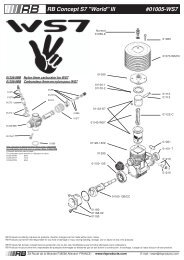
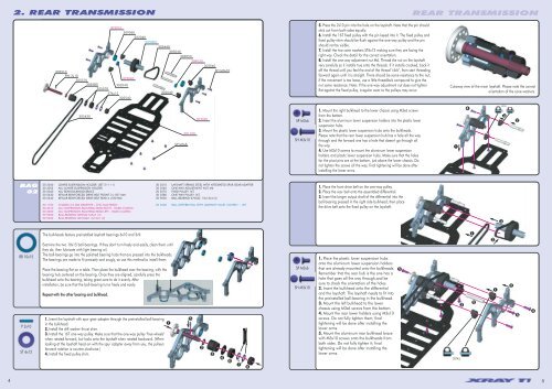
2. REAR TRANSMISSION<br />
REAR TRANSMISSION<br />
305510<br />
PIN 2x10<br />
305510<br />
305580<br />
305570<br />
303010<br />
309050<br />
302040<br />
305000<br />
305440<br />
303040<br />
302053<br />
309030<br />
302040<br />
SH M3x10<br />
302040<br />
309040<br />
ST6x12<br />
305540<br />
302040<br />
5. Press the 2x10 pin into the hole on the layshaft. Note that the pin should<br />
stick out from both sides equally.<br />
6. Install the 16T fixed pulley with the pin keyed into it. The fixed pulley and<br />
fixed pulley shim should be flush against the one-way pulley and the pin<br />
should not be visible.<br />
7. Install the two cone washers ST6x12 making sure they are facing the<br />
right way. Check the detail for the correct orientation.<br />
8. Install the one-way adjustment nut M6. Thread the nut on the layshaft<br />
very carefully so it installs true onto the threads. If it installs crooked, back it<br />
off the thread until you feel the end of the thread "click", then start threading<br />
forward again until it is straight. There should be some resistance to the nut;<br />
if the movement is too loose, use a little threadlock compound to give the<br />
nut some resistance. Note: If the one-way adjustment nut does not tighten<br />
flat against the fixed pulley, irregular wear to the pulleys may occur.<br />
Cutaway view of the main layshaft. Please note the correct<br />
orientation of the cone washers.<br />
305430<br />
SP M3x6<br />
301100<br />
303020<br />
SP M3x6<br />
SH M3x10<br />
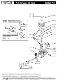
1. Mount the right bulkhead to the lower chassis using M3x6 screws<br />
from the bottom.<br />
2. Insert the aluminum lower suspension holders into the plastic lower<br />
suspension hubs.<br />
3. Mount the plastic lower suspension hubs onto the bulkheads.<br />
Please note that the rear lower suspension hub has a hole all the way<br />
through and the forward one has a hole that doesn't go through all<br />
the way.<br />
4. Use M3x10 screws to mount the aluminum lower suspension<br />
holders and plastic lower suspension hubs. Make sure that the holes<br />
for the pivot pins are at the bottom, just above the lower chassis. Do<br />
not tighten the screws all the way; final tightening will be done after<br />
installing the lower arms.<br />
➊<br />
➍<br />
DETAIL<br />
➌<br />
➋<br />
BAG<br />
02<br />
30 2040 LOWER SUSPENSION HOLDER (SET 2+1+1)<br />
30 2053 ALU LOWER SUSPENSION HOLDER<br />
30 3040 ALU REAR BULKHEAD BRACE<br />
30 5430 KEVLAR REINFORCED DRIVE BELT FRONT 3 x 507 MM<br />
30 5440 KEVLAR REINFORCED DRIVE BELT REAR 4 x180 MM<br />
30 1100 CHASSIS 2.5 MM GRAPHITE - CNC MACHINED<br />
30 3010 ALU SUSPENSION BULKHEAD REAR RIGHT - HARD COATED<br />
30 3020 ALU SUSPENSION BULKHEAD REAR LEFT - HARD COATED<br />
30 9030 BALL-BEARING MR95ZZ 5x9x3 (2)<br />
30 9040 BALL-BEARING MR106ZZ 6x10x3 (2)<br />
30 5510 LAYSHAFT SPRING STEEL WITH NTEGRATED SPUR GEAR ADAPTER<br />
30 5540 ONE-WAY ADJUSTMENT NUT M6<br />
30 5570 FIXED PULLEY 16T<br />
30 5580 ONE WAY PULLEY 16T<br />
30 9050 BALL-BEARING 6700ZZ 10x15x4 (2)<br />
30 5000 BALL DIFFERENTIAL WITH LABYRINTH DUST COVERS - SET<br />
1. Place the front drive belt on the one-way pulley.<br />
2. Place the rear belt onto the assembled differential.<br />
3. Insert the longer output shaft of the differential into the<br />
ball-bearing pressed in the right side bulkhead, then place<br />
the drive belt onto the fixed pulley on the layshaft.<br />
➌<br />
BB 10x15<br />
P 2x10<br />
ST 6x12<br />
The bulkheads feature preinstalled layshaft bearings 6x10 and 5x9.<br />
Examine the two 10x15 ball-bearings. If they don't turn freely and easily, clean them until<br />
they do, then lubricate with light bearing oil.<br />
The ball-bearings go into the polished bearing hubs that are pressed into the bulkheads.<br />
The bearings are made to fit precisely and snugly, so use this method to install them:<br />
Place the bearing flat on a table. Then place the bulkhead over the bearing, with the<br />
bearing hub centered on the bearing. Once they are aligned, carefully press the<br />
bulkhead onto the bearing, taking great care to do it evenly. After<br />
installation, be sure that the ball-bearing turns freely and easily.<br />
Repeat with the other bearing and bulkhead.<br />
1. Insert the layshaft with spur gear adapter through the preinstalled ball-bearing<br />
in the bulkhead.<br />
➊<br />
2. Install the diff washer thrust shim.<br />
3. Install the 16T one-way pulley. Make sure that the one-way pulley "free wheels"<br />
when rotated forward, but locks onto the layshaft when rotated backward. (When<br />
looking at the layshaft head-on with the spur adapter away from you, the pulley's<br />
forward rotation is counter-clockwise.)<br />
4. Install the fixed pulley shim.<br />
➎<br />
➋<br />
➌<br />
➍<br />
SP M3x6<br />
SH M3x10<br />
1. Place the plastic lower suspension hubs<br />
onto the aluminum lower suspension holders<br />
that are already mounted onto the bulkheads.<br />
Remember that the rear hub is the one has a<br />
hole that goes all the way through,and be<br />
sure to check the orientation of the holes.<br />
2. Insert the bulkhead onto the differential<br />
and the layshaft. The layshaft needs to fit into<br />
the preinstalled ball-bearing in the bulkhead.<br />
3. Mount the left bulkhead to the lower<br />
chassis using M3x6 screws from the bottom.<br />
4. Mount the rear lower holders using M3x10<br />
screws. Do not fully tighten them; final<br />
tightening will be done after installing the<br />
lower arms.<br />
5. Mount the aluminum rear bulkhead brace<br />
with M3x10 screws onto the bulkheads from<br />
both sides. Do not fully tighten it; final<br />
tightening will be done after installing the<br />
lower arms.<br />
➎<br />
DETAIL<br />
➌<br />
➊<br />
➎<br />
➋<br />
➊<br />
➋<br />
➎<br />
➍<br />
➏ ➐ ➑<br />
4<br />
5