Specifications
Specifications
Specifications

You also want an ePaper? Increase the reach of your titles
YUMPU automatically turns print PDFs into web optimized ePapers that Google loves.
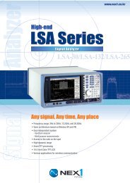
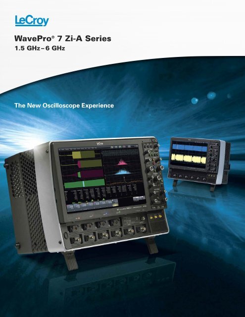
WavePro ® 7 Zi-A Series<br />
1.5 GHz–6 GHz<br />
The New Oscilloscope Experience
THE NEW OSCILLOSCOPE EXPERIENCE IS THE NEW OSCILLOSCOPE EXPERIENCE IS HERE HERE<br />
7<br />
The Only Complete Debug<br />
Solution Up to 6 GHz<br />
Combining signal fidelity with an<br />
architecture that maximizes speed in<br />
every performance aspect, the new<br />
WavePro 7 Zi-A Series presents a totally<br />
new oscilloscope experience from<br />
1.5 to 6 GHz bandwidths. Experience<br />
50 Ω and 1 MΩ inputs for every channel<br />
and four inputs into high-speed front end<br />
amplifiers and analog to digital converters.<br />
6<br />
4<br />
1<br />
2<br />
The X-Stream II architecture maximizes<br />
speed in all aspects—10–100 times faster<br />
analysis processing on maximum record<br />
lengths, instantaneous instrument responsiveness,<br />
and 20 times faster off-line data<br />
transfer. Combined with LeCroy’s flexible and<br />
deep analysis toolbox, the WavePro 7 Zi-A<br />
Series provides superior performance for the<br />
debugging, validation, compliance testing,<br />
and analysis of electronic designs.<br />
13<br />
14<br />
2
11<br />
1. X-Stream II streaming architecture—10–100 times<br />
faster than other oscilloscopes<br />
2. Deepest toolbox with more measurements,<br />
more math, more power<br />
5<br />
3. TriggerScan detects and captures more<br />
anomalies per second<br />
4. Exceptional instrument responsiveness, even<br />
at maximum acquisition memory (256 Mpts)<br />
12<br />
5. 325 MB/s data transfer rate from oscilloscope to<br />
PC with LeCroy Serial Interface Bus (LSIB) option<br />
3<br />
8<br />
9<br />
6. 750,000 measurements/second with optimal<br />
signal integrity<br />
7. 15.3" widescreen (16x9) high resolution<br />
WXGA color touch screen display<br />
8. Protect your investment with bandwidth upgrades<br />
9. Serial Data Analyzer and Disk Drive Analyzer<br />
models are tailored for advanced serial data<br />
analysis and for the most complete disk drive<br />
test solution<br />
10. PCI Express ® Gen 1.x, and 2.0 transaction<br />
layer (protocol and BitTracer view), link layer,<br />
and 8b/10b decode<br />
11. Largest selection of serial triggers and decoders<br />
—more than 14—available to provide a total<br />
system view<br />
12. WaveScan quickly and intuitively locates,<br />
analyzes and displays abnormal events even<br />
in long waveforms<br />
13. 50 Ω and 1 MΩ inputs with both ProBus and ProLink<br />
probe interfaces on all models provide support<br />
for every probe manufactured by LeCroy without<br />
requiring external adapters or probe amplifiers<br />
14. ProBus and ProLink probe interfaces on 4–6 GHz<br />
models offer 8 inputs for multiplexing into four<br />
channels. Minimize reconnections.<br />
3
MOST COMPLETE DEBUG SOLUTION FROM 1.5–6 MOST COMPLETE DEBUG SOLUTION FROM 1.5–6 GHZ GHz<br />
Freedom from Limitations<br />
WavePro 7 Zi-A excels in the way it<br />
offers general purpose utility never<br />
before seen in oscilloscopes from<br />
1.5 to 6 GHz. All WavePro 7 Zi-A oscilloscopes<br />
contain selectable 50 Ω and<br />
1 MΩ input capability. The 4 and<br />
6 GHz models include both ProBus<br />
and ProLink input types which means<br />
eight probes can be attached and then<br />
4<br />
multiplexed from the front panel<br />
or by remote control. The result—<br />
it’s easy to hook up a passive probe<br />
even on 4 or 6 GHz models—no<br />
more frustration and hassle of trying<br />
to find a 1 MΩ input adapter. Plus,<br />
any existing investment in LeCroy<br />
probes, such as current probes,<br />
single-ended or differential active<br />
probes, or high voltage probes, is<br />
fully leveraged. Perfect.<br />
A New Way to Control an<br />
Oscilloscope<br />
WavePro’s fast and responsive<br />
front panel and touch screen user<br />
interface are well integrated so you<br />
can easily choose and setup your<br />
vertical, horizontal trigger and measurements.<br />
Zoom and scroll through<br />
a long waveform signal, control the<br />
oscilloscope with the detachable<br />
front panel right next to the circuit<br />
being probed.
Quick Insight for Debug<br />
Insight is the power or act of seeing into a situation.<br />
Start up problems on a new design require a combination<br />
of problem recognition, precise triggering for fast<br />
isolation of rare events, and comparison tools that help<br />
correlate timing of problems. The ability to capture<br />
megapoints of waveform information and intuitively<br />
analyze it to find anomalies shortens the time to<br />
debug. WavePro’s TriggerScan, WaveScan and deep<br />
measurement toolbox maximize quick insight.<br />
Single-ended active probes, current<br />
probes, high-voltage, mixed signals,<br />
and high frequency differential probes<br />
all connect to the WavePro 7 Zi-A<br />
oscilloscope and give you a total<br />
system view.<br />
5
MOST COMPLETE DEBUG SOLUTION FROM 1.5–6 MOST COMPLETE DEBUG SOLUTION FROM 1.5–6 GHz GHz<br />
6<br />
Complete System Debug<br />
Understanding the relationships<br />
between different signals is vital<br />
to fast debug. Only WavePro 7 Zi-A<br />
combines the best of general<br />
purpose oscilloscopes (low-speed<br />
serial triggers and decoders, mixed<br />
signal capability, high impedance<br />
probing) to allow easy correlation<br />
between low-speed (serial data<br />
control words, power supply<br />
noise, or parallel data transmissions)<br />
and high speed events.<br />
Get more insight with multiple<br />
views of your serial data<br />
transmissions.<br />
More Trigger Capability Isolates<br />
More Problems More Quickly<br />
A powerful combination of high bandwidth<br />
Edge and 10 different SMART triggers, fourstage<br />
Cascade triggering, and TriggerScan<br />
are all standard and allow you to isolate the<br />
problem quickly and begin to focus on the<br />
cause. A high-speed serial trigger enables<br />
triggering on up to 3.125 Gb/s serial patterns<br />
of up to 80-bits in length. A full range of<br />
protocol serial triggers (I 2 C, SPI, UART,<br />
RS-232, Audiobus (I 2 S, LJ, RJ, TDM), CAN,<br />
LIN, FlexRay, MIL-STD-1553 and many others)<br />
are also available.<br />
Capture 5 ms (100 Mpts) of low-speed and<br />
high-speed waveforms. Decode low and high<br />
speed serial data signals. Easily zoom, and<br />
validate timing relationships between signals.<br />
Serial Decode—A Whole<br />
New Meaning to Insight<br />
Over 14 different protocols are supported<br />
with serial decoders (many with hardware<br />
protocol triggers as well). Use ProtoSync to<br />
get a dual-display view of both oscilloscopegenerated<br />
decode annotations and protocol<br />
analyzer software views. Search on protocol<br />
data in a table and export table data to an<br />
Excel file.<br />
Learn More http://www.lecroy.com/dl/3005<br />
UART<br />
I 2 C<br />
A<br />
B<br />
SPI<br />
LIN<br />
FlexRay<br />
Search and Scan to<br />
Understand<br />
Search a captured waveform for<br />
hundreds of different measurement<br />
parameters or other conditions using<br />
WaveScan. Set complex conditions,<br />
view search results on the waveform<br />
and in a table, and quickly zoom and<br />
jump to an entry. “Scan” for events<br />
that can’t be triggered in hardware.<br />
Freedom from Probing<br />
Limitations<br />
High bandwidth differential probes<br />
(up to 6 GHz), single-ended active<br />
probes, current probes, high-voltage,<br />
and mixed signals all connect to the<br />
WavePro 7 Zi-A oscilloscope and<br />
give you a total system view. All<br />
WavePro 7 Zi-A oscilloscopes contain<br />
selectable 50 Ω and 1 MΩ input<br />
capability and can be used with any<br />
LeCroy probe—passive or active—<br />
without requiring external adapters<br />
or power supplies.<br />
Fully Integrated Mixed Signal<br />
Oscilloscope (4+36) Option<br />
Add Mixed Signal Oscilloscope (MSO)<br />
operation using the MS Series mixed<br />
signal options to acquire up to 36 digital<br />
lines time-correlated with analog waveforms<br />
and completely integrated with<br />
the scope operation. In addition to<br />
acquiring digital lines, they are also<br />
helpful for monitoring low-speed<br />
signals, such as serial data clock, data,<br />
and chip select signals, thus preserving<br />
the analog channels for higher speed<br />
requirements.
X-STREAM II FAST ANALYSIS AND X-STREAM II FAST ANALYSIS AND RESPONSIVENESS<br />
RESPONSIVENESS<br />
Deep Insight<br />
for Analysis<br />
Applying the WavePro 7 Zi-A<br />
Series’ flexible and deep<br />
measurement and analysis<br />
toolbox to characterize<br />
and validate a design<br />
creates understanding.<br />
That is Deep Insight.<br />
An oscilloscope’s operating<br />
performance comes<br />
from the design that<br />
integrates the operating<br />
system, the hardware<br />
processor specification<br />
and the waveform processing<br />
method. Each<br />
component is important<br />
to the overall architecture<br />
performance but only<br />
the X-Stream II waveform<br />
processing method unleashes<br />
amazing speed<br />
performance and no compromise<br />
in responsiveness,<br />
thus drastically reducing<br />
the time to generate<br />
Deep Insight.<br />
7
LeCroy—The Analysis<br />
Memory Leader<br />
LeCroy has found a way to make long<br />
acquisition memory seamless and pain<br />
free to use. The WavePro 7 Zi-A Series’<br />
proprietary X-Stream II architecture<br />
supports capturing, zooming, measuring<br />
and analyzing multiple waveforms at up<br />
to 256 Mpts deep. WavePro 7 Zi-A’s<br />
proprietary architecture design is<br />
augmented with an Intel ® Core 2<br />
Quad processor (12 GHz effective clock<br />
rate), high-speed serial data buses,<br />
Windows 7 64-bit OS and 8 GB of<br />
RAM. What you experience is<br />
processing speed 10–100x faster<br />
compared to other oscilloscopes in<br />
this class.<br />
Instantaneous Responsiveness<br />
With WavePro 7 Zi-A oscilloscopes<br />
you will experience remarkable<br />
responsiveness. Acquiring and<br />
manipulating the longest record lengths<br />
and performing the most complex<br />
WaveShape Analysis are all easily<br />
WavePro 7 Zi-A excels at performing complex calculations on long waveforms, enabling<br />
users to gain waveform insight with confidence. Here, a 40 Mpts PCIe Gen1 waveform<br />
acquisition is acquired and fully analyzed in a matter of seconds—nearly 100x faster than<br />
competitive oscilloscopes.<br />
handled at the same time, unlike<br />
competitive oscilloscopes that<br />
become painfully slow to respond<br />
when long memory is applied.<br />
Bottom line: oscilloscopes no longer<br />
need to carry a penalty for operating<br />
with long memory.<br />
Fast Off-line Data Transfer<br />
When the application calls for postprocessing<br />
data off-line, an optional<br />
LeCroy Serial Interface Bus (LSIB)<br />
high-speed 325 MB/s option provides<br />
data transfer 20–100x faster than any<br />
other test instrument. For remote<br />
control, WavePro 7 Zi-A is Class C<br />
compliant with the LXI standard, the<br />
latest industry standard for Ethernet<br />
remote control operation. WavePro 7<br />
Zi-A supports standard LXI features<br />
such as a LAN interface, VXI11<br />
Discovery, a web server and IVI-C &<br />
IVI-COM drivers.<br />
X-Stream II Architecture<br />
Optimized for Fast Throughput<br />
X-Stream II architecture enables high<br />
throughput of data—even when the oscilloscope<br />
is performing multiple 100 Mpts (or<br />
larger) waveforms. X-Stream II uses variable<br />
waveform segment lengths to enable all<br />
processing intensive calculations to take<br />
place in fast CPU cache memory, thus<br />
improving calculation speed and efficiency.<br />
The result—10–100x faster processing<br />
compared to other oscilloscopes.<br />
Learn More<br />
http://www.lecroy.com/dl/5213<br />
Optimized for Long Memory<br />
X-Stream II has no analysis memory length<br />
restrictions, regardless of analysis type,<br />
since the variable waveform segment<br />
length can always be limited to a size<br />
that can fit in CPU cache memory. Other<br />
oscilloscopes with conventional architectures<br />
cannot make this claim, and often<br />
have limitations on analysis memory of<br />
5–20% the length of their acquisition<br />
memory under the best conditions.<br />
Optimized for Responsiveness<br />
By dynamically allocating buffers to maximize<br />
memory availability, the WavePro 7<br />
Zi-A Series embodies the fastest front<br />
panel responsiveness. Oscilloscopes from<br />
other manufacturers can suffer from<br />
annoying delays during simple zoom<br />
operations, but not WavePro 7 Zi-A.<br />
Learn More<br />
http://www.lecroy.com/dl/5214<br />
8
DEEP INSIGHT CLARIFIES COMPLEX DEEP INSIGHT CLARIFIES COMPLEX SIGNALS SIGNALS<br />
All Oscilloscope Tools are<br />
not Created Equal<br />
WavePro 7 Zi-A has the deepest<br />
toolbox of any oscilloscope, providing<br />
more measure, math, graphing,<br />
statistical, and other tools, and more<br />
ways to leverage the tools to get the<br />
answer faster. While many other<br />
oscilloscopes provide similar looking<br />
tools, LeCroy allows the most flexibility<br />
in applying the tools to any<br />
waveform.<br />
Customized Tools<br />
Only LeCroy completely integrates<br />
third party programs into the scope’s<br />
processing stream by allowing you to<br />
create and deploy a new measurement<br />
or math algorithm directly into<br />
the oscilloscope environment and<br />
display the result on the oscilloscope<br />
in real-time! There is no need to run<br />
a separate program, or ever leave<br />
the oscilloscope window. Use<br />
C/C++, MATLAB, Excel, Jscript<br />
(JAVA), and Visual Basic to create<br />
your own customized math functions,<br />
measurement parameters, or<br />
other control algorithms.<br />
Graphical Track, Trend, and<br />
Histogram Views<br />
Track plots measurement values<br />
on the Y-axis and time on the X-axis<br />
to display a measurement change<br />
time-correlated to the original<br />
channel acquisition—perfect for<br />
intuitive understanding of behaviors<br />
in frequency modulated (FM) or<br />
pulse width modulated (PWM)<br />
X-Stream II fast throughput streaming architecture makes difficult analysis and deep<br />
insight possible. Above, an FFT is applied to a 50 Mpts waveform to determine root<br />
cause failure. The high frequency resolution this provides enables deep insight into<br />
signal pathologies.<br />
XDEV Customization software package being used to implement a<br />
1 MHz Butterworth filter using MATLAB ® .<br />
circuits and jitter measurements,<br />
including modulation or spikes.<br />
Histograms provide a visual<br />
distribution representation of a<br />
large sample of measurements,<br />
allowing faster insight. Trends are<br />
ideal for plotting slow changes in<br />
measurement values.<br />
Capture a single clock channel (yellow) and<br />
display Track graphs and Histograms<br />
simultaneously of multiple jitter parameters.<br />
9
PROBES PROBES<br />
High-performance probes are an essential tool for accurate signal capture. Consequently<br />
LeCroy offers an extensive range of probes to meet virtually every application need. Optimized<br />
for use with LeCroy oscilloscopes, these probes set new standards for responsiveness and<br />
signal detection.<br />
ZS Series High Impedance<br />
Active Probes<br />
• 1 GHz (ZS1000),1.5 GHz (ZS1500)<br />
and 2.5 GHz (ZS2500) bandwidths<br />
• High Impedance (0.9 pF, 1 MΩ)<br />
• Extensive standard and available<br />
probe tip and ground connection<br />
accessories<br />
• ±12 Vdc offset<br />
(ZS1500)<br />
• LeCroy<br />
ProBus<br />
system<br />
PPE1.2KV, PPE2KV, PPE4KV,<br />
PPE5KV, PPE6KV, PPE20KV<br />
• Suitable for safe, accurate<br />
high-voltage measurements<br />
• 1.2 kV to 20 kV<br />
• Works with any 1 MΩ input<br />
oscilloscope<br />
ZD500, ZD1000, and ZD1500<br />
• 500 MHz, 1 GHz, , and 1.5 GHz<br />
bandwidths<br />
• Wide dynamic range, low noise<br />
• LeCroy ProBus System<br />
ADP305, ADP300<br />
• 20 MHz and 100 MHz bandwidth<br />
• 1,000 V rms common mode voltage<br />
• 1,400 V peak differential voltage<br />
• EN 61010 CAT III<br />
• 80 dB CMRR at 50/60 Hz<br />
• LeCroy ProBus<br />
system<br />
CP030 and CP031<br />
• 30 A rms continuous current<br />
• 50 or 100 MHz bandwidth<br />
• Measure pulses up to 50 A peak<br />
• Small form factor accommodates<br />
large conductors with small<br />
jaw size<br />
• LeCroy ProBus<br />
system<br />
ZD200<br />
• 200 MHz bandwidth<br />
• 3.5 pF, 1 MΩ<br />
• Wide dynamic and common<br />
mode range<br />
• LeCroy ProBus System<br />
• Ideal for serial data and automotive<br />
applications<br />
10
WAVELINK WAVELINK PROBES PROBES<br />
D610/D620 and D410/D420<br />
The D610/D620 and D410/D420 probes<br />
boast excellent noise performance that<br />
is essential for making precise jitter and<br />
other signal integrity measurements. The<br />
high DC and midband impedance make<br />
them ideal for many serial data and memory<br />
applications such as PCI Express, FireWire,<br />
and DDR. With ±4 volt offset capability<br />
and ±3 volt common mode control, the<br />
WaveLink probes are designed for multipurpose<br />
applications for single-ended<br />
needs (such as DDR memory) and serial<br />
data applications (such as HDMI).<br />
The WaveLink Differential Probe Series is a high bandwidth active differential<br />
probes series. These probes are suited for signal integrity measurements in<br />
high-speed digital systems.<br />
D600A-AT/D500PT Browser<br />
WaveLink browser solutions offer<br />
adjustable tip widths and varying form<br />
factors and a hand held x-y-z positioner<br />
for accurate probe placement.<br />
Five Different Tips for Interconnect Flexibility<br />
A. Solder-In<br />
Lead (SI)<br />
The Solder-In interconnect<br />
lead features the<br />
smallest physical tip<br />
size of any high bandwidth<br />
differential probe<br />
and the highest level of<br />
electrical performance.<br />
B. Quick Connect<br />
(QC) (D6xx only)<br />
The Quick Connect interconnect<br />
lead enables<br />
you to quickly move the<br />
probe between multiple<br />
test points on the test<br />
circuit.<br />
C. Square Pin (SP)<br />
Many applications, such<br />
as IC characterization<br />
boards, use standard<br />
0.025" square pins for<br />
interconnect. The Square<br />
Pin interconnect lead<br />
directly mates with a<br />
pair of 0.025" (0.635 mm)<br />
square pins that are<br />
mounted on standard<br />
D. Positioner Tip (PT)<br />
The PT positioner tips<br />
provides spring loaded<br />
leads to allow for easy<br />
probing. The adjustable<br />
wheel allows for precise<br />
probing, allowing a<br />
spread up to 0.14".<br />
E. High Temperature<br />
(HiTemp) Cables and<br />
Solder-In Lead<br />
The 90 cm HiTemp cables<br />
and Solder-In lead is<br />
ideally suited for testing<br />
scenarios there the<br />
temperature can fluctuate<br />
from -40C to +105C.<br />
0.100" (2.54 mm) centers.<br />
11
APPLICATION SPECIFIC APPLICATION SPECIFIC SOLUTIONS<br />
SOLUTIONS<br />
In addition to the general purpose WaveShape Analysis tools, application specific solutions are<br />
available for Serial Data Compliance, Embedded Design, Digital Design, and Automotive. These<br />
packages extend the LeCroy standard measurement and analysis capabilities and expand your<br />
oscilloscope’s utility as your needs change.<br />
Data Transfer Speeds<br />
up to 325 MB/s<br />
LeCroy’s Serial Interface Bus (LSIB)<br />
option enables direct connection to<br />
the PCI Express ® x4 high-speed data<br />
bus in the oscilloscope to enable<br />
data transfer rates up to 325 MB/s—<br />
20–100x faster than other methods.<br />
All that is required is installation of an<br />
optional LSIB card in the oscilloscope<br />
and the corresponding host board<br />
(card) for desktop (laptop) PC in the<br />
remote computer. Data transfer is<br />
easily enabled through a supplied<br />
application program interface (API).<br />
Synchronize Two<br />
Oscilloscopes (Zi-8CH-SYNCH)<br />
Quickly and easily combine two<br />
oscilloscope acquisition systems into<br />
one with captured waveformson a<br />
single display for intuitive debug<br />
and analysis. Up to 8 channels at<br />
6 GHz may be captured using the<br />
Zi-8CH-SYNCH and two 7 Zi-A scopes.<br />
Spectrum Analyzer Analysis<br />
Package (WPZi-SPECTRUM)<br />
SPECTRUM converts the controls of<br />
your oscilloscope to those of a spectrum<br />
analyzer. Adjust the frequency span,<br />
resolution and center frequency. Apply<br />
filtering to your signal and watch the<br />
frequency signature change in real<br />
time. A unique peak search<br />
labels spectral components<br />
and presents<br />
frequency and level in<br />
a table. Touch any line to<br />
move to that peak.<br />
12<br />
Double The Display Area<br />
The integrated second touchscreen<br />
display (Zi-EXTDISP-15) is ideal for<br />
debug as it allows many simultaneous<br />
views.<br />
ProtoSync Solutions<br />
ProtoSync links physical layer<br />
waveforms, data link layer decode<br />
annotation and table information, and<br />
full transaction layer protocol analysis<br />
together. By simply touching a<br />
decode table entry in the oscilloscope<br />
software or a packet in the protocol<br />
analysis software, all views are automatically<br />
synchronized and aligned for<br />
quick and easy debug.<br />
Digital Filter Software<br />
Package (WP7Zi-DFP2)<br />
Create and apply a variety of FIR<br />
and IIR digital filters to your capture<br />
waveforms or processed traces.
Mixed Signal Oscilloscope<br />
Option (MS-250/MS-500)<br />
The Mixed Signal option allows<br />
the WavePro 7 Zi-A to convert to a<br />
mixed signal oscilloscope with up<br />
to 36 digital channels. Channels are<br />
sampled at 2 GS/s (500 MHz max.<br />
clock speed) up to 50 Mpts/Ch.<br />
Having up to 36 digital inputs<br />
time-synchronized with four analog<br />
channels extends the oscilloscope’s<br />
use to provide a total system view.<br />
Serial Data Trigger/Decode<br />
and PROTObus MAG Serial<br />
Debug Toolkit<br />
More than 14 trigger and decode<br />
options provide powerful conditional<br />
serial data protocol triggering, intuitive<br />
color-coded decode overlays, and a<br />
table summary with search and zoom<br />
capabilities. Additionally, PROTObus<br />
MAG (measure, analysis, graph)<br />
Serial Debug Toolkit provides the ability<br />
to quickly validate and analyze serial<br />
data cause-effect relationships and<br />
plot digitally encoded data as an<br />
analog waveform.<br />
Eye Doctor II—Advanced<br />
Signal Integrity Tools<br />
(WP7Zi-EYEDRII)<br />
Eye Doctor II Signal Integrity Tools<br />
provide the ability to add precision to<br />
signal integrity measurements by<br />
allowing subtraction of fixture effects<br />
and emulation of emphasis, serial data<br />
channels and provide for receiver equalization.<br />
Advanced modes for true virtual<br />
probing are also provided.<br />
Learn More<br />
http://www.lecroy.com/dl/1023<br />
http://www.lecroy.com/vid/M0T6WEC0JYQ<br />
http://www.lecroy.com/dl/1216<br />
http://www.lecroy.com/dl/1136<br />
Serial Data Compliance Packages<br />
QualiPHY serial data compliance packages provide easy to use<br />
step-by-step instructions for a broad set of serial data standards,<br />
such as USB 2.0, PCI Express, SATA, and UWB (Ultra-Wideband).<br />
With fast automated performance, illustrated instructions and<br />
comprehensive reporting capability, QualiPHY packages are the<br />
best solution for compliance testing.<br />
For standards not supported with QualiPHY compliance packages,<br />
jitter and eye diagram test toolsets are generally included in the<br />
SDA 7 Zi-A models.<br />
13
SDA 7 Zi-A SDA 7 Zi-A SERIES SERIES<br />
Key Features<br />
• LeCroy’s unique summary<br />
view displays the Eye<br />
Pattern, TIE, Bathtub Curve<br />
and Jitter Histogram all on<br />
the screen at the same time<br />
14<br />
• De-embed cables allow all<br />
of the SDA tools to be used<br />
as if the cables were not in<br />
the system<br />
• Create Eye Patterns utilizing<br />
the full memory for maximum<br />
statistical significance<br />
• Display Eye Patterns up<br />
to 100 times faster than<br />
other solutions<br />
• Trigger on 80-bit patterns<br />
at up to 3.125 Gb/s using the<br />
Serial Trigger<br />
• Decode 8b/10b data on up<br />
to 4 lanes simultaneously<br />
• Configure software PLL<br />
for any standard or custom<br />
requirement<br />
• Serial data compliance testing<br />
– 10/100/1000 BaseT ENET<br />
– USB 2.0<br />
– MIPI D-PHY<br />
– DDR2 / DDR3<br />
– PCI Express<br />
– DisplayPort<br />
– SAS<br />
– HDMI<br />
– UWB<br />
– SATA<br />
Versatile SDA II for Compliance<br />
and Debug<br />
For compliance testing, LeCroy’s<br />
QualiPHY compliance test suite<br />
provides the best available solutions<br />
to automate, configure and document<br />
standardized tests. However, when<br />
a design fails a compliance test,<br />
advanced toolsets are required for<br />
problem solving. The LeCroy SDA 7 Zi-A<br />
includes a debugging toolset with<br />
insight into eye and jitter analysis.<br />
Armed with this insight, engineers<br />
can confidently drill down and identify<br />
the root cause. The Quick View of the<br />
SDA II shows the eye diagram, TIE<br />
track, bathtub curve, jitter histogram,<br />
NQ-scale, and jitter spectrum. No<br />
other analyzer provides simultaneous<br />
interaction and real-time changes<br />
in all six measurements. LeCroy’s<br />
X-Stream II Architecture provides fast<br />
updates and the fastest eye interpretation.<br />
The fastest eye building and<br />
maximum unit intervals per second<br />
means finding solutions faster.<br />
A high-speed serial trigger enables<br />
triggering on up to 3.125 Gb/s serial<br />
patterns (up to 80-bits in length),<br />
allowing up to two 8b/10b primitives<br />
to be triggered. With the most<br />
advanced long memory performance<br />
(256 Mpts/Ch and X-Stream II enabled<br />
responsiveness), eye and jitter analysis<br />
occurs rapidly.
A TOTAL SOLUTION FOR SERIAL DATA A TOTAL SOLUTION FOR SERIAL DATA ANALYSIS ANALYSIS<br />
Automated Compliance<br />
Testing<br />
The QualiPHY compliance test suite<br />
provides step-by-step instructions for<br />
testing compliance on a wide array<br />
of serial data standards. The process<br />
is simplified with fast, automated test<br />
operations, illustrated instructions,<br />
connection diagrams, and stop-on-fail<br />
feature. Complete test reporting is<br />
also provided.<br />
Whether debugging eye pattern or<br />
other compliance test failures, the<br />
SDA 7 Zi-A Series rapidly isolates the<br />
source of the problem in your design.<br />
Advanced usability like 8b/10b<br />
decode, mask violation locator, ISI<br />
plot, and equalization are easy to find.<br />
Provide cable characteristics and<br />
Cable De-embedding automatically<br />
adjusts for the cable effects. The<br />
result—true rise time and amplitudes<br />
in measurements. The SDA II uses<br />
the same flexible math on math<br />
analysis, which is valuable when<br />
understanding design behavior<br />
during compliance failures.<br />
Standard<br />
Ethernet<br />
USB<br />
Fibre Channel<br />
IEEE 1394b FireWire<br />
Rapid I/O LP-LVDS<br />
Fibre Channel<br />
IOF<br />
Ethernet<br />
Rapid I/O LP-LVDS<br />
Rapid I/O LP-LVDS<br />
MIPI D-PHY<br />
SAS<br />
SerialATA<br />
IEEE 1394b FireWire<br />
HDMI 1.2a / DVI<br />
Rapid I/O LP-LVDS<br />
Fibre Channel<br />
InfiniBand<br />
PCI Express<br />
Rapid I/O LP-LVDS<br />
Data Rate Configuration Chart<br />
Bit Rate<br />
250 Mb/s<br />
480 Mb/s<br />
531.25 Mb/s<br />
786.43 Mb/s<br />
1 Gb/s<br />
1.0625 Gb/s<br />
1.24416 Gb/s<br />
1.25 Gb/s<br />
1.25 Gb/s<br />
1.5 Gb/s<br />
800 Mb/s<br />
1.5 Gb/s<br />
1.5729 Gb/s<br />
1.65 Gb/s<br />
2 Gb/s<br />
2.125 Gb/s<br />
2.5 Gb/s<br />
2.5 Gb/s<br />
2.5 Gb/s<br />
2.5 Gb/s<br />
Recommended<br />
Bandwidth<br />
1 GHz<br />
2 GHz<br />
1.5 GHz<br />
2 GHz<br />
2.5 GHz<br />
2.5 GHz<br />
3.5 GHz<br />
3.5 GHz<br />
3.5 GHz<br />
4 GHz<br />
4 GHz<br />
4 GHz<br />
4 GHz<br />
4 GHz<br />
6 GHz<br />
6 GHz<br />
6 GHz<br />
6 GHz<br />
6 GHz<br />
6 GHz<br />
Recommended<br />
Oscilloscope<br />
WavePro 715Zi-A or Above<br />
WavePro 725Zi-A or Above<br />
SDA 725Zi-A or Above<br />
SDA 725Zi-A or Above<br />
SDA 725Zi-A or Above<br />
SDA 725Zi-A or Above<br />
SDA 735Zi-A or Above<br />
SDA 735Zi-A or Above<br />
SDA 735Zi-A or Above<br />
SDA 740Zi-A or Above<br />
SDA 740Zi-A or Above<br />
SDA 740Zi-A or Above<br />
SDA 740Zi-A or Above<br />
SDA 740Zi-A or Above<br />
SDA 760Zi-A or Above<br />
SDA 760Zi-A or Above<br />
SDA 760Zi-A or Above<br />
SDA 760Z-A or Above<br />
SDA 760Zi-A or Above<br />
SDA 760Zi-A or Above<br />
15
II – ADVANCED TOOLS TO ISOLATE AND ANALYZE<br />
SDA II – ADVANCED TOOLS TO ISOLATE AND ANALYZE<br />
SDA<br />
Fastest Way to Gain Insight into Your Serial Data Signals<br />
Unleash the power of serial data analysis for understanding and characterizing<br />
your design, proving compliance and understanding why a<br />
device or host fails compliance. The X-Stream II Architecture provides<br />
fast updates and creates eye diagrams 100 times faster than other<br />
instruments. Combined with up to 256 Mpts record lengths and more<br />
complete jitter decomposition tools, SDA II provides the fastest and<br />
most complete understanding of why serial data fails a compliance<br />
test. Whether debugging eye pattern or other compliance test failures,<br />
the SDA 7 Zi-A Series rapidly isolates the source of the problem in your design. Advanced jitter decomposition methodologies<br />
and tools provide more information about root cause. Tj Analysis, RjBUj Analysis and DDj Analysis is made<br />
simple with the deepest toolset dedicated to providing the highest level of insight into your serial data signals.<br />
Jitter Decomposition<br />
Tj<br />
Total Jitter<br />
SDA II’s<br />
toolset<br />
allows<br />
you to<br />
drill down<br />
for the<br />
deepest<br />
levels of<br />
insight<br />
Rj<br />
Random Jitter<br />
Periodic Jitter<br />
BUj<br />
Bounded Uncorrelated Jitter<br />
Other Bounded<br />
Uncorrelated Jitter<br />
Dj<br />
Deterministic Jitter<br />
Duty Cycle<br />
Distortion<br />
DDj<br />
Data Dependent Jitter<br />
Pj OBUj DCD ISI<br />
Intersymbol<br />
Interference<br />
Two Jitter Methodologies<br />
The SDA II analysis package is the only tool<br />
to utilize both the industry standard spectral<br />
method and the NQ-Scale method for jitter<br />
analysis. Despite the fact that it is the industry<br />
standard, the spectral method has known<br />
limitations. For example, the spectral method<br />
makes the assumption that anything that<br />
does not appear as a peak in the spectrum is<br />
Rj. This is not always the case, and in these<br />
cases the spectral method will return incorrect<br />
results. The NQ-Scale method consistenly<br />
yields correct results even in the cases where<br />
the spectral method fails to do so.<br />
16
Tj Analysis<br />
The SDA II analysis package has the deepest toolset for total jitter analysis. Unique tools such as IsoBER, Mask Violation<br />
Locator and PLL Track allow you to gain unparalleled insight into your serial data signal.<br />
RjBUj Analysis<br />
The SDA II analysis package first finds and removes Data Dependent Jitter (DDJ) from the serial data signal. This allows<br />
dedicated tools for RjBUj analysis (RjBUj Track, RjBUj Spectrum, RjBUj Histogram) to provide a view into the causes of jitter<br />
that are not distorted by the effects of DDj. These tools allow you to drill down directly to the source of your jitter problems<br />
that are caused by either random jitter (Rj) or Bounded Uncorrelated Jitter (BUj).<br />
DDj Analysis<br />
By first finding and removing the Data Dependent Jitter (DDj) from the serial data signal, SDA II enables DDj analysis to be<br />
performed on your serial data signal. The DDj Plot (with Digital Pattern Overlay), DDj Histogram and ISI Plot are dedicated<br />
tools for DDj Analysis that allow you to get to the root cause of jitter problems caused by Data Dependent Jitter.<br />
Pj Analysis<br />
A unique feature of the SDA II analysis software is the Pj Inverse<br />
FFT function. The tools gives you a new view into your periodic jitter<br />
by performing the inverse FFT of only the peaks in the spectrum.<br />
This allows you to view your periodic jitter in the time domain which<br />
can add additional insight into your jitter problems.<br />
17
DDA 7 Zi-A DDA 7 Zi-A SERIES SERIES<br />
Key Features<br />
• 3.5 or 6 GHz<br />
• Zoom on multi-zoom<br />
on sectors<br />
• One button access to<br />
read channel emulation<br />
and disk drive triggers<br />
• Head equalization, channel<br />
Emulation, and SAM<br />
histograms<br />
• Segmented memory for sector<br />
by sector parametric analysis<br />
• Built-in PWxx, amplitude,<br />
pulse shape, and ACSN<br />
parametric measurements<br />
• Customizable with MATLAB,<br />
Visual Basic, or Excel scripts<br />
• 325 MB/s data transfer rate<br />
from oscilloscope to PC for<br />
offline analysis (optional)<br />
• Full suite of SDA tools<br />
integrated for analysis<br />
of SAS/SATA drives<br />
• 20 Mpts memory standard<br />
• 8 dual integrated inputs<br />
of 50 Ω and 1 MΩ<br />
with DDA 760Zi-A<br />
18<br />
A Total Solution for Disk Drive Analysis<br />
Maximum Performance<br />
LeCroy Disk Drive Analyzers (DDA)<br />
assist data storage design engineers<br />
by integrating tools that improve the<br />
time to market of new products and<br />
accelerate understanding and failure<br />
analysis on existing drives. LeCroy<br />
continues that tradition with the<br />
DDA 7 Zi-A Series equipped with its<br />
powerful Disk Drive Analysis toolset.<br />
Capture, view, and analyze the wave<br />
shape of high-speed, complex drive<br />
signals with speed and integrity.<br />
Data Storage applications are memory<br />
intensive as capturing multiple<br />
sectors or a complete track of data<br />
can be important in troubleshooting<br />
a design or characterizing media.<br />
The X-Stream II architecture enables<br />
fast and accurate measurements and<br />
analysis of disk drive signals. Memory<br />
can be extended to 128 Mpts/Ch<br />
(256 Mpts/Ch on 2 Ch) using Option L.<br />
DDA 7 Zi-A’s offer the convenience<br />
of selectable 50 Ω or 1 MΩ inputs.<br />
The standard 20 Mpts of waveform<br />
memory and 40 GS/s capture on two<br />
channels, means multiple drive<br />
sectors can be acquired at once.<br />
Long Memory and Flexibility<br />
in Finding Problems<br />
Acquire a head signal and then<br />
QuickZoom it from the front panel.<br />
The DDA copies and expands the<br />
drive signal automatically. Simply<br />
scroll horizontally and vertically to<br />
examine any sector. Multiple zooms<br />
let you view up to eight separate areas<br />
of the head signal; each zoom comes<br />
in a distinct color. Disk drive parameters<br />
let you characterize the pulse width<br />
variation or signal-to-noise ratio across<br />
a region. Failure Analysis engineers<br />
can store and recall golden waveforms<br />
and panel setups to compare problem<br />
drives with the known good drives.
A TOTAL SOLUTION FOR DISK DRIVE A TOTAL SOLUTION FOR DISK DRIVE ANALYSIS ANALYSIS<br />
Analog-to-digital converters running<br />
at speeds up to 40 GS/s ensure the<br />
right sensitivity to measure today’s<br />
high-speed read channels. In every<br />
DDA, you can run your customer-developed<br />
scripts to view the captured<br />
signal with the filters matched to your<br />
channel and media. Custom user<br />
scripts can be created in MATLAB,<br />
Visual Basic, Excel or other formats.<br />
Exceptional Trigger and<br />
Sequence Performance<br />
The DDA’s disk triggers allow you<br />
to set up a series of events in the<br />
signal that then cause a trigger.<br />
For example, qualify the signal on<br />
the index signal and then capture<br />
all the sectors of information on the<br />
track. As memory is increased in<br />
the DDA, more sectors can be<br />
captured, with up to 50 picosecond/<br />
sample time resolution. Up to 15,000<br />
sectors of data can be gathered with<br />
the DDA 7 Zi-A analyzers.<br />
Cascade Triggering<br />
Triggering allows up to two events to<br />
qualify a third event (arm on A event,<br />
then qualify on B event, then trigger<br />
on C event) for precise trigger control.<br />
For instance, this could be used to<br />
Arm when the Index signal goes high,<br />
qualify when the Read Gate signal goes<br />
high, then trigger on a Head signal.<br />
Natural Graphical Interface<br />
One press on the DDA menu takes<br />
you directly to the Disk Drive Analyzer<br />
features. The familiar controls on the<br />
front panel, coupled with a natural,<br />
context-sensitive graphical user-interface,<br />
react quickly to your commands.<br />
Functionality is exactly where you<br />
expect it to be.<br />
The DDA 7 Zi-A provides one button<br />
access to all the tools needed to<br />
accurately debug and analyze disk<br />
drive operation.<br />
The DDA 7 Zi Features:<br />
• 28 Custom Parameters<br />
• Specific Drive Triggers<br />
– Sector<br />
– Servo Gate<br />
– Read Gate Trigger<br />
• Advanced Drive Analysis Tools<br />
– Head Filter Equalizer Emulation<br />
– Channel Emulation<br />
– SAM Histograms<br />
– Plot of SAM Values<br />
– Analog Compare<br />
Simultaneously connecting low-speed signals, like index and servo gate, and high-speed signals, like read channels has never<br />
been easier. With integrated 50 Ω and 1 MΩ inputs on all models, there is no longer a need for expensive adapters.<br />
19
SPECIFICATIONS<br />
SPECIFICATIONS<br />
WavePro 725Zi-A WavePro 735Zi-A WavePro 740Zi-A WavePro 760Zi-A<br />
Vertical System WavePro 715Zi-A (SDA) (SDA, DDA) (SDA) (SDA, DDA)<br />
Analog (ProLink Input) Bandwidth Not Applicable Not Applicable Not Applicable 4 GHz 6 GHz<br />
@ 50 Ω (-3 dB) (≥ 10 mV/div) (≥ 10 mV/div) (≥ 10 mV/div)<br />
Analog (ProBus Input) Bandwidth 1.5 GHz 2.5 GHz 3.5 GHz 3.5 GHz 3.5 GHz<br />
@ 50 Ω (-3 dB) (≥ 10 mV/div) (≥ 10 mV/div) (≥ 10 mV/div) (≥ 10 mV/div) (≥ 10 mV/div)<br />
Analog (ProBus Input) Bandwidth 500 MHz (Typical) 500 MHz (Typical) 500 MHz (Typical) 500 MHz (Typical) 500 MHz (Typical)<br />
@ 1 MΩ (-3 dB)<br />
Rise Time (10–90%, Flatness 50 Ω) 235 ps 150 ps 120 ps 105 ps 70 ps<br />
Rise Time (Typical, 20–80%, 176 ps 113 ps 90 ps 79 ps 53 ps<br />
Flatness 50 Ω)<br />
Input Channels 4<br />
Bandwidth Limiters 20 MHz, 200 MHz, 1 GHz 20 MHz, 200 MHz 20 MHz, 200 MHz 20 MHz, 200 MHz<br />
1 GHz, 3 GHz 1 GHz, 3 GHz 1 GHz, 3 GHz, 4 GHz<br />
Input Impedance<br />
50 Ω ±2% or 1 MΩ || 16 pF, 10 MΩ || 11 pF with supplied probe<br />
Input Coupling<br />
1 MΩ: AC, DC, GND; 50 Ω: DC, GND<br />
Maximum Input Voltage 50 Ω: ±5 V rms 50 Ω (ProBus): ±5 V rms<br />
1 MΩ: 250 V max. (peak AC: ≤ 10 kHz + DC) 50 Ω (ProLink): ±4 V peak<br />
1 MΩ (ProBus): 250 V max.<br />
(peak AC: ≤ 10 kHz + DC)<br />
Channel-Channel Isolation ProLink Input > 200:1 up to 2 GHz, 200:1 up to 2 GHz,<br />
> 50:1 from 2 GHz > 50:1 from 2 GHz<br />
Not Applicable to 4 GHz to 4 GHz,<br />
> 20:1 from 4 GHz<br />
to 6 GHz<br />
Channel-Channel Isolation ProBus Input 100:1 > 100:1 up to 2.5 GHz, > 30:1 from 2.5 GHz to 3.5 GHz<br />
Vertical Resolution<br />
8 bits; up to 11 bits with enhanced resolution (ERES)<br />
Sensitivity<br />
50 Ω: 2 mV–1 V/div, fully variable (2–9.99 mV/div via zoom); 1 MΩ: 1 mV–10 V/div, fully variable<br />
DC Gain Accuracy<br />
Offset Range<br />
Offset Accuracy<br />
±1.5% of full scale<br />
50 Ω (ProBus Input):<br />
±750 mV @ 10–170 mV/div<br />
±4 V @ 172 mV/div–1 V/div<br />
1 MΩ: (ProBus Input):<br />
±1 V @ 2–128 mV/div<br />
±10 V @ 130 mV–1.28 V/div<br />
±100 V @ 1.3 V–10 V/div<br />
±(1.5% of full scale +1.0% of offset value +1 mV)<br />
50 Ω (ProLink Input):<br />
±750 mV @ 10–118 mV/div<br />
±4 V @ 120 mV/div–1 V/div<br />
50 Ω (ProBus Input):<br />
±750 mV @ 10–170 mV/div<br />
±4 V @ 172 mV/div–1 V/div<br />
1 MΩ: (ProBus Input):<br />
±1 V @ 2–128 mV/div<br />
±10 V @ 130 mV–1.28 V/div<br />
±100 V @ 1.3 V–10 V/div<br />
Horizontal System<br />
Timebases<br />
Internal timebase common to 4 input channels; an external clock may be applied at the auxiliary input<br />
Time/Division Range<br />
Real time: 20 ps/div–1000 s/div (RIS mode: 20 ps/div–10 ns/div; Roll mode: up to 1000 s/div)<br />
Clock Accuracy<br />
≤ 1 ppm + (aging of 0.5 ppm/yr from last calibration)<br />
Time Interval Accuracy<br />
< 0.06 / SR + (clock accuracy* Reading) (rms)<br />
Jitter Noise Floor 1.5 ps (Typical) 1 ps (Typical) 800 fs (Typical) 750 fs (Typical) 560 fs (Typical)<br />
Trigger and Interpolator Jitter 2.5 ps rms (Typical) 2 ps rms (Typical)<br />
< 0.1 ps rms (Typical, software assisted) < 0.1 ps rms (Typical, software assisted)<br />
Channel-Channel Deskew Range ±9 x time/div. setting, 100 ms max., each channel<br />
External Timebase Reference (Input) 10 MHz; 50 Ω impedance, applied at the rear input<br />
External Timebase Reference (Output) 10 MHz; 50 Ω impedance, applied at the rear output<br />
Acquisition System WP715Zi-A WP725Zi-A (SDA)<br />
WP735Zi-A<br />
(SDA, DDA)<br />
WP740Zi-A<br />
(SDA)<br />
WP760Zi-A<br />
(SDA, DDA)<br />
Single-Shot Sample Rate/Ch 20 GS/s on 2 Ch 40 GS/s on 2 Ch<br />
10 GS/s on 4 Ch 20 GS/s on 4 Ch<br />
(Option<br />
WPZi-1.5GHZ-4X20GS<br />
doubles the sample rate)<br />
Random Interleaved Sampling (RIS) 200 GS/s for repetitive signals (20 ps /div. to 10 ns/div)<br />
Maximum Trigger Rate<br />
1,000,000 waveforms/second (in Sequence Mode, up to 4 channels)<br />
Intersegment Time 1 µs<br />
Max. Acquisition Memory Points/Ch (4 Ch / 2 Ch) Number of Segments<br />
Standard Memory 20 M / 40 M (Standard memory for SDA and DDA scopes are 32 M / 64 M) 5000<br />
S-32 – Memory Option 32 M / 64 M 15,000<br />
M-64 – Memory Option 64 M / 128 M 15,000<br />
L-128 – Memory Option 128 M / 256 M 15,000<br />
20
SPECIFICATIONS<br />
SPECIFICATIONS<br />
WavePro 725Zi-A WavePro 735Zi-A WavePro 740Zi-A WavePro 760Zi-A<br />
Acquistion Processing WavePro 715Zi-A (SDA) (SDA, DDA) (SDA) (SDA, DDA)<br />
Averaging<br />
Summed averaging to 1 million sweeps; continuous averaging to 1 million sweeps<br />
Enhanced Resolution (ERES)<br />
From 8.5 to 11 bits vertical resolution<br />
Envelope (Extrema)<br />
Envelope, floor, or roof for up to 1 million sweeps<br />
Interpolation<br />
Linear or Sin x/x<br />
Triggering System<br />
Modes<br />
Sources<br />
Coupling Mode<br />
Normal, Auto, Single, and Stop<br />
Any input channel, Aux, Aux/10, or line; slope and level unique to each source (except line trigger)<br />
DC, AC, HFRej, LFRej<br />
Pre-trigger Delay<br />
0–100% of memory size (adjustable in 1% increments of 100 ns)<br />
Post-trigger Delay<br />
0–10,000 divisions in real time mode, limited at slower time/div settings or in roll mode<br />
Hold-off by Time or Events<br />
From 2 ns up to 20 s or from 1 to 99,999,999 events<br />
Internal Trigger Range<br />
±4.1 div from center<br />
Trigger Sensitivity with 2 div @ < 1.5 GHz 2 div @ < 2.5 GHz 2 div @ < 3.5 GHz<br />
Edge Trigger (Ch 1–4) ProBus Inputs 1.5 div @ < 750 MHz 1.5 div @ < 1.25 GHz 1.5 div @ < 1.75 GHz<br />
1.0 div @ < 200 MHz 1.0 div @ < 200 MHz 1.0 div @ < 200 MHz<br />
(for DC, AC, (for DC, AC, (for DC, AC, LFRej coupling, ≥ 10 mV/div, 50 Ω )<br />
LFRej coupling, LFRej coupling,<br />
≥ 10 mV/div, 50 Ω ) ≥ 10 mV/div, 50 Ω )<br />
Trigger Sensitivity with 2 div @ < 4 GHz 2 div @ < 6 GHz<br />
Edge Trigger (Ch 1– 4) ProLink Inputs 1.5 div @ < 2 GHz 1.5 div @ < 3 GHz<br />
Not Applicable 1.0 div @ < 200 MHz 1.0 div @ < 200 MHz<br />
(for DC, AC, (for DC, AC,<br />
LFRej coupling, LFRej coupling,<br />
≥ 10 mV/div, 50 Ω ) ≥ 10 mV/div, 50 Ω )<br />
External Trigger Sensitivity,<br />
2 div @ < 1 GHz<br />
(Edge Trigger)<br />
1.5 div @ < 500 MHz<br />
1.0 div @ < 200 MHz<br />
(for DC, AC, LFRej coupling)<br />
Max. Trigger Frequency, SMART Trigger 1.5 GHz @ ≥ 10 mV/div 2.0 GHz @ ≥ 10 mV/div 2.0 GHz @ ≥ 10 mV/div 2.0 GHz @ ≥ 10 mV/div<br />
(minimum triggerable (minimum triggerable (minimum triggerable (minimum triggerable width 200 ps)<br />
width 500 ps) width 300 ps) width 250 ps)<br />
External Trigger Input Range Aux (±0.4 V); Aux/10 (±4 V)<br />
Basic Triggers<br />
Edge<br />
TV-Composite Video<br />
Window<br />
Triggers when signal meets slope (positive, negative, or either) and level condition.<br />
Triggers NTSC or PAL with selectable line and field; HDTV (720p, 1080i, 1080p) with selectable frame rate (50 or 60 Hz)<br />
and Line; or CUSTOM with selectable Fields (1–8), Lines (up to 2000), Frame Rates (25, 30, 50, or 60 Hz), Interlacing<br />
(1:1, 2:1, 4:1, 8:1), or Synch Pulse Slope (Positive or Negative)<br />
Trigger when signal or exits a window defined by adjustable thresholds<br />
SMART Triggers<br />
State or Edge Qualified<br />
Triggers on any input source only if a defined state or edge occurred on another input source<br />
Delay between sources is selectable by time or events<br />
Qualified First In Sequence acquisition mode, triggers repeatedly on event B only if a defined pattern, state, or edge (event A)<br />
is satisfied in the first segment of the acquisition. Delay between sources is selectable by time or events<br />
Dropout<br />
Triggers if signal drops out for longer than selected time between 1 ns and 20 s<br />
Pattern<br />
Logic combination (AND, NAND, OR, NOR) of 5 inputs (4 channels and external trigger input).<br />
Each source can be high, low, or don’t care. The High and Low level can be selected independently.<br />
Triggers at start or end of the pattern<br />
SMART Triggers with<br />
Exclusion Technology<br />
Glitch<br />
Triggers on positive or negative glitches with widths selectable as low as 500 ps (depending on oscilloscope<br />
bandwidth) to 20 s, or on intermittent faults.<br />
Width (Signal or Pattern)<br />
Triggers on positive, negative or both widths with widths selectable as low as 200 ps (depending on oscilloscope<br />
bandwidth) to 20 s, or on intermittent faults<br />
Interval (Signal or Pattern)<br />
Triggers on intervals selectable between 1 ns and 20 s<br />
Timeout (State/Edge Qualified)<br />
Triggers on any source if a given state (or transition edge) has occurred on another source.<br />
Delay between sources is 1 ns to 20 s, or 1 to 99,999,999 events<br />
Runt<br />
Trigger on positive or negative runts defined by two voltage limits and two time limits.<br />
Select between 1 ns and 20 ns<br />
Slew Rate<br />
Trigger on edge rates. Select limits for dV, dt, and slope. Select edge limits between 1 ns and 20 ns<br />
Exclusion Triggering<br />
Trigger on intermittent faults by specifying the expected behavior and triggering when that condition is not met<br />
21
SPECIFICATIONS<br />
SPECIFICATIONS<br />
Cascade (Sequence) WavePro 725Zi-A WavePro 735Zi-A WavePro 740Zi-A WavePro 760Zi-A<br />
Triggering WavePro 715Zi-A (SDA) (SDA, DDA) (SDA) (SDA, DDA)<br />
Capability<br />
Arm on “A” event, then Trigger on “B” event. Or Arm on “A” event, then Qualify on “B” event, and Trigger<br />
on “C” event. Or Arm on “A” event, then Qualify on “B” then “C” event, and Trigger on “D” event<br />
Types<br />
A or B event: Edge, Glitch, Width, Window, Dropout, Interval, Runt, Slew Rate, or Pattern (analog)<br />
C or D event: Edge or Pattern<br />
Holdoff<br />
Delay between A and B, B and C, C and D, are all selectable by time or number of events<br />
Reset<br />
Reset between A and B, B and C, C and D, are all selectable in time<br />
High-speed Serial Protocol<br />
Triggering<br />
Data Rates Not available (Option WPZi-MSPT, standard (Option WPZi-HSPT, standard with SDA 7 Zi-A)<br />
with SDA 7 Zi-A) 100 Mb/s–1.25 Gb/s 100 Mb/s–2.7 Gb/s, 3.0 Gb/s, 3.125 Gb/s<br />
Pattern Length – 80-bits, NRZ or 8b/10b<br />
Clock and Data Outputs – 400 mVp-p (Typical), AC coupled<br />
Clock Recovery Jitter – 2 ps rms + 0.3% Unit Interval rms for PRBS data patterns with<br />
50% transition density (Typical)<br />
Hardware Clock Recovery Loop BW – PLL Loop BW = Fbaud/5500, 100 Mb/s to 2.488 Gb/s (Typical)<br />
Low-speed Serial Protocol<br />
Triggering (Optional)<br />
Available<br />
Color Waveform Display<br />
Type<br />
Resolution<br />
Number of Traces<br />
Grid Styles<br />
Waveform Representation<br />
Integrated Second Display<br />
Type<br />
Resolution<br />
LeCroy WaveStream Fast<br />
Viewing Mode<br />
Intensity<br />
Number of Channels<br />
Type<br />
Max. Sampling Rate<br />
Persistence Aging<br />
Waveforms/Second (Continuous)<br />
Analog Persistence Display<br />
Analog and Color-Graded Persistence<br />
Persistence Types<br />
Trace Selection<br />
Persistence Aging<br />
Sweep Display Modes<br />
High-speed Digitizer<br />
Output (Option)<br />
Type<br />
Transfer Rate<br />
Output Protocol<br />
Control Protocol<br />
Command Set<br />
Zoom Expansion Traces<br />
Processor/CPU<br />
Type<br />
Processor Memory<br />
Operating System<br />
Real Time Clock<br />
SPI, I 2 C UART, RS-232, USB, Audiobus (I 2 S, LJ, RJ, TDM), MIL-STD-1553, ARINC 429, MIPI D-PHY,<br />
DigRF G3 and DigRF v4, CAN and LIN. Reference individual datasheets for complete specifications<br />
Color 15.3" flat panel TFT-Active Matrix LCD with high resolution touch screen<br />
WXGA; 1280 x 768 pixels<br />
Display a maximum of 8 traces. Simultaneously display channel, zoom, memory and math traces<br />
Auto, Single, Dual, Quad, Octal, X-Y, Single+X-Y, Dual+X-Y<br />
Sample dots joined, or sample dots only<br />
Color 15.3" flat panel TFT-Active Matrix LCD with high resolution touch screen<br />
WXGA; 1280 x 768 pixels<br />
256 Intensity Levels, 1–100% adjustable via front panel control<br />
Up to 4 simultaneously<br />
Select analog or color graded<br />
40 GS/s (20 GS/s for WavePro 715Zi-A without WPZi-1.5GHZ-4X20GS option)<br />
Select from 500 ms to Infinite<br />
Up to 2500 Waveforms/second<br />
Variable saturation levels; stores each trace’s persistence data in memory<br />
Select analog, color, or three-dimensional<br />
Activate persistence on all or any combination of traces<br />
Select from 500 ms to infinity<br />
All accumulated, or all accumulated with last trace highlighted<br />
LeCroy LSIB<br />
Up to 325 MB/s (Typical)<br />
PCI Express, Gen1 (4 lanes utilized for data transfer)<br />
TCP/IP<br />
Via Windows Automation, or via LeCroy Remote Command Set<br />
Display up to 4 Zoom and 8 Math/Zoom traces<br />
Intel ® Core 2 Quad, 2.5 GHz (or better)<br />
8 GB standard<br />
Microsoft Windows ® 7 Professional Edition (64-bit)<br />
Date and time displayed with waveform and in hardcopy files<br />
SNTP support to synchronize to precision internal clocks<br />
22
SPECIFICATIONS<br />
SPECIFICATIONS<br />
WavePro 725Zi-A WavePro 735Zi-A WavePro 740Zi-A WavePro 760Zi-A<br />
Internal Waveform Memory WavePro 715Zi-A (SDA) (SDA, DDA) (SDA) (SDA, DDA)<br />
4 active waveform memory traces (M1–M4) store 16-bit/point full length waveforms<br />
Waveforms can be stored to any number of files limited only by the data storage media capacity<br />
Setup Storage<br />
Front Panel and Instrument Status Store to the internal hard drive or to a USB-connected peripheral device<br />
Interface<br />
Remote Control<br />
Via Windows Automation, or via LeCroy Remote Command Set<br />
Network Communication Standard LXI Class C, VXI-11 and VICP<br />
GPIB Port (Optional) Supports IEEE – 488.2<br />
LSIB Port (Optional)<br />
Supports PCI Express Gen1 x4 protocol with LeCroy supplied API<br />
Ethernet Port<br />
Supports 10/100/1000BaseT Ethernet interface (RJ45 port)<br />
USB Ports<br />
Minimum 6 total (Including 3 front panel) USB 2.0 ports support Windows compatible devices<br />
External Monitor Port<br />
15-pin D-Type WXGA compatible to support customer-supplied external monitor. DVI connector to support<br />
LeCroy Zi-EXTDISP-15 additional touch screen display accessory. Includes support for extended desktop<br />
operation with optional LeCroy or other second monitor<br />
Peripheral Bus<br />
LeCroy LBUS standard<br />
Auxiliary Input<br />
Signal Types<br />
Coupling<br />
Max. Input Voltage<br />
Auxiliary Output<br />
Signal Types<br />
Calibrator Signal<br />
Control Signals<br />
Automatic Setup<br />
Auto Setup<br />
Find Vertical Scale<br />
General<br />
Auto Calibration<br />
Probes<br />
Probes<br />
Probe System<br />
Scale Factors<br />
Calibration Output<br />
Power Requirements<br />
Voltage<br />
Max. Power Consumption<br />
Select External Trigger<br />
50 Ω: DC; 1 MΩ: AC, DC, GND<br />
50 Ω: 5 V rms ; 1 MΩ: 250 V (Peak AC < 10 kHz + DC)<br />
Select from calibrator, control signals or Off<br />
500 Hz–5 MHz square wave or DC level; 2.5 mV to 500 mV into 50 Ω (5 mV–1 V into 1 MΩ)<br />
Trigger enabled, trigger out, pass/fail status<br />
Automatically sets timebase, trigger, and sensitivity to display a wide range of repetitive signals<br />
Automatically sets the vertical sensitivity and offset for the selected channel to display a waveform<br />
with the maximum dynamic range<br />
Ensures specified DC and timing accuracy is maintained for 1 year minimum<br />
Qty. (4) ÷10 passive probes<br />
ProBus (and ProLink on 4 and 6 GHz models). Automatically detects and supports a variety<br />
of compatible probes<br />
Automatically or manually selected depending on probe used<br />
1 kHz square wave, 1 Vp-p (typical), output to probe hook<br />
100–240 VAC ±10% at 50/60 Hz; 100–120 VAC ±10% at 400 Hz; Automatic AC Voltage Selection<br />
800 W/ 800 VA<br />
Environmental<br />
Temperature (Operating)<br />
+5 °C to +40 °C including CD-RW/DVD-ROM drive<br />
Temperature (Non-Operating) –20 °C to +60 °C<br />
Humidity (Operating) 5% to 80% relative humidity (non-condensing) up to +31 °C<br />
Upper limit derates to 50% relative humidity (Non-condensing) at +40 °C<br />
Humidity (Non-Operating)<br />
5% to 95% relative humidity (non-condensing) as tested per MIL-PRF-28800F<br />
Altitude (Operating) Up to 10,000 ft. (3,048 m) at or below +25 °C<br />
Altitude (Non-Operating) Up to 40,000 ft. (12,192 m)<br />
Random Vibration (Operating)<br />
0.5 grms overall level, 5 Hz to 500 Hz, 10 minutes in each of three orthogonal axes, 30 minutes total<br />
Random Vibration (Non-Operating) 2.0 grms overall level, 5 Hz to 500 Hz, 10 minutes in each of three orthogonal axes, 30 minutes total<br />
Functional Shock<br />
20 g peak , half sine, 11 ms pulse, 3 shocks (positive and negative) in each of three orthogonal axes, 18 shocks<br />
total as tested per MIL-PRF-28800F<br />
Physical Dimensions<br />
Dimensions (HWD)<br />
355 mm x 467 mm x 289 mm; 14" x 18.4" x 11.4" (height excludes feet)<br />
Weight<br />
18.4 kg; 40 lbs.<br />
Shipping Weight<br />
28.2 kg; 62 lbs.<br />
Certifications<br />
Warranty and Service<br />
CE Compliant, UL and cUL listed. Conforms to EN 61326-1, EN 61010-1, UL 61010-1 2nd edition, and<br />
CSA C22.2 No. 61010-1-04<br />
3-year warranty; calibration recommended annually. Optional service programs include extended warranty,<br />
upgrades, and calibration services. 23
SPECIFICATIONS<br />
SPECIFICATIONS<br />
Standard<br />
Math Tools<br />
Display up to 8 math function traces (F1–F8). The easy-to-use graphical<br />
interface simplifies setup of up to two operations on each function trace,<br />
and function traces can be chained together to perform math-on-math.<br />
absolute value<br />
average (summed)<br />
average (continuous)<br />
correlation (two waveforms)<br />
derivative<br />
deskew (resample)<br />
difference (–)<br />
enhanced resolution<br />
(to 11 bits vertical)<br />
envelope<br />
exp (base e)<br />
exp (base 10)<br />
fft (power spectrum, magnitude,<br />
phase, up to 128 Mpts)<br />
floor<br />
integral<br />
Measure Tools<br />
Display any 12 parameters together with statistics, including their average,<br />
high, low, and standard deviations. Histicons provide a fast, dynamic view<br />
of parameters and wave shape characteristics. Parameter Math allows<br />
addition, subtraction, multiplication, or division of two different parameters.<br />
amplitude<br />
area<br />
base<br />
cycles<br />
data<br />
delay<br />
∆ delay<br />
duty cycle<br />
duration<br />
falltime (90–10%,<br />
80–20%, @ level)<br />
frequency<br />
first<br />
last<br />
level @ x<br />
maximum<br />
mean<br />
median<br />
minimum<br />
narrow band phase<br />
narrow band power<br />
number of points<br />
+overshoot<br />
–overshoot<br />
peak-to-peak<br />
period<br />
risetime (10–90%,<br />
20–80%, @ level)<br />
interpolate<br />
(cubic, quadratic, sinx/x)<br />
invert (negate)<br />
log (base e)<br />
log (base 10)<br />
product (x)<br />
ratio (/)<br />
reciprocal<br />
rescale (with units)<br />
roof<br />
(sinx)/x<br />
sparse<br />
square<br />
square root<br />
sum (+)<br />
zoom (identity)<br />
rms<br />
std. deviation<br />
top<br />
width<br />
median<br />
phase<br />
time @ minimum (min.)<br />
time @ maximum (max.)<br />
∆ time @ level<br />
∆ time @ level from<br />
trigger<br />
x@ max.<br />
x@ min.<br />
Pass/Fail Testing<br />
Simultaneously test multiple parameters against selectable parameter<br />
limits or pre-defined masks. Pass or fail conditions can initiate actions<br />
including document to local or networked files, e-mail the image of the<br />
failure, save waveforms, send a pulse out at the front panel auxiliary BNC<br />
output, or (with the GPIB option) send a GPIB SRQ.<br />
Standard<br />
Jitter and Timing Analysis<br />
This package provides jitter timing and analysis using time, frequency,<br />
and statistical views for common timing parameters, and also includes<br />
other useful tools. Includes:<br />
• “Track” graphs of all parameters, no limitation of number<br />
– Cycle-Cycle Jitter<br />
– N-Cycle<br />
– N-Cycle with start<br />
selection<br />
– Frequency@level<br />
• Edge@lv parameter (counts edges)<br />
• Histograms expanded with 19 histogram parameters and up to<br />
2 billion events<br />
• Trend (datalog) of up to 1 million events<br />
• Track graphs of all parameters<br />
• Persistence histogram, persistence trace (mean, range, sigma)<br />
Software Options<br />
– Period@level<br />
– Half Period<br />
– Width@level<br />
– Time Interval<br />
Error@level<br />
– Setup<br />
– Hold<br />
– Skew<br />
– Duty Cycle@level<br />
– Duty Cycle Error<br />
SDA II Serial Data Analysis Software (WPZi-SDAII)<br />
(Standard on SDA 7 Zi-A and DDA 7 Zi-A)<br />
Total Jitter<br />
A complete toolset is provided to measure total jitter. Eye Diagrams with<br />
millions of UI are quickly calculated from up to 512 Mpts records, and<br />
advanced tools may be used on the Eye Diagram to aid analysis. Complete<br />
TIE and Total Jitter (Tj) parameters and analysis functions are provided.<br />
• Time Interval Error (TIE) Measurement Parameter, Histogram,<br />
Spectrum and Jitter Track<br />
• Total Jitter (Tj) Measurement Parameter, Histogram, Spectrum<br />
• Eye Diagram Display (sliced)<br />
• Eye Diagram IsoBER (lines of constant Bit Error Rate)<br />
• Eye Diagram Mask Violation Locator<br />
• Eye Diagram Measurement Parameters<br />
– Eye Height<br />
– One Level<br />
– Zero Level<br />
– Eye Amplitude<br />
– Eye Width<br />
– Eye Crossing<br />
– Avg. Power<br />
– Extinction Ratio<br />
– Mask hits<br />
– Mask out<br />
– Bit Error Rate<br />
– Slice Width (setting)<br />
• Q-Fit Tail Representation<br />
• Bathtub Curve<br />
• Cumulative Density Function (CDF)<br />
• PLL Track<br />
24
SPECIFICATIONS<br />
SPECIFICATIONS<br />
Software Options<br />
Jitter Decomposition Models<br />
Two jitter decomposition methods are provided and simultaneously<br />
calculated to provide maximum measurement confidence. Q-Scale,<br />
CDF, Bathtub Curve, and all jitter decomposition measurement parameters<br />
can be displayed using either method.<br />
• Spectral Method<br />
• NQ-Scale Method<br />
Random Jitter (Rj) and Non-Data Dependent Jitter (Rj+BUj)<br />
• Random Jitter (Rj) Measurement Parameter<br />
• Rj+BUj Histogram<br />
• Rj+BUj Spectrum<br />
• Rj+BUj Track<br />
Deterministic Jitter (Dj)<br />
• Deterministic Jitter (Dj) Measurement Parameter<br />
Data Dependent Jitter (DDj)<br />
• Data Dependent Jitter (DDj) Measurement Parameter<br />
• DDj Histogram<br />
• DDj Plot (by Pattern or N-bit Sequence)<br />
Software Options<br />
Disk Drive Measurements Package (WPZi-DDM2)<br />
(Standard on DDA 7 Zi-A)<br />
This package provides disk drive parameter measurements and related<br />
mathematical functions for performing disk drive WaveShape Analysis.<br />
• Disk Drive Parameters are as follows:<br />
amplitude assymetry<br />
local base<br />
local baseline separation<br />
local maximum<br />
local minimum<br />
local number<br />
local peak-peak<br />
local time between events<br />
local time between peaks<br />
local time between troughs<br />
local time at minimum<br />
local time at maximum<br />
local time peak-trough<br />
local time over threshold<br />
local time trough-peak<br />
local time under threshold<br />
narrow band phase<br />
narrow band power<br />
overwrite<br />
pulse width 50<br />
pulse width 50–<br />
pulse width 50+<br />
resolution<br />
track average amplitude<br />
track average amplitude–<br />
track average amplitude+<br />
auto-correlation s/n<br />
non-linear transition shift<br />
Cable De-embedding (WPZi-CBL-DE-EMBED)<br />
(Standard on SDA 7 Zi-A and DDA 7 Zi-A)<br />
Removes cable effects from your measurements. Simply enter the<br />
S-parameters or attenuation data of the cable(s) then all of the functionality<br />
of the SDA 7 Zi can be utilized with cable effects de-embedded.<br />
8b/10b Decode (WPZi-8B10B D)<br />
(Standard on SDA 7 Zi-A and DDA 7 Zi-A)<br />
Intuitive, color-coded serial decode with powerful search capability<br />
enables captured waveforms to be searched for user-defined<br />
sequences of symbols. Multi-lane analysis decodes up to four<br />
simultaneously captured lanes.<br />
Serial Data Mask (SDM) (WPZi-SDM)<br />
Create eye diagrams using a comprehensive list of standard eye pattern<br />
masks, or create a user-defined mask. Mask violations are clearly marked<br />
on the display for easy analysis.<br />
Electrical Telecom Pulse Mask Test (WPZi-ET-PMT)<br />
(Standard on SDA 7 Zi-A and DDA 7 Zi-A)<br />
Performs automated compliance mask tests on a wide range of electrical<br />
telecom standards.<br />
Spectrum Analyzer Mode (WPZi-SPECTRUM)<br />
This package provides a new capability to navigate waveforms in the<br />
frequency domain using spectrum analyzer type controls.<br />
FFT capability added to include:<br />
• Power averaging<br />
• Power density<br />
• Real and imaginary components<br />
• Frequency domain parameters<br />
• FFT on up to 128 Mpts<br />
25
ORDERING ORDERING INFORMATION<br />
INFORMATION<br />
Product Description<br />
Product Code<br />
WavePro 7 Zi-A Series Oscilloscopes<br />
1.5 GHz, 10 GS/s, 4 Ch, 20 Mpts/Ch WavePro 715Zi-A<br />
(20 GS/s and 40 Mpts/Ch in interleaved mode)<br />
with 50 Ω and 1 MΩ Input<br />
2.5 GHz, 20 GS/s, 4 Ch, 20 Mpts/Ch WavePro 725Zi-A<br />
(40 GS/s and 40 Mpts/Ch in interleaved mode)<br />
with 50 Ω and 1 MΩ Input<br />
3.5 GHz, 20 GS/s, 4 Ch, 20 Mpts/Ch WavePro 735Zi-A<br />
(40 GS/s and 40 Mpts/Ch in interleaved mode)<br />
with 50 Ω and 1 MΩ Input<br />
4 GHz, 20 GS/s, 4 Ch, 20 Mpts/Ch WavePro 740Zi-A<br />
(40 GS/s and 40 Mpts/Ch in interleaved mode)<br />
with 50 Ω and 1 MΩ Input<br />
6 GHz, 20 GS/s, 4 Ch, 20 Mpts/Ch WavePro 760Zi-A<br />
(40 GS/s and 40 Mpts/Ch in interleaved mode)<br />
with 50 Ω and 1 MΩ Input<br />
SDA Zi-A Series Serial Data Analyzers<br />
2.5 GHz, 20 GS/s, 4 Ch, 20 Mpts/Ch SDA 725Zi-A<br />
(40 GS/s and 40 Mpts/Ch in interleaved mode)<br />
with 50 Ω and 1 MΩ Input<br />
3.5 GHz, 20 GS/s, 4 Ch, 20 Mpts/Ch SDA 735Zi-A<br />
(40 GS/s and 40 Mpts/Ch in interleaved mode)<br />
with 50 Ω and 1 MΩ Input<br />
4 GHz, 20 GS/s, 4 Ch, 20 Mpts/Ch SDA 740Zi-A<br />
(40 GS/s and 40 Mpts/Ch in interleaved mode)<br />
with 50 Ω and 1 MΩ Input<br />
6 GHz, 20 GS/s, 4 Ch, 20 Mpts/Ch SDA 760Zi-A<br />
(40 GS/s and 40 Mpts/Ch in interleaved mode)<br />
with 50 Ω and 1 MΩ Input<br />
DDA 7 Zi-A Series Oscilloscopes<br />
3.5 GHz, 20 GS/s, 4 Ch, 20 Mpts/Ch DDA 735Zi-A<br />
(40 GS/s and 20 Mpts/Ch in interleaved mode)<br />
with 50 Ω and 1 MΩ Input<br />
6 GHz, 20 GS/s, 4 Ch, 20 Mpts/Ch DDA 760Zi-A<br />
(40 GS/s and 20 Mpts/Ch in interleaved mode)<br />
with 50 Ω and 1 MΩ Input<br />
Included with Standard Configuration<br />
÷10, 500 MHz Passive Probe (Qty. 4)<br />
ProLink to SMA Adapter: 4 each<br />
Optical 3-button Wheel Mouse, USB 2.0<br />
Protective Front Cover<br />
Printed Quick Reference Guide<br />
Printed Getting Started Manual<br />
Product Manual in PDF Format on Scope Desktop<br />
Anti-virus Software (Trial Version)<br />
Microsoft Windows ® 7 License<br />
Commercial NIST Traceable Calibration with Certificate<br />
Power Cable for the Destination Country<br />
3-year Warranty<br />
LPA-SMA-A<br />
Memory and Sample Rate Options<br />
32 Mpts/Ch (64 Mpts/Ch Interleaved) Memory Option WPZi-S-32<br />
for WavePro 7 Zi-A<br />
64 Mpts/Ch (128 Mpts/Ch Interleaved) Memory Option WPZi-M-64<br />
for WavePro 7 Zi-A. Includes an additional 4 GB of RAM<br />
(8 GB total)<br />
64 Mpts/Ch (128 Mpts/Ch Interleaved) Memory Option DDAZi-M-64<br />
for DDA 7 Zi-A. Includes an additional 4 GB of RAM<br />
(8 GB total) 64 Mpts/Ch (128 Mpts/Ch Interleaved) SDAZi-M-64<br />
Memory Option for SDA7 Zi-A. Includes an additional<br />
4 GB of RAM (8 GB total)<br />
Product Description<br />
Product Code<br />
Memory and Sample Rate Options (cont’d)<br />
128 Mpts/Ch (256 Mpts/Ch Interleaved) Memory Option WPZi-L-128<br />
for WavePro 7 Zi-A. Includes an additional 4 GB of RAM<br />
(8 GB total)<br />
128 Mpts/Ch (256 Mpts/Ch Interleaved) Memory Option DDAZi-L-128<br />
for DDA 7 Zi-A. Includes an additional 4 GB of RAM<br />
(8 GB total)<br />
128 Mpts/Ch (256 Mpts/Ch Interleaved) Memory Option SDAZi-L-128<br />
for SDA 7 Zi-A. Includes an additional 4 GB of RAM<br />
(8 GB total)<br />
20 GS/s (40 GS/s Interleaved) Sampling Rate WPZi-1.5GHZ-4X20GS<br />
Option for 1.5 GHz WavePro 715 Zi-A<br />
CPU, Computer and Other Hardware Options<br />
Upgrade from Standard Size Hard Drive<br />
WPZi-500GB-RHD<br />
to 500 GB Hard Drive<br />
Additional 160 GB Hard Drive Windows ® 7 OS, WPZi-160GB-RHD-02<br />
LeCroy Oscilloscope Software and Critical Scope<br />
Operational File Duplicates<br />
Additional 500 GB Hard Drive Windows ® 7 OS, WPZi-500GB-RHD-02<br />
LeCroy Oscilloscope Software and Critical Scope<br />
Operational File Duplicates<br />
GPIB Option for LeCroy Oscilloscope. Half-height Card<br />
GPIB-2<br />
Oscilloscope Synchronization Kit<br />
Zi-8CH-SYNCH<br />
Serial Data Options and Accessories<br />
SDA II Serial Data Analysis Option<br />
WPZi-SDAII<br />
(Standard on SDA 7 Zi-A and DDA 7 Zi-A)<br />
100 Mb/s to 3.125 Gb/s High-speed Serial Pattern WPZi-HSPT<br />
Trigger Option for 4–6 GHz Oscilloscopes<br />
(Standard on SDA 7 Zi-A and DDA 7 Zi-A)<br />
1.25 Gb/s Medium-speed Serial Pattern Trigger Option WPZi-MSPT<br />
for 2.5–3.5 GHz Oscilloscopes (Standard on SDA 7 Zi-A<br />
and DDA 7 Zi-A)<br />
Eye Doctor II Advanced Signal Integrity Tools<br />
WPZi-EYEDRII<br />
Cable De-embed Option<br />
WPZi--CBL-DE-EMBED<br />
(Standard on SDA7 Zi-A and DDA 7 Zi-A)<br />
QualiPHY Enabled DDR2 Software Option<br />
QPHY-DDR2<br />
QualiPHY Enabled DDR3 Software Option<br />
QPHY-DDR3<br />
QualiPHY Enabled DisplayPort Software Option QPHY-DisplayPort<br />
QualiPHY Enabled Ethernet 10/100/1000BT<br />
QPHY-ENET*<br />
Software Option<br />
QualiPHY Enabled HDMI Software Option QPHY-HDMI †<br />
QualiPHY Enabled MIPI D-PHY Software Option QPHY-MIPI-DPHY<br />
QualiPHY Enabled PCIe Gen1 Software Option<br />
QPHY-PCIe<br />
QualiPHY Enabled SATA Software Option<br />
QPHY-SATA-TSG-RSG<br />
QualiPHY Enabled USB 2.0 Software Option QPHY-USB ‡<br />
QualiPHY Enabled WiMedia UWB Software Option<br />
QPHY-UWB<br />
Decode Annotation and Protocol Analyzer<br />
WPZi-ProtoSync<br />
Synchronization Option<br />
Oscilloscope and Protocol Analyzer + BitTracer WPZi-ProtoSync-BT<br />
Synchronization Option<br />
8b/10b Decode Option (Standard on SDA 7 Zi-A<br />
WPZi-8B10B D<br />
and DDA 7 Zi-A)<br />
PCI Express Decode Annotation Option<br />
WPZi-PCIEbus D<br />
USB 3.0 Decode Annotation Option<br />
WPZi-USB3bus D<br />
USB 2.0 Decode Annotation Option<br />
WPZi-USB2bus D<br />
SATA Decode Annotation Option<br />
WPZi-SATAbus D<br />
SAS Decode Annotation Option<br />
WPZi-SASbus D<br />
D-PHY Decode Annotation Option<br />
WPZi-DPHYbus D<br />
DigRF 3G Decode Annotation Option<br />
WPZi-DigRF3Gbus D<br />
DigRF v4 Decode Annotation Option<br />
WPZi-DigRFv4bus D<br />
*TF-ENET-B required. † TF-HDMI-3.3V-QUADPAK required.<br />
‡ TF-USB-B required.<br />
26
ORDERING ORDERING INFORMATION<br />
INFORMATION<br />
Product Description<br />
Product Code<br />
Serial Data Options and Accessories (cont’d)<br />
Audiobus Trigger and Decode Option<br />
WPZi-Audiobus TD<br />
for I 2 S, LJ, RJ, and TDM<br />
Audiobus Trigger, Decode, and Graph Option WPZi-Audiobus TDG<br />
for I 2 S, LJ, RJ, and TDM<br />
I 2 C Bus Trigger and Decode Option<br />
WPZi-I2Cbus TD<br />
SPI Bus Trigger and Decode Option<br />
WPZi-SPIbus TD<br />
LIN Trigger and Decode Option<br />
WPZi-LINbus TD<br />
UART and RS-232 Trigger and Decode Option WPZi-UART-RS232bus TD<br />
FlexRay Trigger and Decode Option<br />
WPZi-FlexRaybus TD<br />
FlexRay Trigger, Decode, and Physical Layer WPZi-FlexRaybus TDP<br />
Test Option<br />
CANbus TD Trigger and Decode Option<br />
WPZi-CANbus TD<br />
CANbus TDM Trigger, Decode and<br />
WPZi-CANbus TDM<br />
Measure/Graph Option<br />
MIL-STD-1553 Trigger and Decode Option<br />
WPZi-1553 TD<br />
ARINC 429 Symbolic Decode Option WPZi-ARINC429bus DSymbolic<br />
High-speed Digitizer Output<br />
High-speed PCIe Gen1 x4 Digitizer Output<br />
PCI Express x1 Host Interface Board for Desktop PC<br />
PCI Express x1 Express Card<br />
Host Interface for Laptop Express Card Slot<br />
PCI Express x4 3-meter Cable with x4 Cable<br />
Connectors Included<br />
PCI Express x4 7-meter Cable with x4 Cable<br />
Connectors Included<br />
LSIB-1<br />
LSIB-HOSTBOARD<br />
LSIB-HOSTCARD<br />
LSIB-CABLE-3M<br />
LSIB-CABLE-7M<br />
Mixed Signal Testing Options<br />
500 MHz, 2 GS/s, 18 Ch, 50 Mpts/Ch MS-500<br />
Mixed Signal Oscilloscope Option<br />
250 MHz, 1 GS/s, 36 Ch, 25 Mpts/Ch MS-500-36<br />
(500 MHz, 18 Ch, 2 GS/s, 50 Mpts/Ch Interleaved)<br />
Mixed Signal Oscilloscope Option<br />
250 MHz, 1 GS/s, 18 Ch, 10 Mpts/Ch MS-250<br />
Mixed Signal Oscilloscope Option<br />
General Purpose and Application Specific<br />
Software Options<br />
Spectrum Analyzer and Advanced FFT Option<br />
EMC Pulse Parameter Software Package<br />
Serial Data Mask Software Package<br />
(Standard on SDA 7 Zi-A and DDA 7 Zi-A)<br />
Advanced Optical Recording Measurement Package<br />
Power Measure Analysis Software Package<br />
Digital Filter Software Package<br />
Disk Drive Measurements Software Package<br />
(Standard on DDA 7 Zi-A)<br />
Electrical Telecom Mask Test Software Package<br />
WPZi-SPECTRUM<br />
WPZi-EMC<br />
WPZi-SDM<br />
WPZi-AORM<br />
WPZi-PMA2<br />
WPZi-DFP2<br />
WPZi-DDM2<br />
WPZi-ET-PMT<br />
General Accessories<br />
Top-mounted, Fully Integrated 15.3" WXGA with<br />
Zi-EXTDISP-15<br />
Touch Screen Display, Including all Cabling and Software<br />
Accessory for Zi Oscilloscopes to Enable<br />
TTL-AUX-OUT<br />
TTL Level Output from the Aux Out Connector<br />
Keyboard, USB<br />
KYBD-1<br />
Probe Deskew and Calibration Test Fixture<br />
TF-DSQ<br />
Hard Carrying Case<br />
WPZi-HARDCASE<br />
Soft Carrying Case<br />
WPZi-SOFTCASE<br />
Rackmount Accessory for Converting a Zi Series RACKMOUNT-1<br />
Oscilloscope to an 8U Rack-mounted Package<br />
ProLink to SMA Adapter<br />
LPA-SMA-A<br />
Kit of ProLink to SMA Adapters<br />
LPA-SMA-KIT-A<br />
Oscilloscope Cart with Additional Shelf and Drawer<br />
OC1024<br />
Product Description<br />
Product Code<br />
Probes and Probe Accessories<br />
1.5 GHz, 0.9 pF, 1 MΩ High Impedance Active Probe ZS1500<br />
2.5 GHz, 0.9 pF, 1 MΩ High Impedance Active Probe ZS2500<br />
Set of 4 ZS1500, 1.5 GHz, 0.9 pF, 1 MΩ<br />
ZS1500-QUADPAK<br />
High Impedance Active Probe<br />
200 MHz, 3.5 pF, 1 MΩ Active Differential Probe ZD200<br />
500 MHz, 1.0 pF, Active Differential Probe ZD500<br />
1 GHz, 1.0 pF, Active Differential Probe ZD1000<br />
1.5 GHz, 1.0 pF, Active Differential Probe ZD1500<br />
WaveLink 6 GHz Differential Amplifier Module<br />
D600A-AT*<br />
with Adjustable Tip<br />
WaveLink 4 GHz 2.5 Vp-p Differential Amplifier D410*<br />
Small Tip Module<br />
WaveLink 4 GHz 5 Vp-p Differential Amplifier D420*<br />
Small Tip Module<br />
WaveLink 6 GHz 2.5 Vp-p Differential Amplifier D610*<br />
Small Tip Module<br />
WaveLink 6 GHz 5 Vp-p Differential Amplifier D620*<br />
Small Tip Module<br />
WaveLink 5 GHz Differential Amplifier Module<br />
D500PT*<br />
with Positioner Tip<br />
Differential Positioner Tip with Accessories<br />
Dx10-PT-kit<br />
(for use with D610 or D410)<br />
Differential Positioner Tip with Accessories<br />
Dx20-PT-kit<br />
(for use with D620 and D420)<br />
WaveLink ProLink Platform/Cable Assembly (4 – 6 GHz) WL-PLink †<br />
WaveLink ProBus Platform/Cable Assembly (4 GHz)<br />
WL-PBus<br />
7.5 GHz Low Capacitance Passive Probe PP066<br />
(÷10, 1 kΩ; ÷20, 500 Ω)<br />
1 GHz, Active Differential Probe (÷1, ÷10, ÷20) AP034<br />
Optical-to-Electrical Converter, 500–870 nm ProLink<br />
OE525<br />
BMA Connector<br />
Optical-to-Electrical Converter, 950–1630 nm ProLink<br />
OE555<br />
BMA Connector<br />
10/100/1000Base-T Ethernet Test Fixture TF-ENET-B ‡<br />
Telecom Adapter Kit 100 Ω Bal., 120 Ω Bal., 75 Ω Unbal.<br />
TF-ET<br />
SATA 1.5 Gb/s, 3.0 Gb/s and 6.0 Gb/s Compliance<br />
TF-SATA-C<br />
Test Fixture<br />
SATA 1.5 Gb/s, 3.0 Gb/s and 6.0 Gb/s Compliance TF-SATA-C-KIT<br />
Test Fixture Measure Kit<br />
USB 2.0 Compliance Test Fixture<br />
TF-USB-B<br />
* For a complete probe, order a WL-PLink or WL-PBus Platform/Cable Assembly<br />
with the Probe Tip Module.<br />
† Compatible on models with ProLink interface (4 GHz BW and higher).<br />
‡ Includes ENET-2CAB-SMA018 and ENET-2ADA-BNCSMA.<br />
A variety of other active voltage and current probes are also available.<br />
Consult LeCroy for more information.<br />
Customer Service<br />
LeCroy oscilloscopes and probes are designed, built, and tested to<br />
ensure high reliability. In the unlikely event you experience difficulties,<br />
our digital oscilloscopes are fully warranted for three years and our<br />
probes are warranted for one year.<br />
This warranty includes:<br />
• No charge for return shipping<br />
• Long-term 7-year support<br />
• Upgrade to latest software at no charge<br />
27