INCH-POUND MIL-PRF-13830B 9 January 1997 SUPERSEDING ...
INCH-POUND MIL-PRF-13830B 9 January 1997 SUPERSEDING ...
INCH-POUND MIL-PRF-13830B 9 January 1997 SUPERSEDING ...

Create successful ePaper yourself
Turn your PDF publications into a flip-book with our unique Google optimized e-Paper software.
<strong>INCH</strong>-<strong>POUND</strong><br />
<strong>MIL</strong>-<strong>PRF</strong>-<strong>13830B</strong><br />
9 <strong>January</strong> <strong>1997</strong><br />
<strong>SUPERSEDING</strong><br />
<strong>MIL</strong>-O-13830A<br />
11 September 1963<br />
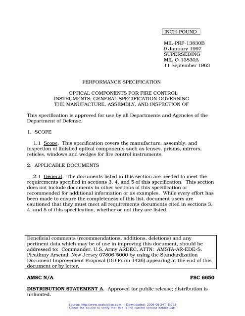
PERFORMANCE SPECIFICATION<br />
OPTICAL COMPONENTS FOR FIRE CONTROL<br />
INSTRUMENTS; GENERAL SPECIFICATION GOVERNING<br />
THE MANUFACTURE, ASSEMBLY, AND INSPECTION OF<br />
This specification is approved for use by all Departments and Agencies of the<br />
Department of Defense.<br />
1. SCOPE<br />
1.1 Scope. This specification covers the manufacture, assembly, and<br />
inspection of finished optical components such as lenses, prisms, mirrors,<br />
reticles, windows and wedges for fire control instruments.<br />
2. APPLICABLE DOCUMENTS<br />
2.1 General. The documents listed in this section are needed to meet the<br />
requirements specified in sections 3, 4, and 5 of this specification. This section<br />
does not include documents in other sections of this specification or<br />
recommended for additional information or as examples. While every effort has<br />
been made to ensure the completeness of this list, document users are<br />
cautioned that they must meet all requirements documents cited in sections 3,<br />
4, and 5 of this specification, whether or not they are listed.<br />
Beneficial comments (recommendations, additions, deletions) and any<br />
pertinent data which may be of use in improving this document, should be<br />
addressed to: Commander, U.S. Army ARDEC, ATTN: AMSTA-AR-EDE-S,<br />
Picatinny Arsenal, New Jersey 07806-5000 by using the Standardization<br />
Document Improvement Proposal (DD Form 1426) appearing at the end of this<br />
document or by letter.<br />
AMSC N/A FSC 6650<br />
DISTRIBUTION STATEMENT A. Approved for public release; distribution is<br />
unlimited.<br />
Source: http://www.assistdocs.com -- Downloaded: 2006-05-24T15:32Z<br />
Check the source to verify that this is the current version before use.
<strong>MIL</strong>-<strong>PRF</strong>-<strong>13830B</strong><br />
2.2 Other Government documents, drawings, and publications. The<br />
following other Government documents, drawings, and publications form a part<br />
of this document to the extent specified herein. Unless otherwise specified, the<br />
issues are those cited in the solicitation.<br />
DRAWINGS<br />
US ARMY ARMAMENT RESEARCH, DEVELOPMENT AND ENGINEERING<br />
CENTER (ARDEC)<br />
C7641866 - Surface Quality Standards for Optical<br />
Elements<br />
(Copies of other Government documents, drawings, and publications required<br />
by contractors in connection with specific acquisition functions should be<br />
obtained from the contracting activity or as directed by the contracting activity.)<br />
2.3 Order of precedence. In the event of a conflict between the text of this<br />
document and the references cited herein, the text of this document takes<br />
precedence. Nothing in this document, however, supersedes applicable laws<br />
and regulations unless a specific exemption has been obtained. (See contract<br />
provisions for additional precedence criteria.)<br />
3. REQUIREMENTS<br />
3.1 General. All optical elements, components and systems shall comply<br />
with the requirements of this specification, except as further defined in the<br />
detailed instrument specification or on applicable drawings forming a part of the<br />
contract.<br />
3.2 Materials. Materials shall be in accordance with applicable<br />
specifications or component or instrument drawings.<br />
3.2.1 Glass, optical. Optical glass shall be of type and grade specified on<br />
the drawings. On authorization to use glass other than that specified, complete<br />
information regarding the optical characteristics of the glass and design data<br />
shall be furnished to the contracting officer.<br />
3.2.1.1 Radioactive material. Optical glass specified herein shall contain no<br />
thorium or other added radioactive materiel in excess of 0.05 percent by weight.<br />
3.2.2 Adhesive. Unless specified by the contract or order, optical cement<br />
shall be in accordance with Appendix A.<br />
2<br />
Source: http://www.assistdocs.com -- Downloaded: 2006-05-24T15:32Z<br />
Check the source to verify that this is the current version before use.
<strong>MIL</strong>-<strong>PRF</strong>-<strong>13830B</strong><br />
3.2.3 Bonding system. Bonding system for glass to metal bonding shall be<br />
in accordance with Appendix D.<br />
3.2.4 Sealing compound. Sealing compound shall be in accordance with<br />
Appendix E.<br />
3.2.5 Reflection reducing film. Reflection reducing film required for coating<br />
of specified optical surfaces shall be in accordance with Appendix C.<br />
3.2.5.1 Reflecting surfaces . Aluminized reflecting surfaces shall be in<br />
accordance with Appendix B.<br />
3.3 Mechanical dimensions. Optical elements shall conform to the<br />
mechanical dimensions and optical data specified on the drawings or in the<br />
contract.<br />
3.3.1 Rim edges. Rim edges of all optical parts shall have a chamfer of<br />
0.020 inch - 0.010 at 45 degrees ± 15 degrees as measured along the face width<br />
unless otherwise specified by the drawing. Edges meeting at angles of 135<br />
degrees and larger need not be beveled unless specified by the drawings.<br />
3.4 Finish and defects. Finish and defects of the optical glass shall conform<br />
with requirements of this specification or as indicated on applicable drawings or<br />
optical diagrams.<br />
3.4.1 Glass defects. Striae, cords, ream, bubbles, seeds, strain, laps, folds<br />
in pressings, or any other defect located in such a point, plane, or position as to<br />
impair the performance of the element shall be cause for rejection of that<br />
element.<br />
3.5 Optical glass surface quality.<br />
3.5.1 Optical drawings and diagrams. Component optical drawings shall<br />
indicate surface quality, and optical system diagrams shall indicate the<br />
diameter of an axial beam of rays.<br />
3.5.1.1 Designation of defect size. Limiting sizes of surface defects shall be<br />
designated on the drawings by two numbers which refer to two graded sets of<br />
surface quality standards per Drawing C7641866. The first number shall refer<br />
to scratches and the second number shall refer to digs (see 6.3).<br />
3.5.2 Scratches.<br />
3.5.2.1 Circular element. The combined length of maximum size scratches<br />
3<br />
Source: http://www.assistdocs.com -- Downloaded: 2006-05-24T15:32Z<br />
Check the source to verify that this is the current version before use.
<strong>MIL</strong>-<strong>PRF</strong>-<strong>13830B</strong><br />
located on each surface of an optical element shall not exceed one quarter the<br />
diameter of that element.<br />
3.5.2.1.1 Maximum combined lengths of scratches. When a maximum size<br />
scratch is present, the sum of the products of the scratch numbers times the<br />
ratio of their length to the diameter of the element or appropriate zone shall not<br />
exceed one half the maximum scratch number. When a maximum size scratch<br />
is not present, the sum of the products of the scratch numbers times the ratio<br />
of their length to the diameter of the element or appropriate zone shall not<br />
exceed the maximum scratch number.<br />
3.5.2.2 Noncircular shaped element. The computing diameter of element<br />
shapes other than circular shall be that of a circle of equal area. Scratches<br />
beyond the free aperature of any element as given on the optical system<br />
drawings or detail drawings shall not be considered when applying the<br />
appropriate formula specified in 3.5.2.1.1.<br />
3.5.2.2.1 True roof surfaces on prisms. True roof surfaces on prisms shall<br />
be considered equivalent to a single surface equal to the sum of the individual<br />
roof areas for purposes of scratch and dig computation, except that the roof<br />
edge shall not be considered in the summation of the length of the allowable<br />
scratches. Scratch and dig tolerances for roof prisms are set on the basis that<br />
the equivalent surface above is viewed from the air side. (3.7.10.1).<br />
3.5.2.2.2 Surface quality, central zone. Areas of surfaces whose specified<br />
scratch qualities are 20 or better shall have no more than 4 separate scratches<br />
in any 1/4-inch diameter circular area. This requirement does not apply for<br />
scratches smaller than number 10.<br />
3.5.2.3 Surface quality, outer zone. Surface quality outside the free<br />
aperture of any element shall be considered 80-50, unless otherwise required.<br />
3.5.2.4 Coating scratches. Coating scratches, scratches which do not<br />
penetrate the glass surface, shall be within the same limits specified in 3.5.2.<br />
Coating scratches shall be considered separate from the substrate scratch<br />
requirements.<br />
3.5.3 Digs.<br />
3.5.3.1 Dig designation. Dig numbers are the actual diameters of defects<br />
allowed, specified in units of 1/100mm. In the case of irregular shaped digs the<br />
diameter shall be taken as the average of the maximum length and maximum<br />
width.<br />
4<br />
Source: http://www.assistdocs.com -- Downloaded: 2006-05-24T15:32Z<br />
Check the source to verify that this is the current version before use.
<strong>MIL</strong>-<strong>PRF</strong>-<strong>13830B</strong><br />
3.5.3.2 Maximum size digs. The permissible number of maximum size digs<br />
shall be one per each 20mm of diameter or fraction thereof on any single optical<br />
surface. The sum of the diameters of all digs as estimated by the inspector<br />
shall not exceed twice the diameter of the maximum size specified per 20mm<br />
diameter. Digs less than 2.5 microns shall be ignored.<br />
3.5.3.3 Surface quality. All digs on each surface whose dig quality is<br />
number 10 or smaller shall be separated edge to edge by at least 1mm. The<br />
measurement of scattering shall not be required for surfaces where digs larger<br />
than number 10 are allowed.<br />
3.5.4 Bubbles and inclusions. Bubbles shall be classed as surface digs.<br />
Any inclusion in the glass shall be treated as a bubble. The size of irregular<br />
shaped inclusions shall be considered as one half the sum of the maximum<br />
length and the maximum width. Bubble size tolerances are identical in all<br />
respects to digs; but the bubble tolerance, is in addition to the dig tolerance.<br />
3.5.4.1 Maximum size bubbles. The permissible number of maximum size<br />
bubbles shall be one per 20mm of light path, or fraction thereof, of any single<br />
element. The sum of the diameters of all bubbles as estimated by the inspector<br />
shall not exceed twice the diameter of the maximum size specified per 20mm<br />
diameter for each 20mm of light path. When surface dig quality is 10 or<br />
smaller, bubbles shall follow requirements for digs as specified in 3.5.3.3.<br />
3.5.5 Limiting size of surface defects. If not specified on drawings, the<br />
limiting size of scratches or digs shall be determined from Table I and is based<br />
on the beam diameter of magnification.<br />
3.5.5.1 Beam diameter of magnification. The beam diameter shall be<br />
obtained from the optical data. It is the diameter at the surface of the optic in<br />
question, of a bundle of axial rays proceeding to the observer's eye. The<br />
diameter of the bundle at the eye shall be taken as 3.5mm, (0.1378 inch) if the<br />
exit pupil is over 3.5mm. If the exit pupil is smaller than 3.5mm, that diameter<br />
of the bundle at the eye shall be the same as the exit pupil.<br />
3.5.5.2 Beam size less than in table I. When the beam size is less than that<br />
specified for focal planes and near local planes of any surface, the size of defect<br />
is determined by the magnification of the eyepiece multiplied by magnification of<br />
the erecting system.<br />
3.5.5.3 Zone. The surface on which the beam diameter of an axial bundle is<br />
25 percent or less of the free aperture shall be divided into a central and outer<br />
zone. The central zone shall be half the free aperture in width. Zone size for<br />
reticles shall be as specified in 3.7.11.1.<br />
5<br />
Source: http://www.assistdocs.com -- Downloaded: 2006-05-24T15:32Z<br />
Check the source to verify that this is the current version before use.
<strong>MIL</strong>-<strong>PRF</strong>-<strong>13830B</strong><br />
3.6 Cement defects. Cement bubbles, voids, undissolved particles, dry<br />
spots, blisters, dirt (lint or dust) within the free aperture of the cemented lens<br />
shall not exceed the limits of defects for digs and bubbles specified in 3.5.3.1<br />
thru 3.5.4.1 inclusive.<br />
Beam diameter (mm)<br />
TABLE I Surface Quality Requirements<br />
Focal planes and near focal planes Central zone 1/2<br />
diameter of surface<br />
Magnifying<br />
power<br />
Focal length<br />
(mm)<br />
Outer Zone<br />
Scratch Dig Scratch Dig<br />
Over 5....................... ......................... .................... 80 50 80 50<br />
4-5............................. ......................... .................... 60 40 60 40<br />
3.2-4.......................... ......................... .................... 60 30 60 40<br />
2.5-3.2 ......................... .................... 40 20 60 40<br />
2.1-2.5....................... ......................... .................... 40 15 60 30<br />
1.6-2.1....................... ......................... .................... 30 10 40 20<br />
1.0-1.6....................... ......................... .................... 20 5 40 15<br />
0.6-1.0....................... ......................... .................... 15 3 30 10<br />
0.4-0.6....................... ......................... .................... 10 2 20 5<br />
0.2-0.4....................... ......................... .................... 10 1 15 3<br />
0.2............................. 20-10 12.5-25 10 1 15 3<br />
0.4............................ 10-5 25-50 10 2 20 5<br />
0. 6 5-3.3 50-75 15 3 30 10<br />
1.0............................ 3.3-2 75-125 20 5 40 15<br />
1.6............................ 2-1 125-250 30 10 40 20<br />
3.6.1 Surface quality of cemented face. Cement defects inside the free aperture<br />
shall be considered on the basis that the cement interface is a single surface of the<br />
specified surface quality. When not specified, the surface quality for a cement face<br />
shall be intermediate between that of adjacent faces.<br />
3.6.2 Edge separations. Edge separation and edge cement defects in optical<br />
components shall not extend beyond the edge chamfer of the cemented surface of the<br />
lens or prism by the distance greater than 1/2 the distance between the cemented<br />
surface chamfer of the component and the radius of the clear aperture. The<br />
maximum dimension of any edge separation or cement defect shall not extend into the<br />
cemented surface of the component by more than 1mm. The sum of the edge<br />
separations or cement defects larger than 1/2mm as measured at the surface chamfer<br />
of the lens or prism, shall not exceed 10 percent of the perimeter.<br />
3.6.3 Bonding defects (glass to metal). Bonded optical assemblies shall have a<br />
continuous bead of the cured adhesive along the edge of the bonded surface.<br />
3.6.3.1 Voids and separations. Subsequent to meeting the requirements of 3.7.2<br />
and 3.8.2.5.2, there shall be no voids or separations that exceed 10 percent of the<br />
bonded area.<br />
6<br />
Source: http://www.assistdocs.com -- Downloaded: 2006-05-24T15:32Z<br />
Check the source to verify that this is the current version before use.
<strong>MIL</strong>-<strong>PRF</strong>-<strong>13830B</strong><br />
3.7 Optical component details.<br />
3.7.1 Temperature operation. Cemented components as a result of exposure to<br />
ambient air temperatures of minus 80 ± 2 degrees and plus 160 ± 2 degrees F shall<br />
not develop "feathering", show evidence of separation or softening of cement or other<br />
defect, except as specified in 3.6, with the provision that the increase or development<br />
of edge separation or edge cement defects shall be cause for rejection.<br />
3.7.2 Relative humidity - temperature operation. Cemented components as a<br />
result of exposure to an ambient atmosphere of plus 130 ± 2 degrees F temperature,<br />
and at least 95 percent minimum relative humidity, and subsequent exposure to<br />
ambient air temperature of minus 80 ± 2 degrees and plus 160 ± 2 degrees F, shall<br />
not develop "feathering", show evidence of separation or softening of cement or other<br />
defects, except as specified in 3.6.<br />
3.7.3 Reflection reducing films. Optical surfaces specified on drawings as<br />
"surfaces to be coated" shall be coated with a reflection reducing film (see 3.2.5).<br />
3.7.4 Optical blackening. When specified, ground surfaces of optical elements<br />
shall be blackened with a finish approved by the responsible technical activity.<br />
3.7.5 Resolution. Resolution tests shall be performed on each objective, collective,<br />
erector, eyepiece, mirror, wedge, window, filter, prism and prism assembly (optical) as<br />
specified in 4.2.5.<br />
3.7.6 Parallelism, filters. Parallelism of filters shall be within the tolerance<br />
specified on the drawings. When no tolerance is specified, filters located internally or<br />
in front of a telescope shall not exceed 1 minute of arc light deviation. Filters located<br />
between the eyelens and the exit pupil shall not have a light deviation exceeding 5<br />
minutes of arc.<br />
3.7.7 Reticle scale spacing. Reticle scale spacing shall be tested in accordance<br />
with 4.2.10.5.<br />
3.7.8 Polished surfaces. Polished surfaces shall show no evidence of grayness or<br />
stain when inspected in accordance with 4.2.2.<br />
3.7.9 Lenses.<br />
3.7.9.1 Surface quality. Surface quality of each lens shall be in accordance with<br />
applicable drawings or instrument specifications. When not specified, the surface<br />
quality shall be as follows: Objectives, erectors, windows and other elements which lie<br />
at least fifteen diopters out of the focal plane, shall have a surface quality of 80-50 or<br />
7<br />
Source: http://www.assistdocs.com -- Downloaded: 2006-05-24T15:32Z<br />
Check the source to verify that this is the current version before use.
<strong>MIL</strong>-<strong>PRF</strong>-<strong>13830B</strong><br />
better. Field and collective lenses shall have a surface quality of 20-5 in the central<br />
zone and 40-15 in the outer zone. Center lenses of oculars shall have a surface<br />
quality of 40-15 in the central zone and 40-20 in the outer zone. Eyelenses, excepting<br />
those in symmetrical eyepieces, shall have a surface quality of 40-20 in the central<br />
zone and 60-30 in the outer zone. When the field and eyelens are identical, the<br />
surface quality for both shall be 20-5 in the central zone and 40-15 in the outer zone.<br />
Filters which lie between the eyelens and the exit pupil shall have a surface quality of<br />
40-20 in the central zone and 60-30 in the outer zone. Filters which lie internally<br />
shall have the same requirements as specified for prisms in 3.7.10.1. Filters located<br />
in front of the objective shall have a surface quality of 80-50 or better.<br />
3.7.9.2 Fractures and edge chips. Edge chips which do not encroach on the free<br />
aperture of the lens shall be allowable, providing the chip does not interfere with the<br />
sealing of the lens in the mount. The surface of all chips larger than 1/2mm, as<br />
measured at the largest extremities, shall be "stoned" to roughen it and lessen the<br />
possibility of annoying reflections and additional chipping. The sum of the chip<br />
widths of chips larger than 1/2mm, as measured at the edge of the lens, shall not<br />
exceed 30 percent of the perimeter. Fractures in any face or edge shall be ground out.<br />
Ground out areas shall remain within the applicable stoned chip limits of this<br />
paragraph. Stoned chips and fractures in ground faces whose total summed up areas<br />
are in excess of 2 percent of the area of the ground face or which are in excess of 2mm<br />
depth shall be cause for rejection. Such stoned chips and fractures shall be cause for<br />
rejection when they interfere with the optical path, mounting or sealing methods<br />
regardless of their size.<br />
3.7.9.3 Concentricity. Edges of all elements shall be trued to diameter about the<br />
optical axis as a center by grinding. Lenses composed of two or more elements shall<br />
be cemented and centered in such a manner that the axis of each element coincides<br />
with the axis or axes of the other element or elements. Ocular lenses shall be<br />
concentric within 6 minutes or arc, and all other lenses shall be concentric within 3<br />
minutes of arc unless otherwise specified on the drawing or in item specifications.<br />
After centering and cementing, mechanical eccentric glass overhang in excess of 50<br />
percent diameter tolerance shall be removed. Optical eccentricity is defined as the<br />
angular deviation, after refraction of an incident ray which is coincident with the<br />
geometric axis of the lens.<br />
3.7.10 Prisms and mirrors.<br />
3.7.10.1 Surface quality. Surface quality of each prism shall be in accordance with<br />
applicable drawings or instrument specifications. For surfaces which lie at least 15<br />
diopters out of the focal plane, quality shall be 80-50 or better. For surfaces which lie<br />
within 5 to 15 diopters of the focal plane the surface quality shall be 20-5 for the<br />
central zone and 40-15 for the outer zone. For surfaces which lie within 5 diopters of<br />
the focal plane surface quality shall be the same as for reticles.<br />
8<br />
Source: http://www.assistdocs.com -- Downloaded: 2006-05-24T15:32Z<br />
Check the source to verify that this is the current version before use.
<strong>MIL</strong>-<strong>PRF</strong>-<strong>13830B</strong><br />
3.7.10.2 Fractures and edge chips. Edge chips which do not encroach on the free<br />
aperture of the prism shall be allowable within the following limitations: The sum of<br />
the chip widths shall not exceed 30 percent of the length of edge on which the chips<br />
occur. Chips shall be measured from the bevelling edge, not from sharp edge; i.e. after<br />
bevelling and not before. Chips less than 1/2mm shall not be counted and not stoned;<br />
chips larger than 1/2mm shall be stoned. Encroachment of chips shall be measured<br />
on the faces of the prism from the bevelled edges. If the nominal length (measured to<br />
sharp corner before bevelling) of the shortest edge of the prism which is adjacent to<br />
any polished face is an inch or less, chips may encroach the faces 1mm; if said length<br />
exceeds 25.4mm chips may encroach 2mm. This shall be permissible provided that<br />
there are no edge chips which interfere with mounting or sealing and the chips do not<br />
encroach upon the free aperture. Fractures visible to the unaided eye on any surface<br />
or edge are not permitted.<br />
3.7.10.3 Drawing requirements. The deviation of angle errors, pyramidal error or<br />
error due to pyramid, spherical power, astigmatism, resolution, and image tilt shall be<br />
as specified on the drawings.<br />
3.7.10.4 Erecting prisms. Erecting prisms shall be inspected as specified in<br />
4.2.5.2.<br />
3.7.10.5 Reflecting surfaces - silvered or aluminized.<br />
3.7.10.5.1 Edges. The edges of partially silvered surfaces of ocular prisms shall be<br />
sharp and shall be free of irregularities when inspected with the aid of a magnifier of at<br />
least the power of the eyepiece of the instrument to which the prism pertains.<br />
3.7.10.5.2 Defects. Defects on reflecting surfaces appear the same as defects on<br />
other optical surfaces and shall be treated in the same manner as specified in 3.7.10.1.<br />
3.7.10.5.3 Aperture surfaces. Aperture surfaces of prisms through which light is<br />
to be transmitted shall be free from particles of silver or aluminum remaining from<br />
processing of other surfaces.<br />
3.7.11 Reticles.<br />
3.7.11.1 Surface quality. The surface quality shall be as specified on the drawings.<br />
When not so specified the surface quality shall be as specified for focal planes in<br />
3.5.5.3, except for zone sizes. The central zone shall be the central area, one half the<br />
free aperture in width, for reticles having reticle graduation extremities within this<br />
area, and those reticles having horizontal and vertical lines without graduations<br />
outside the area. Reticles having graduations outside the central area, one half the<br />
free aperture in width, the central zone shall be the central area, three-fourths the free<br />
9<br />
Source: http://www.assistdocs.com -- Downloaded: 2006-05-24T15:32Z<br />
Check the source to verify that this is the current version before use.
<strong>MIL</strong>-<strong>PRF</strong>-<strong>13830B</strong><br />
aperture in width. Imperfections beyond the free aperture shall be permitted providing<br />
their characteristics do not impair performance of the instrument.<br />
3.7.11.2 Edge chips. Edge chip limitations shall be evaluated in accordance with<br />
3.7.9.2.<br />
3.7.11.3 Parallelism of flat surfaces. Parallelism of reticle flat surfaces shall be<br />
within the tolerances specified by the drawings. Where no tolerance is given on the<br />
drawing, the tolerance shall be 6 minutes of arc deviation of light path.<br />
3.7.11.4 Markings. Reticle markings shall be viewed through an eyepiece of<br />
essentially the same power under which the reticle will be viewed in the finished<br />
instrument. Letters and numerals (whether in part number or adjacent to<br />
graduations) shall be inspected primarily for legibility. Defects in numbers or letters<br />
shall be acceptable provided each letter of figure is legible beyond doubt. Unless<br />
otherwise specified, any printing style is permitted for letters and numbers, however,<br />
the style selected must be uniform throughout each reticle and must meet with the<br />
approval of the procuring agency. Line breaks one half the width of the line shall be<br />
permitted. For reticles containing more than 15 lines, 1 break per 5 lines or fraction<br />
thereof shall be permitted. All lines shall appear to be of uniform width and depth and<br />
the intersections of lines shall appear to be sharp. Smooth or abrupt variations in line<br />
width along the entire line shall not be in excess of 20 percent of the line width and in<br />
no case shall reticle lines be bowed in excess of 1/2 the reticle line width. The fillet<br />
radius at the intersection of reticle lines shall not exceed the line width. Acid burns<br />
shall be cause for rejection, if visible when the reticle is viewed with the appropriate<br />
eyepiece.<br />
3.7.11.5 Illuminated reticles. If the brightness of a defect is greater than the<br />
brightness of a reticle line when illuminated by the associated instrument light or light<br />
of equal intensity, the defect shall be cause for rejection.<br />
3.7.12 Wedge and window. Wedge and window surface quality shall be in<br />
accordance with 3.7.9.1.<br />
3.8 Optical systems.<br />
3.8.1 Unassembled. Optical systems of specified design procured unassembled<br />
shall be grouped into systems in accordance with the optical diagram pertaining to<br />
the system, and shall be inspected as specified in 4.2.9.<br />
3.8.2 Assembled. Optical systems of specified design procured assembled in their<br />
respective instruments shall be assembled in accordance with the drawing and<br />
specification for the instrument, and shall be inspected as specified in 4.2.10.<br />
3.8.2.1 Defect criteria. Defects not otherwise covered in this specification, which<br />
10<br />
Source: http://www.assistdocs.com -- Downloaded: 2006-05-24T15:32Z<br />
Check the source to verify that this is the current version before use.
<strong>MIL</strong>-<strong>PRF</strong>-<strong>13830B</strong><br />
will not impair the performance of the finished instrument, shall be permissible.<br />
Whether a particular defect shall be permitted will depend on the location of the<br />
element in the finished optical system. Defects in elements not near a focal plane are<br />
not as important as in elements which lie in or near a focal plane. In all instances<br />
primary emphasis shall be placed on the performance of the lens or prism rather than<br />
its appearance unless the latter definitely indicates poor workmanship. The order of<br />
importance is as follows:<br />
a. Most critical surfaces,<br />
Etched surface of reticle<br />
Surface of collective lenses in a focal plane<br />
b. Less critical surfaces,<br />
Surface of ocular field lens nearest the reticle,<br />
Collective lens, center lens or prism surfaces near a focal plane<br />
c. Least critical surfaces,<br />
All other surfaces of windows, objectives, prisms,<br />
erector, and eyelenses<br />
3.8.2.2 Alignment. The optical elements of all optical systems procured<br />
assembled in their instruments shall be aligned so that the exit pupil viewed on the<br />
optical axis shall have a minor diameter not less than 90 percent of its major<br />
diameter. The exit pupil shall be concentric with the exit free aperture within 10<br />
percent of the exit free aperture when viewed from a point on the optical axis at a<br />
distance of approximately two feet from the eyelens.<br />
3.8.2.3 Sealed joints. When specified, moisture preventive sealing compound (see<br />
3.2.4) shall be evenly applied to the optical component to form an unbroken bead.<br />
When injection sealing is utilized, 24 hours shall elapse before collimation of the<br />
instrument.<br />
3.8.2.4 Padding. The use of pads, shims, wedges, or opening under or around<br />
optical elements is prohibited and shall be cause for rejection of the instrument unless<br />
specified by the drawings<br />
3.8.2.5 Performance characteristics.<br />
3.8.2.5.1 Vibration. After being subjected to the vibration test specified in 4.2.10.7<br />
the optical instrument shall show no dirt (dust or lint) in excess of that allowed by the<br />
item specification. In the absence of detail requirements, dirt in any confined space<br />
shall not be in size or amounts larger than the allowable dig specification for the<br />
adjacent surface requiring the best dig quality. The instrument shall show no evidence<br />
of loose or damaged parts subsequent to this test.<br />
11<br />
Source: http://www.assistdocs.com -- Downloaded: 2006-05-24T15:32Z<br />
Check the source to verify that this is the current version before use.
<strong>MIL</strong>-<strong>PRF</strong>-<strong>13830B</strong><br />
3.8.2.5.2 Shock. All completed subassemblies in which an optical element is<br />
physically supported from another part or parts by a glass to metal bond shall be<br />
subjected to the shock test.<br />
3.8.2.5.3 Cleanliness. The optical surface of completed instruments shall be clean<br />
and free of condensates and volatile substances when examined by method specified in<br />
4.2.10.9. Dust retention grease shall not be used except with specific authorization of<br />
the responsible technical activity.<br />
3.8.2.5.4 Parallax. Parallax shall be removed where specified in 4.2.10.4.<br />
3.8.2.5.5 Fixed eyepiece focus. Unless otherwise specified the reticle at the center<br />
of the field shall be in sharp focus when the eyepiece is set between minus 0.75 and<br />
minus 1.0 diopter. A calibrated dioptometer with a magnification of at least 3 power or<br />
an equivalent auxiliary telescope shall be used to make this setting.<br />
4. VERIFICATION<br />
4.1 General provisions. Unless otherwise specified in the contract or purchase<br />
order, the supplier is responsible for the performance of all inspection requirements as<br />
specified herein. Except as otherwise specified, the supplier may utilize his own<br />
facilities or any commercial laboratory acceptable to the Government. The Government<br />
reserves the right to perform any of the inspections set forth in the specification where<br />
such inspections are deemed necessary to assure supplies and services conform to<br />
prescribed requirements.<br />
4.1.1 Examination and tests.<br />
a. Classification of characteristics. Conformance examinations and tests are<br />
specified in the item specification’s Classification of Characteristics paragraphs. The<br />
contractor’s quality program or detailed inspection system will provide assurance of<br />
compliance of all characteristics with the applicable drawing and specification<br />
requirements utilizing, as a minimum, the conformance criteria specified. Unless<br />
otherwise cited in the contract or item specification, attributes sampling inspection<br />
shall be conducted in accordance with TABLE II below, using the inspection levels<br />
stated in the Classification of Characteristics paragraphs of the item specification.<br />
12<br />
Source: http://www.assistdocs.com -- Downloaded: 2006-05-24T15:32Z<br />
Check the source to verify that this is the current version before use.
<strong>MIL</strong>-<strong>PRF</strong>-<strong>13830B</strong><br />
For the classification of characteristics, the following definitions apply:<br />
Critical - A critical defect is a defect that judgment and experience indicate would<br />
result in hazardous or unsafe conditions for individuals using, maintaining, or<br />
depending upon the product, or a defect that judgment and experience indicate is<br />
likely to prevent performance of the tactical function of a major end item such as a<br />
tank, land vehicle, missile, aircraft, artillery, or other major weapon system.<br />
Major - A major defect is a defect, other than critical, that is likely to result in failure,<br />
or to reduce materially the usability of the unit of product for its intended purpose.<br />
Minor - A minor defect is a defect that is not likely to reduce materially the usability of<br />
the unit of product for its intended purpose, or is a departure from established<br />
standards having little bearing on the effective use or operation of the unit.<br />
13<br />
Source: http://www.assistdocs.com -- Downloaded: 2006-05-24T15:32Z<br />
Check the source to verify that this is the current version before use.
<strong>MIL</strong>-<strong>PRF</strong>-<strong>13830B</strong><br />
TABLE II. Attributes sample inspection.<br />
Inspection<br />
Levels<br />
I II III IV V VI<br />
Lot Size<br />
2 to 8 * * * * 5 3<br />
9 to 15 * * * 13 5 3<br />
16 to 25 * * * 13 5 3<br />
26 to 50 * * 32 13 5 3<br />
51 to 90 * * 32 13 13 5<br />
91 to 150 * 125 32 13 13 5<br />
151 to 280 * 125 32 32 20 8<br />
281 to 500 * 125 32 32 20 8<br />
501 to 1200 * 125 80 50 20 13<br />
1201 to 3200 1250 125 80 50 32 13<br />
3201 to 1250 125 125 50 32 13<br />
10000<br />
10001 to 1250 315 125 80 50 13<br />
35000<br />
35001 to 1250 315 125 80 50 13<br />
150000<br />
150001 to 1250 500 200 125 50 13<br />
500000<br />
500001 and 1250 500 200 125 50 13<br />
over<br />
Numbers under inspection levels indicate sample size; asterisks (*) indicate one<br />
hundred percent inspection.<br />
If sample size exceeds lot size, perform one hundred percent inspection. Accept<br />
on zero and reject on one or more for all inspection levels.<br />
b. Alternative conformance provisions. Unless otherwise specified herein or<br />
provided for in the contract, alternative conformance procedures, methods or<br />
equipment, such as statistical process control, tool control, variables sampling or<br />
other types of sampling plans, etc., may be used by the contractor when they provide,<br />
as a minimum, the level of assurance required by the provisions herein. Prior to<br />
applying such alternative procedures, methods or equipment, the contractor shall<br />
describe them in a written proposal submitted to the Government for evaluation.<br />
When required, the contractor shall demonstrate that the effectiveness of each<br />
proposed alternative is equal to or better than the specified conformance provision (s)<br />
14<br />
Source: http://www.assistdocs.com -- Downloaded: 2006-05-24T15:32Z<br />
Check the source to verify that this is the current version before use.
<strong>MIL</strong>-<strong>PRF</strong>-<strong>13830B</strong><br />
herein. In case of dispute as to whether the contractor’s proposed alternative (s)<br />
provides equivalent assurance, the provisions of this specification shall apply. All<br />
approved alternative provisions shall be specifically incorporated into the contractor’s<br />
quality program or inspection system, as applicable.<br />
c. Inspection levels. All references to inspection levels in this document and its<br />
appendixes are to utilize the above Table II attributes sample inspection.<br />
4.2 Methods of inspection.<br />
4.2.1 Inspection, optical components. Optical components shall be inspected by<br />
approved optical methods and equipment in accordance with applicable item<br />
specifications. In absence of approved test methods and equipment, the following<br />
procedures of the general specification shall apply. Appropriate sampling procedures<br />
may be used with prior approval of the responsible technical activity.<br />
4.2.1.1 Mechanical dimensions. Each optical component shall be checked for<br />
compliance with the mechanical dimensions of the drawing and shall be inspected in<br />
accordance with the requirements and tests in this specification.<br />
4.2.1.2 Radioactive material. Finished glass shall be tested by X-ray spectrometer<br />
techniques, or an approved alternate, for compliance with 3.2.1.1. Equipment and<br />
method used in performing X-ray fluorescence must have a minimum detectable level<br />
for thorium and other radioactive material of less than 100 parts per million (ppm)<br />
with an accuracy of ± 25 PPM. Should analysis show any sample to exceed the<br />
requirement of 3.2.1.1 all glass in the lot from which the sample was obtained shall be<br />
rejected.<br />
4.2.2 Surface quality. Each element shall be inspected by the following methods<br />
for compliance with 3.5.2, 3.5.5, 3.6.1, 3.7.9.1 and 3.7.10.1.<br />
4.2.2.1 Inspection method No. 1. The element to be inspected shall be viewed<br />
against a ground glass or opal surface illuminated from behind by a 40 watt<br />
incandescent or 15 watt cool white fluorescent lamp approximately 3 inches from the<br />
glass. Two or more opaque horizontal bars occupying approximately 1/2 the area of<br />
the glass shall be placed in front of and in contact with the glass.<br />
4.2.2.2 Inspection method No. 2. The light through ground glass from a 40 watt<br />
incandescent or 15 watt cool white fluorescent lamp shall be passed through the<br />
element. Defects are observed by light scattered from the surface while viewing it at<br />
approximately 90 degrees to the path of the beam against a dark background.<br />
4.2.3 Temperature test.<br />
15<br />
Source: http://www.assistdocs.com -- Downloaded: 2006-05-24T15:32Z<br />
Check the source to verify that this is the current version before use.
<strong>MIL</strong>-<strong>PRF</strong>-<strong>13830B</strong><br />
4.2.3.1 Test No. 1. Three out of the first 10 of each type of cemented or bonded<br />
component completed under each contract shall be tested at the high and low<br />
temperatures specified in 3.7.1. If there is reason to doubt quality, the right is<br />
reserved to test additional samples as the inspector deems necessary. Components<br />
subjected to these tests shall have passed all other required tests.<br />
4.2.3.2 Test No. 2. The cemented or bonded components shall be subjected to an<br />
ambient temperature of minus 80 ± 2 degrees F for 5 hours. When inspected visually<br />
at this temperature, and again after remaining five hours at room temperature, the<br />
optical assembly shall show no evidence of "feathering" or reticulation and there shall<br />
be no separation of the components. In performing this test the optical assemblies<br />
shall not be subjected to any undue thermal shocks while being cooled to minus 80<br />
degrees F, or while being warmed to room temperature.<br />
4.2.3.3 Test No. 3. The cemented optical assembly shall then be subjected to the<br />
following test at the high temperature. One of the components shall be held rigidly in<br />
such a manner that the cemented interface shall be approximately in a vertical plane.<br />
A weight of such magnitude as to induce in the optical assembly a unit shear stress<br />
of 5 ounces per square inch of area of the cemented or bonded surface shall be<br />
suspended from the other component. In no case shall the weight be less than one<br />
ounce. The entire apparatus shall be allowed to soak at an ambient temperature of<br />
plus 160 ± 2 degrees F, for 2 hours. The lens shall pass the requirements specified by<br />
4.2.6 when tested at room temperature and the movement or slippage of one<br />
component with respect to the other shall not exceed .002 inch. In performing this<br />
test the optical assemblies shall not be subjected to any undue thermal shocks while<br />
being raised to 160 degrees F or while being cooled to room temperature.<br />
4.2.3.4 Failure investigation. Failure of one optical assembly shall be cause for<br />
stopping shipments pending an investigation of the cause. The contractor shall<br />
institute an immediate investigation in the presence of a representative of the<br />
contracting officer if the representative desires to be present to determine the cause of<br />
failure. If the investigation discloses a fault in cementing or bonding, acceptance of<br />
optical assemblies incorporating this fault shall be stopped pending correction. The<br />
contractor shall correct his cementing technique and shall correct all faulty optical<br />
assemblies previously produced. Acceptance and shipments will be resumed when<br />
ten consecutive optical assemblies of the type rejected have successfully passed the<br />
temperature tests.<br />
4.2.4 Temperature - relative humidity.<br />
4.2.4.1 Sample size. Three out of the first 10 of each type of cemented or bonded<br />
components at the beginning of each contract, or upon change in method of<br />
cementing or change in type cement, shall be tested at the temperature-humidity<br />
conditions specified herein. If there is reason to doubt quality, the right is reserved to<br />
16<br />
Source: http://www.assistdocs.com -- Downloaded: 2006-05-24T15:32Z<br />
Check the source to verify that this is the current version before use.
<strong>MIL</strong>-<strong>PRF</strong>-<strong>13830B</strong><br />
test additional samples as the inspector deems necessary.<br />
4.2.4.2 Test procedure. The cemented or bonded component shall be gradually<br />
heated in a dry atmosphere to plus 140 ± 2 degrees F, and then immediately placed in<br />
an ambient atmosphere of plus 130 ± 2 degrees F. at 95 percent relative humidity for<br />
2 hours. The optical assemblies shall be removed from the humid atmosphere,<br />
immediately wiped dry, and allowed to cool to room temperature. After 8 hours at<br />
room temperature the component shall be subjected to the tests specified in 4.2.3.2<br />
and 4.2.3.3. The test as specified in this paragraph shall be repeated in the same<br />
identical procedure whenever passable optical assemblies having edge separation or<br />
cement blisters at the start of the test increase, or additional cement defects develop<br />
not in excess of that specified in 3.6. Components failing the initial test, or a change<br />
in any cement defects, or the development of additional cement defects after the retest<br />
shall be cause for rejection including all optical assemblies having passable cement<br />
defects from the corresponding lots offered for inspection. All components subjected<br />
to the humidity tests shall be recemented and recoated if required prior to acceptance.<br />
4.2.4.3 Rejection criteria. Failure of one component to pass the tests specified in<br />
4.2.4 shall be cause for the components to be treated in the same manner as specified<br />
in 4.2.3.4.<br />
4.2.5 Resolution test. Resolution test shall be standard and shall be performed<br />
using one of the resolving power charts, see Figure 1. Resolving power is a measure of<br />
the optical performance. The resolving power is the angular subtense (in seconds of<br />
arc) of a series of parallel bars that can just be resolved. Resolving power is measured<br />
by viewing charts containing parallel bars of appropriate equal spacings. An auxiliary<br />
telescope is used to obtain sufficient magnification. A resolving power chart shall<br />
consist of four sets of lines, all sets either entirely three or entirely four lines at 45<br />
degree steps (horizontal, vertical, and two at 45 degrees). The three line sets shall<br />
contain lines that are five times as long as they are wide. The four line sets shall<br />
contain lines that are seven times as long as they are wide. The widths of lines and<br />
spaces shall be equal. The lines may be either black on a white background, or white<br />
on a black background. There shall be an identifying numeral in the center of the<br />
four sets of lines. The contrast shall be 100:1 minimum. The chart of appropriate<br />
dimensions may be located in a collimator, or it may be viewed directly. In the latter<br />
case, the chart shall be at least 2 M 2 feet from the telescope objective, where M is the<br />
power of the telescope being tested. The angular subtense of a chart is measured in<br />
seconds and equals arc tangent 2W/X, where W is the width of a chart line and X is<br />
either collimator focal length or distance from chart to telescope under test. The<br />
telescope under test is aligned so the chart is in the center of the field. The auxiliary<br />
telescope is added and oriented to again center the chart. With the diopter scale of<br />
the auxiliary telescope at zero, the telescope under test shall be focused on the<br />
numeral in the resolving power target. In reading resolution, the auxiliary telescope<br />
may be focused plus or minus 1/8 diopter for each of the four meridians. All four<br />
17<br />
Source: http://www.assistdocs.com -- Downloaded: 2006-05-24T15:32Z<br />
Check the source to verify that this is the current version before use.
<strong>MIL</strong>-<strong>PRF</strong>-<strong>13830B</strong><br />
meridians shall have the correct line count. The limit of resolution is reached when<br />
individual lines within the pattern are no longer clearly seperated.<br />
4.2.5.1 Objective and erector. When an objective or erector is being inspected by<br />
means of the above chart, it shall be placed at the proper distance and the image<br />
formed by the objective or erector shall be viewed with a microscope at a given power<br />
as required by the item specification or the contracting officer. It shall be possible to<br />
discern a line structure in the blocks equivalent to the resolution specified. The chart<br />
shall be so illuminated as to give a brightness of the image of 10 to 20 millilamberts.<br />
4.2.5.2 Lens. When the effect of the lens on the definition of the complete<br />
instrument is being checked, the other optical component of the instrument having<br />
approved quality shall be arranged exactly as in the actual instrument. The lens to be<br />
tested shall then be inserted in position, and the chart shall be viewed through the<br />
complete setup by means of an auxiliary telescope giving a combined power of 40 to<br />
60 magnifications per inch of aperture. It shall be possible to discern a line structure<br />
in the block representing the line structure required for the specified resolution. The<br />
chart shall be so illuminated as to give a brightness of the image of 10 to 20<br />
millilamberts. Any optical elements needed for this test that are not being<br />
manufactured by the contractor will be furnished by the contracting officer.<br />
4.2.5.3 Image. Plane components used external to a optical system. The<br />
definition shall be tested by observing through the appropriate free aperture of the<br />
component, the image of a target of the form shown in Figure 1. The image shall be<br />
observed with a telescope of at least 5-power greater than the power of the optical<br />
system between the component and the eye.<br />
4.2.5.4 Optical components or partial systems. Optical components or partial<br />
systems procured as such and not as complete systems shall be tested in accordance<br />
with the detail specification or contractual document.<br />
4.2.6 Concentricity of lenses. Cemented and single lenses shall be checked for<br />
conformance with the concentricity requirements of 3.7.9.3. The instrument specified<br />
in 4.2.8 with modifications, may be used for this test except that the reticle in the<br />
collimator shall be capable of being focused to permit placing it in the focal plane of<br />
the lens combination consisting of the collimator objective and the lens undergoing<br />
test for concentricity, and the stage shall be constructed to permit the lens to rotate<br />
about the geometric axis.<br />
4.2.7 Deviation of prisms. The angle of deviation of prisms shall be tested by<br />
checking the deviation of light rays passing through the prisms, by standard or<br />
approved spectrometer practices.<br />
4.2.8 Parallelism. Windows, wedges, reticles or similar flat surfaces elements<br />
18<br />
Source: http://www.assistdocs.com -- Downloaded: 2006-05-24T15:32Z<br />
Check the source to verify that this is the current version before use.
<strong>MIL</strong>-<strong>PRF</strong>-<strong>13830B</strong><br />
shall be tested for parallelism of flat surfaces by checking the deviation of light rays<br />
passing through the element.<br />
4.2.9 Inspection of optical systems procured unassembled.<br />
4.2.9.1 Optical elements. The optical elements of these systems shall be<br />
subjected to the inspection specified in 4.2.1 thru 4.2.8.<br />
4.2.9.2 Systems, grouped. The elements shall be grouped into systems for<br />
inspection and shipments. They shall be spaced, in accordance with the optical<br />
diagram pertaining to the system, and assembled in a master instrument or tester<br />
and tested for definition and quality of image. Elements causing unsatisfactory<br />
performance shall be replaced before acceptance of the system (see Figure 1 for testing<br />
targets, and 4.2.10.2 and 4.2.10.3 for outline of inspection).<br />
4.2.10 Inspection of assembled optical systems.<br />
4.2.10.1 Optical elements. The optical elements of these systems shall be subject<br />
to the inspection specified in 4.2.<br />
4.2.10.2 Target. Targets used in testing optical systems may be either actual size<br />
targets or miniature targets contained in collimators. The actual size targets can be<br />
made by printing black lines on a white background. The target in a collimator may<br />
be an etched or photographic reticle duplicating in miniature form, a full size target.<br />
The targets will vary, as required, by the detailed specification, from plain crosslines<br />
to targets containing a plumb line, level line, tolerance limit lines, and graduated<br />
scales (see Figure 1 for resolution testing target).<br />
4.2.10.2.1 Collimator reticle. The reticle cell of the collimator is adjustable so that<br />
the reticle may be moved toward or away from the objective to represent different<br />
outside distances at which an outside target would be placed. For example, suppose<br />
that the specification for a telescope requires that the instrument be free from parallax<br />
when viewing a target at a distance of 200 yards and a collimator target is to be used<br />
for testing. It is necessary to adjust the collimator reticle to represent this distance.<br />
This may be accomplished by removing parallax in a sample instrument when<br />
observing an outside target at 200 yards and then using this sample telescope to<br />
adjust the collimator reticle until there is no parallax observed when sighting through<br />
the sample telescope at the collimator reticle.<br />
4.2.10.2.2 Image quality. When a collimator target is used to test the image<br />
quality of a telescope, due allowance shall be made for any aberrations of the<br />
collimator objective which will appear to be defects of the telescope being tested.<br />
Caution shall be exercised to eliminate the effect of these aberrations.<br />
19<br />
Source: http://www.assistdocs.com -- Downloaded: 2006-05-24T15:32Z<br />
Check the source to verify that this is the current version before use.
<strong>MIL</strong>-<strong>PRF</strong>-<strong>13830B</strong><br />
4.2.10.3 Instrument, inspection. Where necessary, the field may be observed by<br />
the use of a dioptometer or an equivalent auxiliary telescope to compensate for the<br />
individual inspector's eye accommodation.<br />
4.2.10.4 Parallax. Parallax shall be removed at the center of the field unless<br />
otherwise specified in the detail specification.<br />
4.2.10.5 Reticle scale spacings. Accuracy of angular subtense of reticle scale<br />
spacings of each reticle shall be tested by checking them against a target, which is an<br />
enlarged facsimile of the reticle; or a collimator reticle target. The enlarged target<br />
shall have black lines or marks against a white background and be placed at the<br />
proper distance with the face of the target perpendicular to the line of sight of the<br />
telescopes being tested.<br />
4.2.10.6 Surface quality, reticle. Each reticle shall be checked for compliance<br />
with 3.7.11.1 by viewing with a magnifier whose magnification is equal to or greater<br />
than the pertinent viewing lens of the telescope of which it is a component. The light<br />
and method shall be the same as specified in 4.2.2.<br />
4.2.10.7 Vibration test. Each optical instrument shall be mounted singly or in<br />
groups on an approved vibration machine and fixture and vibrated at an amplitude of<br />
not less than 1/16 inch (1/8 inch total movement at the center of the mounting face<br />
of the fixture) at a frequency of 30 Hz for 2 to 2 1/2 minutes.<br />
4.2.10.8 Shock test. Shock testing of bonded and cement-supported assemblies.<br />
In absence of specific requirements each assembly shall be subjected to shock<br />
acceleration in a direction parallel to the plane of the joint in test for poor adherence<br />
or incomplete curing in the bonded or cemented joint. The time variation of the<br />
acceleration shall be roughly that of a half cycle of a sine function in which the time<br />
for increase of the acceleration from zero to maximum is 0.7 to 2.0 milliseconds. The<br />
amplitude of high frequency components in the time vs. acceleration curve shall not<br />
exceed 30 percent of the fundamental amplitude. Unless otherwise specified by the<br />
item specification, each assembly shall be subjected to six shocks of 150 G peak<br />
acceleration.<br />
4.2.10.9 Cleanliness. Each optical system shall be examined through the<br />
objective and eyepiece ends with the unaided eye. Inspection for moisture shall be<br />
made by the technique of shadowing. Inspection for dust particles shall be made by<br />
viewing a uniformly illuminated field having a brightness of approximately 300<br />
apparent foot-lamberts.<br />
5. PACKAGING<br />
5.1 Packaging. For acquisition purposes, the packaging requirements shall be as<br />
20<br />
Source: http://www.assistdocs.com -- Downloaded: 2006-05-24T15:32Z<br />
Check the source to verify that this is the current version before use.
<strong>MIL</strong>-<strong>PRF</strong>-<strong>13830B</strong><br />
specified in the contract or order. When actual packaging of materiel is to be<br />
performed by DoD personnel, these personnel need to contact the responsible<br />
packaging activity to ascertain requisite packaging requirements. Packaging<br />
requirements are maintained by the Inventory Control Point’s packaging activity<br />
within the Military Department of Defense Agency, or within the Military Department’s<br />
System Command. Packaging data retrieval is available from the managing Military<br />
Department’s or Defense Agency’s automated packaging files, CD-ROM products, or<br />
by contacting the responsible packaging activity.<br />
6. NOTES<br />
(This section contains information of a general or explanatory nature that may be<br />
helpful, but is not mandatory.)<br />
6.1 Intended use. The finished optical components are to be used for fire control<br />
instruments such as sights, telescopes, periscopes and range finders either as<br />
individual elements, partial or complete systems, and assembled or unassembled, as<br />
required by contract.<br />
6.2 Acquisition requirements. Acquisition documents should specify the<br />
following:<br />
a. Title, number and date of this specification.<br />
b. Selection of an applicable level of preservation, packaging and packing.<br />
c. Certified test reports are to be made available to the procuring activity upon<br />
request (see Appendix A and Appendix D).<br />
6.3 Definitions.<br />
6.3.1 Scratch. Any marking or tearing of the surface. Scratch types are identified<br />
as the following:<br />
a. Block reek - chain-like or interrupted scratches that are aligned.<br />
b. Runner-cut or cutter marks - curved scratch caused in grinding.<br />
c. Sleek - hairline scratch.<br />
d. Crush or rub - series of small surface scratches generally caused by<br />
mishandling.<br />
6.3.2 Dig. A small rough spot on the polished surface similar to pits in<br />
21<br />
Source: http://www.assistdocs.com -- Downloaded: 2006-05-24T15:32Z<br />
Check the source to verify that this is the current version before use.
<strong>MIL</strong>-<strong>PRF</strong>-<strong>13830B</strong><br />
appearance, generally residuals of subsurface damage caused by grinding that didn’t<br />
polish out or bubbles that open up.<br />
6.3.3 Feathering. The physical change in cement causing the cement to lose its<br />
adhesion and develop into a feather like pattern.<br />
6.4 Submission of alternative conformance provisions. All contractor proposed<br />
alternative conformance provisions will be submitted to the Government for<br />
evaluation/approval as directed by the contracting activity.<br />
6.5 Drawings. Drawings listed in Section 2 of this specification under the heading<br />
U.S. Army Armament, Research, Development and Engineering Center (ARDEC) may<br />
also include drawings prepared by, and identified as U.S. Army Armament, Research<br />
and Development Command (ARRADCOM), Frankford Arsenal, Rock Island Arsenal or<br />
Picatinny Arsenal drawings. Technical data originally prepared by these activities is<br />
now under cognizance of ARDEC.<br />
6.6 Subject term (key word) listing.<br />
Digs<br />
Reticles<br />
Scratches<br />
Surface Quality<br />
6.7 Changes from previous issue. Marginal notations are not used in this revision<br />
to identify changes with respect to the previous issue due to the extent of the changes.<br />
22<br />
Source: http://www.assistdocs.com -- Downloaded: 2006-05-24T15:32Z<br />
Check the source to verify that this is the current version before use.
<strong>MIL</strong>-<strong>PRF</strong>-<strong>13830B</strong><br />
FIGURE 1. Resolving power chart (for illustration purposes only)<br />
23<br />
Source: http://www.assistdocs.com -- Downloaded: 2006-05-24T15:32Z<br />
Check the source to verify that this is the current version before use.
<strong>MIL</strong>-<strong>PRF</strong>-<strong>13830B</strong><br />
APPENDIX A<br />
ADHESIVE, OPTICAL, THERMOSETTING<br />
A.1 SCOPE<br />
A.1.1 Scope. This appendix covers a thermosetting liquid resin adhesive for<br />
bonding optical elements for use in military optical instruments. This Appendix is a<br />
mandatory part of the specification. The information contained herein is intended for<br />
compliance.<br />
A.2 APPLICABLE DOCUMENTS<br />
A.2.1 General. The documents listed in this section are needed to meet the<br />
requirements specified in sections A.3, A.4, and A.5 of this specification. This section<br />
does not include documents in other sections of this specification or recommended<br />
for additional information or as examples. While every effort has been made to<br />
ensure the completeness of this list, document users are cautioned that they must<br />
meet all requirements documents cited in sections A.3, A.4, and A.5 of this<br />
specification, whether or not they are listed.<br />
A.2.2 Non-Government publications. The following documents form a part of this<br />
document to the extent specified herein. Unless otherwise indicated, the issue in<br />
effect on the date of invitation for bids or request for proposal shall apply.<br />
AMERICAN SOCIETY FOR TESTING AND MATERIALS (ASTM)<br />
ASTM D1084 - Standard Test Methods for Viscosity of Adhesives<br />
(Application for copies should be addressed to American Society for Testing and<br />
Materials, 100 Barr Harbor Drive, West Conshohocken, PA 19428-2959.)<br />
A.2.3 Order of precedence. In the event of a conflict between the text of this<br />
document and the references cited herein, the text of this document takes<br />
precedence. Nothing in this document, however, supersedes applicable laws and<br />
regulations unless a specific exemption has been obtained. (See contract provisions<br />
for additional precedence criteria.)<br />
A.3 REQUIREMENTS<br />
A.3.1 Qualification. The adhesive furnished under this specification shall be a<br />
24<br />
Source: http://www.assistdocs.com -- Downloaded: 2006-05-24T15:32Z<br />
Check the source to verify that this is the current version before use.
<strong>MIL</strong>-<strong>PRF</strong>-<strong>13830B</strong><br />
APPENDIX A<br />
product which has been tested and passed the qualification tests specified herein.<br />
Contractor certified test reports are to be made available upon request. (see A.6.2)<br />
A.3.2 Adhesive. The optical adhesive shall be thermosetting. There shall be no<br />
restriction as to chemical type provided the adhesive meets all requirements specified<br />
herein.<br />
A.3.3 Activator. If necessary, an activator may be used to cure the adhesive and<br />
shall be supplied in the proper quantity for activation with the adhesive.<br />
A.3.4 Refractive index. The refractive index of the polymerized and polymerizable<br />
adhesive shall conform to the following:<br />
A.3.4.1 Polymerized adhesive. The index of refraction of the polymerized adhesive<br />
shall be 1.530 to 1.560 at 25° ± 1°C (77 ± 2°F).<br />
A.3.4.2 Polymerizable adhesive. The index of refraction of the polymerizable<br />
adhesive shall be 1.510 to 1.545 at 25° ± 1°C (77 ± 2°F).<br />
A.3.5 Viscosity. The viscosity of the polymerizable adhesive shall be less than<br />
800 centipoises at 25° ± 1°C (77 ± 2°F).<br />
A.3.6 Light transmission. The light transmission characteristics of the bonded<br />
optical elements shall be greater than or equal to 98.5% within the spectral range of<br />
0.40 to 0.70 micrometers.<br />
A.3.7 Lint and dust particles.<br />
A.3.7.1 Adhesive. Lint and dust particles per 4 ounces polymerizable adhesive<br />
shall not exceed any of the following:<br />
7 particles of 0.1mm maximum length<br />
3 particles of 1.0mm maximum length<br />
1 particles of 5.0mm maximum length<br />
The total number of particles of any size per 4 ounces polymerizable adhesive shall<br />
not exceed 7.<br />
A.3.7.2 Activator. When an activator is used to polymerize the adhesive, the lint<br />
and dust particles in that quantity of activator sufficient to polymerize 4 fluid ounces<br />
of the adhesive shall not exceed any of the following:<br />
25<br />
Source: http://www.assistdocs.com -- Downloaded: 2006-05-24T15:32Z<br />
Check the source to verify that this is the current version before use.
<strong>MIL</strong>-<strong>PRF</strong>-<strong>13830B</strong><br />
APPENDIX A<br />
3 particles of 0.5mm maximum length<br />
1 particles of 1.0mm maximum length<br />
The total number of particles, of any size, shall not exceed 3 in the total quantity of<br />
activator necessary for 4 fluid ounces of adhesive.<br />
A.3.8 Cure conditions. The adhesive shall cure with or without the addition of<br />
activator. When an activator is added, the adhesive shall cure either at room<br />
temperature 25° ± 5°C (77 ± 10°F) in no more than 7 days; or at a temperature not to<br />
exceed 74°C (165°F), in no more than 3 hours. When an activator is not added, the<br />
adhesive may cure by exposure to ultraviolet radiation.<br />
A.3.9 Environmental exposure. Ten bonded doublets (see 4.4) shall be subjected<br />
to three environmental exposure cycles. Each exposure cycle shall include water<br />
immersion, temperature exposure and humidity and shall be conducted in the<br />
following sequence:<br />
a. Immersion in distilled water at 38° ± 2°C (100° ± 4°F) for 22 hours.<br />
b. Exposure at a temperature of -54° ± 2°C (-65° ± 4°F) for 22 hours.<br />
c. Exposure to 95 to 100% relative humidity at 71° ± 1°C (160° ± 2°F) for<br />
22 hours.<br />
Subsequent to the environmental cycles, the bonding layer shall be examined for<br />
evidence of edge separation, feathering, voids, or other forms of bonding layer<br />
disintegration. Each bonded doublet shall be evaluated for its bonding layer defect<br />
and assigned the corresponding weighted value, as defined in Table IA for its<br />
particular defect. The weighted value for the ten doublets shall be arithmetically<br />
averaged and this average weighted value shall be less than five.<br />
A.3.10 Cold exposure. Five bonded doublets shall be exposed to a temperature of<br />
-62° ± 2°C (-80° ± 4°F) for five hours. Subsequent to this cold temperature exposure,<br />
the bonding layer shall be examined for evidence of edge separation, feathering, voids<br />
or other forms of bonding layer disintegration. Each bonded doublet shall be<br />
evaluated for its bonding layer defect and assigned the corresponding weighted value<br />
as defined in Table IA, for its particular defect. The weighted value for the five<br />
doublets shall be arithmetically averaged, and this average weighted value shall be<br />
less than five.<br />
26<br />
Source: http://www.assistdocs.com -- Downloaded: 2006-05-24T15:32Z<br />
Check the source to verify that this is the current version before use.
<strong>MIL</strong>-<strong>PRF</strong>-<strong>13830B</strong><br />
APPENDIX A<br />
A.3.11 Instruction sheet. The manufacturer shall provide an instruction sheet or<br />
pamphlet when requesting qualification and also with each unit package of adhesive<br />
outlining instructions for its use. The instruction sheet shall include as a minimum<br />
the following information:<br />
a. Manufacturer’s designation for the adhesive and a description of the base<br />
polymer(s) and modifiers, if any, used in the adhesive.<br />
b. Mixing instructions, including type and amount of activators, if required, and<br />
temperature controls during mixing and minimum pot life of the mixed<br />
adhesive.<br />
c. Complete processes and treatments for preparing the glass surfaces prior to<br />
their bonding with the adhesive.<br />
d. Application instructions including the method of applying the adhesive to a<br />
glass surface and joining two glass surfaces together.<br />
e. Curing times and temperature, including any pre-cure or post-cure<br />
procedures.<br />
f. Suggested methods for decementing any poorly bonded assemblies.<br />
g. Necessary safety precautions to be observed throughout all operations.<br />
h. Any other pertinent information relative to the use and storage of the<br />
adhesive or activator, or both.<br />
A.4. VERIFICATION<br />
A.4.1 General provisions. Unless otherwise specified in the contract or purchase<br />
order, the supplier is responsible for the performance of all inspection requirements<br />
as specified herein. Except as otherwise specified, the supplier may utilize his own<br />
facilities or any facilities suitable for the performance of the inspection requirements<br />
specified herein, unless disapproved by the government. The government reserves<br />
the right to perform any of the inspections set forth in the specification where such<br />
inspections are deemed necessary to assure that supplies and services conform to<br />
prescribed requirements.<br />
27<br />
Source: http://www.assistdocs.com -- Downloaded: 2006-05-24T15:32Z<br />
Check the source to verify that this is the current version before use.
<strong>MIL</strong>-<strong>PRF</strong>-<strong>13830B</strong><br />
APPENDIX A<br />
TABLE IA. Weighted Value<br />
WEIGHTED<br />
VALUE BONDED LAYER DEFECT DESCRIPTION DEFECT TOLERANCE<br />
0 Perfect No defects in bonded surface<br />
1 A separation from bevel into bonded surface<br />
at the periphery for 0 - 49% of the<br />
circumference<br />
2 A separation from bevel into bonded surface<br />
at the periphery for 50 - 100% of the<br />
circumference<br />
Up to 1.0mm penetration<br />
Up to 1.0mm penetration<br />
3 Same as #1 Up to 2.0mm penetration<br />
4 Same as #2 Up to 2.0mm penetration<br />
5 Same as #1 Up to 3.0mm penetration or bubble,<br />
void, or separation in the bonded<br />
surface greater than 0.41mm<br />
diameter but less than 1.0mm<br />
6 A separation from bevel into bonded surface<br />
at the periphery for 50-100% of the<br />
circumference or a void, bubble, or<br />
separation in bonded surface.<br />
Up to 3.0mm penetration or a bubble,<br />
void, or separation in the bonded<br />
surface greater than 0.41mm<br />
diameter but less than 1.0mm.<br />
7 A separation from bevel into bonded surface<br />
at the periphery for 0 - 49% of the<br />
circumference of void, bubble or separation<br />
in bonded surface.<br />
Up to 4.0mm penetration or a bubble,<br />
void, or separation greater than<br />
1.1mm in diameter in bonded surface.<br />
8 Same as #6 Same as #7<br />
9 Any film condition worse than #8 with<br />
description noted.<br />
Same as #7<br />
A.4.2 Classification of tests. The inspection and testing of the adhesive shall be<br />
classified as follows:<br />
a. Qualification test (4.5)<br />
b. Conformance tests (4.6)<br />
28<br />
Source: http://www.assistdocs.com -- Downloaded: 2006-05-24T15:32Z<br />
Check the source to verify that this is the current version before use.
<strong>MIL</strong>-<strong>PRF</strong>-<strong>13830B</strong><br />
APPENDIX A<br />
A.4.3 Preparation of glass discs. Glass discs as specified in Figure 1A shall be<br />
prepared in sufficient quantities to furnish the necessary number of bonded doublets<br />
required for the applicable tests of this specification. The optical characteristics of<br />
these discs shall be equal.<br />
A.4.4 Preparation of bonded doublets. Glass discs, as specified in A.4.3, shall be<br />
thoroughly cleaned with ethyl alcohol and a camel hair brush prior to bonding. The<br />
adhesive shall be applied dropwise to the center of one of the cleaned discs and<br />
another disc placed on the adhesive-laden surface. Pressure shall be applied to<br />
spread the adhesive film evenly between the adherends employing rotary movement<br />
of the top element to obtain a bubble free film. Excessive adhesive shall be wiped<br />
from the periphery of the doublet and the film shall be cured in accordance with the<br />
manufacturer’s instructions and in compliance with A.3.8.<br />
A.4.5 Qualification tests.<br />
A.4.5.1 Qualification tests. Qualification tests shall consist of all tests of this<br />
specification. (See A.6.3)<br />
A.4.5.1.1 Sample size. The sample size of material for qualification testing shall<br />
be as directed by the qualifying activity.<br />
A.4.5.1.2 Manufacturer's data. Two copies of the manufacturer's test report,<br />
containing complete test data certifying that the material submitted for qualification<br />
conforms to this specification shall be submitted with qualification test samples.<br />
Location and identity of the plant which produced the samples tested shall also be<br />
stated.<br />
A.4.5.1.3 Instruction sheet. Duplicate copies of the manufacturer's instructions<br />
for use of the adhesive shall be furnished with the qualification samples. (See A.3.11)<br />
A.4.5.1.4 Refractive index.<br />
A.4.5.1.4.1 Polymerized adhesive. The index of refraction of the polymerized<br />
adhesive shall be measured using an Abbe refractometer at 25° ± 1°C (77° ± 2°F)<br />
using a white-light source to determine conformance with A.3.4.1.<br />
A.4.5.1.4.2 Polymerizable adhesive. The index of refraction of polymerizable<br />
adhesive shall be measured with an Abbe refractometer at 25° ± 2°C (77° ± 2°F) using<br />
a white-light source to determine conformance with A.3.4.2.<br />
29<br />
Source: http://www.assistdocs.com -- Downloaded: 2006-05-24T15:32Z<br />
Check the source to verify that this is the current version before use.
<strong>MIL</strong>-<strong>PRF</strong>-<strong>13830B</strong><br />
APPENDIX A<br />
A.4.5.1.5 Viscosity. The viscosity of the polymerizable adhesive shall be<br />
measured with a Brookfield Visometer, corrected to 25° ± 1°C (77° ± 2°F), in<br />
accordance with Method B, ASTM 1084.<br />
A.4.5.1.6 Light transmission. The light transmission characteristics of the<br />
adhesive shall be determined using a dual-beam spectrophotometer. The test shall<br />
be performed by applying a layer of standard mineral oil (refractive index 1.47)<br />
between two glass discs to form a doublet. Prepare a total of two doublets in this<br />
manner. One of these doublets is then placed in both the reference and sample beam<br />
of the spectrophotometer. The spectrophotometer is than calibrated to obtain a<br />
100% level throughout the visible spectrum from 0.40 to 0.70 micrometers. Doublets<br />
bonded with the adhesive under examination are then individually placed in the<br />
sample compartment (the standard mineral oil sample is replaced by the adhesive<br />
bonded doublet) and measured for compliance with A.3.6.<br />
A.4.5.1.7 Dust and lint content. The cleanliness of the polymerizable adhesive<br />
and activator, if required, shall be inspected by placing the sample between two<br />
polarizing filters whose faces are placed parallel and whose axes of polarization are<br />
crossed at 90°. A diffuse white light source is placed in front of the first filter and<br />
viewed from behind the second filter to determine conformance with A.3.7.<br />
A.4.5.1.8 Environmental exposure. Ten bonded doublets, prepared in accordance<br />
with A.4.4, shall be subjected to three environmental exposure cycles (of 3 tests each<br />
cycle) as specified in A.3.9. After each test within the cycle, the bonded doublets<br />
shall be allowed to cool or warm to room temperature before proceeding to the next<br />
test. Subsequent to exposure to the three environmental cycles, the bonded doublets<br />
shall be examined with the aid of one to three power (1X to 3X) magnification to<br />
determine conformance to A.3.9.<br />
NOTE: Caution shall be exercised throughout this environmental exposure<br />
subjecting the doublets to thermal shock.<br />
A.4.5.1.9 Cold exposure. Five bonded doublets, prepared in accordance with<br />
A.4.4, shall be subjected to the cold exposure specified in A.3.10. After exposure, the<br />
doublets shall be allowed to warm to ambient room temperature. The bonded<br />
doublets shall then be examined with the aid of one to three power (1X to 3X)<br />
magnification to determine conformance to A.3.10.<br />
NOTE: Caution shall be exercised throughout this cold exposure to avoid subjecting<br />
the bonded doublets to thermal shock.<br />
30<br />
Source: http://www.assistdocs.com -- Downloaded: 2006-05-24T15:32Z<br />
Check the source to verify that this is the current version before use.
<strong>MIL</strong>-<strong>PRF</strong>-<strong>13830B</strong><br />
APPENDIX A<br />
A.4.5.2 Qualification retest. Unless otherwise specified by the procuring activity,<br />
adhesives which have previously passed the qualification tests but have subsequently<br />
been modified in any manner, shall satisfactorily pass retesting of the material in<br />
order to retain qualification approval. Qualification tests may be repeated on<br />
material previously found satisfactory at any time at the option of the activity<br />
responsible for qualification approval. Failure will constitute cause for removal from<br />
Qualified Products List.<br />
A.4.6 Conformance test. Quality conformance test shall consist of the sampling<br />
plans specified in A.4.6.1.<br />
A.4.6.1 Sampling for inspection and acceptance. Two unit bottles of adhesive<br />
and two bottles of activator (sufficient to cure the adhesive) if required, shall be<br />
selected at random from each lot. The adhesive in each container shall be subjected<br />
to the following determinations. If either sample fails any test, the lot shall be<br />
rejected.<br />
5. PACKAGING<br />
a. Refractive index of polymerizable adhesive (A.4.5.1.4.2).<br />
b. Viscosity (A.4.5.1.5).<br />
5.1 Packaging. For acquisition purposes, the packaging requirements shall be as<br />
specified in the contract or order (see A6.2). When actual packaging of materiel is to<br />
be performed by DoD personnel, these personnel need to contact the responsible<br />
packaging activity to ascertain requisite packaging requirements. Packaging<br />
requirements are maintained by the Inventory Control Point’s packaging activity<br />
within the Military Department of Defense Agency, or within the Military<br />
Department’s System Command. Packaging data retrieval is available from the<br />
managing Military Department’s or Defense Agency’s automated packaging files, CD-<br />
ROM products, or by contacting the responsible packaging activity.<br />
A.6. NOTES<br />
(This section contains information of a general or explanatory nature that may be<br />
helpful, but is not mandatory.)<br />
A.6.1 Intended use. The adhesive covered by this specification is intended for<br />
bonding optical elements in military optical systems.<br />
31<br />
Source: http://www.assistdocs.com -- Downloaded: 2006-05-24T15:32Z<br />
Check the source to verify that this is the current version before use.
<strong>MIL</strong>-<strong>PRF</strong>-<strong>13830B</strong><br />
APPENDIX A<br />
A.6.2 Acquisition requirements. Acquisition documents should specify the<br />
following:<br />
a. Title, number and date of this specification<br />
b. Quantity desired<br />
c. Size of container: 1oz or 4oz<br />
d. Certified test report for this adhesive shall be available upon request by the<br />
procuring activity.<br />
e. Special Markings:<br />
1. Adhesive Optical Thermosetting<br />
2. Specification<br />
3. Manufacturer’s name and address<br />
4. Volume contained<br />
5. Lot number<br />
6. Manufacturer’s designation<br />
7. Date of manufacture<br />
8. Store in cool, dark place<br />
32<br />
Source: http://www.assistdocs.com -- Downloaded: 2006-05-24T15:32Z<br />
Check the source to verify that this is the current version before use.
<strong>MIL</strong>-<strong>PRF</strong>-<strong>13830B</strong><br />
APPENDIX A<br />
NOTE: Glass type BK7 or equivalent<br />
Surfaces marked “P” polish, surface quality 80-50<br />
FIGURE 1A. Glass disc (dimensions in inches)<br />
33<br />
Source: http://www.assistdocs.com -- Downloaded: 2006-05-24T15:32Z<br />
Check the source to verify that this is the current version before use.
<strong>MIL</strong>-<strong>PRF</strong>-<strong>13830B</strong><br />
APPENDIX B<br />
MIRROR, FRONT SURFACED ALUMINIZED,<br />
FOR OPTICAL ELEMENTS<br />
B.1 SCOPE<br />
B.1.1 Scope. This specification covers a mirror coating consisting of a deposited<br />
aluminum reflective film overlaid with a transparent dielectric protective film applied<br />
on the front surface of optical elements. This Appendix is a mandatory part of the<br />
specification. The information contained herein is intended for compliance.<br />
B.2 APPLICABLE DOCUMENTS<br />
B.2.1 General. The documents listed in this section are needed to meet the<br />
requirements specified in sections 3, 4, and 5 of this specification. This section does<br />
not include documents in other sections of this specification or recommended for<br />
additional information or as examples. While every effort has been made to ensure<br />
the completeness of this list, document users are cautioned that they must meet all<br />
requirements documents cited in sections 3, 4, and 5 of this specification, whether or<br />
not they are listed.<br />
B.2.2 Non-Government publications. The following documents form a part of this<br />
document to the extent specified herein. Unless otherwise indicated, the issue in<br />
effect on the date of invitation for bids or request for proposal shall apply.<br />
AMERICAN SOCIETY FOR TESTING AND MATERIALS (ASTM)<br />
ASTM B117 - Standard Practice for Operating Salt Spray (Fog) Testing Apparatus<br />
(Application for copies should be addressed to American Society for Testing and<br />
Materials, 100 Barr Harbor Drive, West Conshohocken, PA 19428-2959.)<br />
B.2.3 Order of precedence. In the event of a conflict between the text of this<br />
document and the references cited herein, the text of this document takes<br />
precedence. Nothing in this document, however, supersedes applicable laws and<br />
regulations unless a specific exemption has been obtained. (See contract provisions<br />
for additional precedence criteria.)<br />
B.3 REQUIREMENTS<br />
34<br />
Source: http://www.assistdocs.com -- Downloaded: 2006-05-24T15:32Z<br />
Check the source to verify that this is the current version before use.
<strong>MIL</strong>-<strong>PRF</strong>-<strong>13830B</strong><br />
APPENDIX B<br />
B.3.2 Optical elements. The supplier is responsible for the quality of the optical<br />
elements used as backing for a front surface mirrored finish. Optical elements shall<br />
have been manufactured, tested and approved for use in accordance with the<br />
applicable element drawing and referenced specifications prior to the coating process.<br />
B.3.3 Coating process. The coating process producing the front surface mirror<br />
finish shall cause no impairment to the optical element. Optical elements which have<br />
met the requirements of B.3.2 shall not be rejected because of fine hair lines,<br />
scratches, digs or stains which are made more visible by the coating process.<br />
B.3.3.1 Aluminum film. The deposited film shall be of high quality aluminum.<br />
There shall be no visible discontinuities or blemishes that adversely affect the field of<br />
view as seen with the eye in the specified viewing position.<br />
B.3.3.2 Protective film. The front surface aluminum film shall be protected by a<br />
film of high quality uniform magnesium fluoride or silicon monoxide or as otherwise<br />
specified on the applicable drawing. The film shall be free from holes, foreign matter<br />
and perceptible variations in density.<br />
B.3.4 Reflectance. The finished coated surface, for visible use, shall have more<br />
than 80 percent luminous reflectance when measured at required angle of incidence,<br />
or a reflectance as otherwise specified on the applicable drawing.<br />
B.3.5 Optical quality. The finished coated surface shall conform to the pertinent<br />
optical requirements set forth on the applicable drawing.<br />
B.3.6 Coated area. The optical element shall be coated over its entire effective<br />
aperture or as otherwise specified by the applicable drawing.<br />
B.3.7 Temperature influence. The coated surface shall show no signs of<br />
deterioration or removal of films after being subjected to ambient temperature of -80°<br />
± 2° F and also +160° ± 2° F for a period of five hours at each temperature.<br />
B.3.8 Hardness. The coated surface shall show no signs of deterioration such as<br />
streaks or hairline scratches as defined in <strong>MIL</strong>-<strong>PRF</strong>-13830 after being hand rubbed<br />
with a dry cloth.<br />
B.3.9 Adherence. No part of the aluminum or protective films shall be removed<br />
when cellophane tape is pressed against the coated surface and slowly removed.<br />
B.3.10 Humidity and salt spray. When specified in the contract the coated<br />
35<br />
Source: http://www.assistdocs.com -- Downloaded: 2006-05-24T15:32Z<br />
Check the source to verify that this is the current version before use.
<strong>MIL</strong>-<strong>PRF</strong>-<strong>13830B</strong><br />
APPENDIX B<br />
surface shall show no evidence of corrosion or pitting when exposed to a relative<br />
humidity of 95 to 100 percent at 120°F ± 4°F for a period of 24 hours and when<br />
exposed to a salt spray for the same time period. (See B.6.1)<br />
B.4. VERIFICATION<br />
TABLE IB, Classification of Defects<br />
INSPECTION LEVEL III<br />
Class Requirement Test Procedure<br />
Critical: None defined<br />
Major:<br />
101. Aluminum film B.3.3.1 B.4.4.1<br />
102. Protective film B.3.3.2 B.4.4.1<br />
103. Reflectance B.3.4 B.4.4.2<br />
104. Optical quality B.3.5 B.4.4.3<br />
105. Coated area B.3.6 B.4.4.1<br />
106. Temperature influence B.3.7 B.4.4.4<br />
107. Hardness B.3.8 B.4.4.5<br />
108. Adherence B.3.9 B.4.4.6<br />
109. Humidity B.3.10 B.4.4.7<br />
110. Salt spray B.3.10 B.4.4.8<br />
Minor: None defined<br />
B.4.4 Methods of inspection.<br />
B.4.4.1 Coating process. Use a visual inspection and procedures set forth in<br />
<strong>MIL</strong>-<strong>PRF</strong>-13830 para. 4.2.2 to determine compliance with requirements B.3.3.1,<br />
B.3.3.2, and B.3.6.<br />
B.4.4.2 Reflectance. The reflectance of the finished mirror at the required angle<br />
of incidence shall be measured either with a photometer for luminous reflectance or<br />
an instrument (spectrophotometer) capable of measuring nonvisual reflectance as<br />
otherwise specified on the applicable drawing to determine conformance with the<br />
requirements of B.3.4.<br />
B.4.4.3 Optical quality. Use testing procedures as specified in para. 4.4.2 of <strong>MIL</strong>-<br />
36<br />
Source: http://www.assistdocs.com -- Downloaded: 2006-05-24T15:32Z<br />
Check the source to verify that this is the current version before use.
<strong>MIL</strong>-<strong>PRF</strong>-<strong>13830B</strong><br />
APPENDIX B<br />
<strong>PRF</strong>-13830 or as otherwise specified on applicable drawing to determine compliance<br />
with requirement B.3.5.<br />
B.4.4.4 Temperature influence. The element shall be exposed to ambient<br />
temperatures of -80° ± 2°F and +160° ± 2°F for a period of 5 hours at each specified<br />
temperature. A visual inspection shall be made after the element is returned to<br />
standard ambient temperature (+60° to 90°F) to determine compliance with the<br />
requirement B.3.7.<br />
B.4.4.5 Hardness. This test shall be performed using a pad of clean, dry,<br />
cheesecloth, approximately 3/8 inch diameter and 1/2 inch thick. Bearing with a<br />
force of one pound ± 1/4 lb. on the protected clean surface of the element, rub a<br />
minimum of 50 strokes across the surface in straight lines or circular motions.<br />
Subsequent to this procedure the protective coating must meet the requirements of<br />
B.3.8.<br />
B.4.4.6 Adherence. Place the sticky surface of cellophane tape over a portion of<br />
the coated surface. Press the tape firmly against the coated surface. Pull the tape<br />
down over the edges of the element and then slowly remove the tape. A visual<br />
inspection shall be made of the tested area to assure that the films have not been<br />
removed from the substrate material to determine compliance with B.3.9. Edges not<br />
forming a part of the reflecting surface shall not be considered when inspection is<br />
being performed.<br />
B.4.4.7 Humidity. The coated elements shall be exposed for a period of 24 hours<br />
in a thermostatically controlled humidity chamber having a relative humidity of<br />
between 95 and 100 percent at 120° ± 4°F. The elements shall be removed from the<br />
chamber and dried with lens tissue or soft cloth, then visually inspected to determine<br />
compliance with the requirements of B.3.10. (see B.6.1)<br />
B.4.4.8 Salt spray. A visual inspection of the element shall be made of the<br />
coating after exposure to the salt spray test in accordance with ASTM B117.<br />
B.5 PACKAGING<br />
(This section is not applicable to this appendix.)<br />
B.6 NOTES<br />
(This section contains information of a general or explanatory nature that may be<br />
helpful, but is not mandatory.)<br />
37<br />
Source: http://www.assistdocs.com -- Downloaded: 2006-05-24T15:32Z<br />
Check the source to verify that this is the current version before use.
<strong>MIL</strong>-<strong>PRF</strong>-<strong>13830B</strong><br />
APPENDIX B<br />
B.6.1 Humidity and salt spray. Humidity and salt spray requirements and tests<br />
are applicable only when specifically required by contract. The contract shall also<br />
prescribe the specific protective coating that will meet the environmental<br />
requirements of B.3.10.<br />
38<br />
Source: http://www.assistdocs.com -- Downloaded: 2006-05-24T15:32Z<br />
Check the source to verify that this is the current version before use.
<strong>MIL</strong>-<strong>PRF</strong>-<strong>13830B</strong><br />
APPENDIX C<br />
COATING OF GLASS OPTICAL ELEMENTS<br />
(ANTI-REFLECTION)<br />
C.1. SCOPE<br />
C.1.1 Scope. This appendix establishes the minimum optical and durability<br />
requirements for magnesium fluoride interference films used as anti-reflection<br />
coatings on optical materials. This Appendix is a mandatory part of the specification.<br />
The information contained herein is intended for compliance.<br />
C.2. APPLICABLE DOCUMENTS<br />
C.2.1 General. The documents listed in this section are needed to meet the<br />
requirements specified in sections 3, 4, and 5 of this specification. This section does<br />
not include documents in other sections of this specification or recommended for<br />
additional information or as examples. While every effort has been made to ensure<br />
the completeness of this list, document users are cautioned that they must meet all<br />
requirements documents cited in sections 3, 4, and 5 of this specification, whether or<br />
not they are listed.<br />
C.2.2 Other Government documents, drawings, and publications. The following<br />
other Government documents, drawings, and publications form a part of this<br />
document to the extent specified herein. Unless otherwise specified, the issues are<br />
those cited in the solicitation.<br />
DRAWINGS<br />
U.S. Army Armament Research, Development and Engineering Center (ARDEC)<br />
C7641866<br />
D7680606<br />
Surface Quality Comparison Standards<br />
Coating, Eraser Abrasion Tester<br />
(Copies of other Government documents, drawings, and publications required by<br />
contractors in connection with specific acquisition functions should be obtained from<br />
the contracting activity or as directed by the contracting activity.)<br />
C.2.3 Non-Government publications. The following document(s) form a part of<br />
this document to the extent specified herein. Unless otherwise specified, the issues<br />
of the documents which are DoD adopted are those listed in the issue of the DODISS<br />
39<br />
Source: http://www.assistdocs.com -- Downloaded: 2006-05-24T15:32Z<br />
Check the source to verify that this is the current version before use.
<strong>MIL</strong>-<strong>PRF</strong>-<strong>13830B</strong><br />
APPENDIX C<br />
cited in the solicitation. Unless otherwise specified, the issues of documents not<br />
listed in the DODISS are the issues of the documents cited in the solicitation (see<br />
C6.2).<br />
AMERICAN SOCIETY FOR TESTING AND MATERIALS (ASTM)<br />
ASTM B117 - Standard Practice for Operating Salt Spray (Fog) Testing Apparatus<br />
(Applications for copies should be addressed to the American Society for Testing and<br />
Materials, 100 Barr Harbor Drive, West Conshohocken, PA 19428-2959.)<br />
C.2.4 Order of precedence. In the event of a conflict between the text of this<br />
document and the references cited herein, the text of this document takes<br />
precedence. Nothing in this document, however, supersedes applicable laws and<br />
regulations unless a specific exemption has been obtained. (See contract provisions<br />
for additional precedence criteria.)<br />
C.3. REQUIREMENTS<br />
C.3.2 Materials. The material used for coating shall be a pure grade of<br />
Magnesium Fluoride adequate to meet all requirements of this specification.<br />
C.3.3 Coated area. Optical components shall be coated over their entire clear<br />
aperture. In those instances where the clear aperture is not specified on the<br />
component drawing or procurement document the following allowable uncoated<br />
holding area shall apply:<br />
Diameter or Maximum<br />
Diagonal Dimension<br />
of Optical Element<br />
Maximum Width of<br />
Uncoated Area<br />
Up to 2” 0.040”<br />
Greater than 2”<br />
0.040”plus additional width of<br />
0.015” for each inch in<br />
diagonal greater than 2”<br />
OR<br />
Up to 5 CM<br />
Greater than 5 CM<br />
OR<br />
1 MM<br />
1 MM plus additional width<br />
increasing at the rate of 0.15<br />
MM for each CM over 5 CM<br />
40<br />
Source: http://www.assistdocs.com -- Downloaded: 2006-05-24T15:32Z<br />
Check the source to verify that this is the current version before use.
<strong>MIL</strong>-<strong>PRF</strong>-<strong>13830B</strong><br />
APPENDIX C<br />
In those instances where the clear aperture is specified, areas outside the clear<br />
aperture may be coated at the discretion of the contractor.<br />
C.3.4 Coating quality. The coating shall be uniform in quality and condition and<br />
shall conform to the following:<br />
C.3.4.1 Physical. The coating shall show no evidence of deterioration such as<br />
flaking, peeling, cracking or blistering.<br />
C.3.4.2 Cosmetic. No stains, smears, streaks, or cloudiness shall be permitted<br />
on optical components lying in a focal plane beyond those permitted by the<br />
component drawing. Unless otherwise specified on the component drawing or<br />
procurement document, visual discolorations such as stains, smears, streaks,<br />
cloudiness, etc. on optical components which lie outside a focal plane in an optical<br />
system shall be acceptable when the stained area of the coated component conforms<br />
to the following as applicable:<br />
a. The transmission requirements of C.3.5.<br />
b. The reflection requirements of C.3.7.<br />
c. The adhesion requirement of C.3.8.5.<br />
d. The severe abrasion resistance requirement of C.3.8.4.1 for substrates<br />
having a Knoop hardness greater than 450 kg/mmì ; or the abrasion<br />
resistance requirement of C.3.8.4.2 for substrates having a Knoop<br />
hardness less than 450 kg/mmì .<br />
NOTE: For purposes of this specification, should a question arise as to whether an<br />
optical component lies at or outside the focal plane, it will be assumed that it lies at<br />
the focal plane.<br />
C.3.4.3 Spatter and holes. Coating spatter and holes shall be considered as a dig<br />
and shall not exceed the allowable dig size and quality stated on the component<br />
drawing or procurement document.<br />
C.3.4.4 Surface defects (scratch and dig). Coating scratches and digs shall not<br />
exceed the values specified for the substrate on the component drawing or<br />
procurement document. Coating scratches and digs shall be considered separate<br />
from the substrate scratch and dig requirements.<br />
41<br />
Source: http://www.assistdocs.com -- Downloaded: 2006-05-24T15:32Z<br />
Check the source to verify that this is the current version before use.
<strong>MIL</strong>-<strong>PRF</strong>-<strong>13830B</strong><br />
APPENDIX C<br />
C.3.5 Transmission. The increase in transmission of an element after coating at<br />
the wavelength that corresponds to a coating with a quarter wave optical thickness<br />
(QWOT) (See C.6.3) shall be equal to or greater than the value specified in Figure 1C,<br />
as applicable to the substrate’s refractive index and surface(s) coated.<br />
C.3.6 Film thickness. Unless otherwise specified on the component drawing or<br />
procurement document, the coating shall have a QWOT between 0.45 um and 0.60<br />
um (See C.6.2)<br />
C.3.7 Reflectance (at the minimum point). The magnitude of the specular<br />
reflectance for each coated surface at the minimum point on the spectral reflectance<br />
curve shall not exceed the values shown in Figure 2C, according to the refractive<br />
index of the substrate.<br />
C.3.8 Durability.<br />
C.3.8.1 Salt solubility. After immersion in a saline solution for a period of 24<br />
hours, the coated surface shall meet the requirement of C.3.4.1 and the applicable<br />
abrasion resistance requirement of C.3.8.4.<br />
C.3.8.2 Humidity. After exposure to an atmosphere of 120° “ 4°F (48.9° “ 2.2°C)<br />
and 95 to 100% relative humidity, the coated surface shall meet the requirements of<br />
C.3.4.1 and the applicable abrasion reistance requirement of C.3.8.4.<br />
C.3.8.3 Salt spray fog. After exposure to a salt spray fog for a continuous period<br />
of 24 hours, the coated surface shall meet the requirements of C.3.4.1 and the<br />
applicable abrasion resistance requirements of C.3.8.4.<br />
C.3.8.4 Abrasion resistance.<br />
C.3.8.4.1 Severe abrasion. There shall be no visible damage, such as evidence of<br />
abrasion or coating removal, to the coated surface when abraded with a coating,<br />
eraser abrasion tester conforming to DWG 7680606. The requirement shall be<br />
performed on substrate materials that have Knoop hardness greater than 450<br />
kg/mmì.<br />
C.3.8.4.2 Moderate abrasion. There shall be no visible damage, such as evidence<br />
of abrasion or coating removal, to the coated surface when abraded by a dry, clean,<br />
cheesecloth pad. The requirement shall be performed on substrate materials that<br />
have a Knoop hardness less than 450 kg/mmì.<br />
42<br />
Source: http://www.assistdocs.com -- Downloaded: 2006-05-24T15:32Z<br />
Check the source to verify that this is the current version before use.
<strong>MIL</strong>-<strong>PRF</strong>-<strong>13830B</strong><br />
APPENDIX C<br />
C.3.8.5 Adhesion. The coated optical surface shall show no evidence of coating<br />
removal when cellophane tape is pressed firmly against the coated surface and<br />
quickly removed at an angle normal to the coated surface.<br />
C.4. VERIFICATION<br />
C.4.1 General provisions. Unless otherwise specified in the contract or purchase<br />
order, the supplier is responsible for the performance of all inspection requirements<br />
as specified herein. Except as otherwise specified, the supplier may utilize his own<br />
facilities or any other facilities suitable for the performance of the inspection<br />
requirements specified herein, unless disapproved by the Government. The<br />
Government reserves the right to perform any of the inspections set forth in the<br />
specification where such inspections are deemed necessary to assure that supplies<br />
and services conform to prescribed requirements (See C.6.2).<br />
C.4.1.1 Witness piece. Unless otherwise specified, witness pieces as defined in<br />
C.4.1.2 or coated components may be used to test the optical and durability<br />
requirements of the coated component (See C.4.2, C.4.3 and C.6.2). The witness<br />
pieces shall be positioned in the coating chamber such that they represent the optical<br />
and durability characteristics of the whole evaporated lot (See C.6.3). The<br />
Government reserves the right to test the actual coated component with the same<br />
test to which the witness pieces were subjected, except in the case where the known<br />
Knoop hardness of the coated component is less than 450 kg/mmì, the moderate<br />
abrasion test of C.4.5.11 shall be utilized. Should a component fail, even through the<br />
representative witness pieces pass the test, the lot shall be rejected.<br />
C.4.1.2 Characteristics of the witness piece. When the witness pieces are used to<br />
test the optical and durability requirements of the coated component they shall<br />
exhibit the following characteristics:<br />
a. The witness piece shall be such that it presents no difficulty in<br />
measuring and testing the optical and durability requirements of the<br />
coating.<br />
b. The witness piece shall have a surface finish similar to that of the<br />
component to be coated.<br />
c. The witness piece shall simulate the axial thickness of the component<br />
by either computational methods or using a witness piece that has<br />
the same thickness as the coated component for the measurement of<br />
transmission characteristics.<br />
43<br />
Source: http://www.assistdocs.com -- Downloaded: 2006-05-24T15:32Z<br />
Check the source to verify that this is the current version before use.
<strong>MIL</strong>-<strong>PRF</strong>-<strong>13830B</strong><br />
APPENDIX C<br />
d. The witness piece shall have a Knoop hardness greater than 450<br />
kg/mmì and be a low staining material.<br />
NOTE: When the refractive index and absorption coefficient of the witness piece<br />
differs from that of the component, the transmission difference between the coated<br />
and uncoated witness piece shall conform to Figure 1C; the reflectance of the quarter<br />
wave optical thickness (QWOT) coating on the witness piece shall be equal to or less<br />
than the value specified in Figure 2C.<br />
C.4.2 First article (initial production) approval. The requirement for first article<br />
approval and the responsibility (government or contractor) for first article testing<br />
shall be as specified in the contract (See C.6.2). Unless otherwise specified, the<br />
sample for first article approval tests shall consist of five (5) coated components, plus<br />
fifteen (15) coated witness pieces (See C.4.1.2 and C.4.1.3). The five (5) coated<br />
components shall be tested as specified herein, for all the requirements of C.3.3,<br />
C.3.4.1, C.3.4.2, C.3.4.3 and C.3.4.4. The fifteen (15) coated witness pieces shall be<br />
divided into three (3) groups. Each group shall consist of five (5) each coated witness<br />
pieces. One group of five (5) coated witness pieces shall be tested, as specified<br />
herein, for all the requirements of C.3.5, C.3.6, C.3.7, C.3.8.1, and C.3.8.4.1. The<br />
second group of five (5) coated witness pieces shall be tested, as specified herein, for<br />
all the requirements of C.3.5, C.3.6, C.3.7, C.3.8.2 and C.3.8.4.1. The third group of<br />
five (5) coated witness pieces shall be tested, as specified herein, for all the<br />
requirements of C.3.5, C.3.6, C.3.7, C.3.8.3 and C.3.8.4.1. Except as noted herein,<br />
the government reserves the right to subject the coated components to all the tests<br />
specified. The sample shall be coated in the same manner using the same materials,<br />
equipment, processes and procedures as used in regular production. All materials<br />
shall be obtained from the same source of supply as used in regular production.<br />
C.4.2.1 Government testing. When the government is responsible for conducting<br />
first article approval tests, the contractor, prior to submitting the sample to the<br />
Government, shall inspect the sample to insure that it conforms to all the<br />
requirements of the contract and submit a record of this inspection with the sample,<br />
including certificates of conformance for materials, as applicable.<br />
C.4.2.2 Contractor testing. When the contractor is responsible for conducting<br />
first article approval tests, the sample shall be inspected by the contractor for all the<br />
requirements of the contract. The sample and a record of this inspection, including<br />
certificates of conformance for materials, shall be submitted to the Government for<br />
approval. The Government reserves the right to witness the contractor’s inspection.<br />
C.4.3 Inspection provisions.<br />
44<br />
Source: http://www.assistdocs.com -- Downloaded: 2006-05-24T15:32Z<br />
Check the source to verify that this is the current version before use.
<strong>MIL</strong>-<strong>PRF</strong>-<strong>13830B</strong><br />
C.4.3.1 Submission of product.<br />
APPENDIX C<br />
C.4.3.1.1 Inspection lot size. The inspection lot size shall consist of all<br />
components or subassemblies (unit of product) coated within one (8 through 12 hour)<br />
work shift.<br />
C.4.3.1.2 Lot formation and presentation of lots. The unit of product shall be<br />
submitted for inspection on a moving inspection lot basis where the components or<br />
subassemblies are continuously offered for inspection in the order produced.<br />
NOTE: Each evaporation lot (coated components and witness pieces) forming a part<br />
of a moving inspection lot shall be identified for subsequent evaluation, if required.<br />
C.4.3.2 Examination and tests.<br />
C.4.3.2.1 Components, subassemblies and witness pieces. The magnesium<br />
fluoride film coatings on components, subassemblies and witness pieces shall be<br />
inspected in accordance with this specification and the inspection provisions<br />
contained in Supplementary Quality Assurance Provisions (SQAP) or other<br />
procurement document listed in the Technical Data Package (TDP). Examination in<br />
accordance with the sampling plans specified in Table IC and IIC herein. The<br />
tabulated classification of defects in Table IC and IIC shall constitute the minimum<br />
inspection to be performed by the supplier after first article approval and prior to<br />
Government acceptance or rejection by item or lot.<br />
45<br />
Source: http://www.assistdocs.com -- Downloaded: 2006-05-24T15:32Z<br />
Check the source to verify that this is the current version before use.
<strong>MIL</strong>-<strong>PRF</strong>-<strong>13830B</strong><br />
APPENDIX C<br />
TABLE IC - Classification of Defects<br />
CLASS CHARACTERISTIC REQUIREMENT TEST<br />
PROCEDURE<br />
CRITICAL:<br />
MAJOR<br />
NONE-DEFINED<br />
INSPECTION LEVEL III<br />
101. Coated area C.3.3 C.4.5.2<br />
102. Coating quality, physical C.3.4.1 C.4.5.3.1<br />
103. Coating quality, cosmetic C.3.4.2 C.4.5.3.2<br />
104. Coating quality, spatter and C.3.4.3<br />
C.4.5.3.3<br />
holes<br />
105. Coating quality, scratch and<br />
dig<br />
C.3.4.4<br />
C.4.5.3.4<br />
MINOR:<br />
NONE DEFINED<br />
NOTE: The inspection for the characteristics in Table IC shall be conducted at a<br />
temperature between +60°F and +90°F (15.6°C and 32.2°C).<br />
For the classification of characteristics, the following definitions apply:<br />
Critical - A critical defect is a defect that judgment and experience indicate would<br />
result in hazardous or unsafe conditions for individuals using, maintaining, or<br />
depending upon the product, or a defect that judgment and experience indicate is<br />
likely to prevent performance of the tactical function of a major end item such as a<br />
tank, land vehicle, missile, aircraft, artillery, or other major weapon system.<br />
Major - A major defect is a defect, other than critical, that is likely to result in failure,<br />
or to reduce materially the usability of the unit of product for its intended purpose.<br />
Minor - A minor defect is a defect that is not likely to reduce materially the usability<br />
of the unit of product for its intended purpose, or is a departure from established<br />
standards having little bearing on the effective use or operation of the unit.<br />
C.4.3.2.2 Acceptance and rejection. Lots or batches found unacceptable shall be<br />
resubmitted for reinspection only after all units are re-examined or retested and all<br />
defective units are removed or defects corrected. The responsible authority shall<br />
determine whether normal or tightened inspection shall be used, and whether<br />
46<br />
Source: http://www.assistdocs.com -- Downloaded: 2006-05-24T15:32Z<br />
Check the source to verify that this is the current version before use.
<strong>MIL</strong>-<strong>PRF</strong>-<strong>13830B</strong><br />
APPENDIX C<br />
reinspection shall include all types or classes of defects or only the particular types or<br />
classes of defects which caused initial rejection.<br />
C.4.3.2.3 Special sampling.<br />
C.4.3.2.3.1 Optical and abrasive resistance. A minimum of three coated witness<br />
pieces, or coated components (when required), shall be selected from each<br />
evaporation lot as a special sample. The samples shall meet the requirements and<br />
tests in Table IIC.<br />
TABLE IIC - Classification of Defects<br />
NO. CHARACTERISTIC REQUIREMENT TEST<br />
PROCEDURE<br />
301. Transmission C.3.5 C.4.5.4<br />
302. Film thickness C.3.6 C.4.5.5<br />
303. Reflectance at minimum point C.3.7 C.4.5.6<br />
304. Severe abrasion C.3.8.4.1 C.4.5.10<br />
NOTE: The inspection for the characteristics in Table IIC shall be conducted at a<br />
temperature between +60°F and +90°F (15.6°C and 32.2°C).<br />
C.4.3.2.3.2 Failure of special sample. Should any one item of a special sampling<br />
fail to meet the specified test requirements, acceptance of the represented<br />
evaporation lot shall be suspended by the Government until necessary corrections<br />
have been made by the contractor and the resubmitted item has been approved (See<br />
C.4.3.2.2).<br />
C.4.5 Methods of Inspection..<br />
C.4.5.1 Cleaning. Before and after subjecting a coated sample (component or<br />
witness piece) to any inspection or test, the coated sample shall be thoroughly and<br />
carefully cleaned to remove dirt, finger marks, smears, etc. The cleaning solution<br />
shall be acetone, ethyl alcohol, isopropyl alcohol, or mixtures thereof. Following the<br />
cleaning, the coated sample shall be carefully dried with lens tissue or a soft clean<br />
cloth. The temperature of the cleaning solution shall not exceed 80°F (26.7°C).<br />
C.4.5.2 Coated area. The coated area of the component or subassembly shall be<br />
examined with standard measuring equipment (See C.6.3). The coated area shall<br />
conform to the requirements of C.3.3.<br />
47<br />
Source: http://www.assistdocs.com -- Downloaded: 2006-05-24T15:32Z<br />
Check the source to verify that this is the current version before use.
<strong>MIL</strong>-<strong>PRF</strong>-<strong>13830B</strong><br />
APPENDIX C<br />
C.4.5.3 Coating quality.<br />
C.4.5.3.1 Physical. The film coating on the component shall be visually examined<br />
by reflection, with the unaided eye, for evidence of flaking, peeling, cracking or<br />
blistering. The examination shall be performed using two 15 watt cool white<br />
fluorescent light tubes as the light source. The viewing distance from the coated<br />
surface to the eye shall not exceed 18 inches (45.7CM). The coated surface shall be<br />
viewed against a black matte background. The only illumination in the inspection<br />
area shall be from the light source used for examination.. The coating shall conform<br />
to the requirements of C.3.4.1.<br />
C.4.5.3.2 Cosmetic. The film coating on the component shall be examined using<br />
the test method specified in C.4.5.3.1 for evidence of discoloration, stains, smears,<br />
streaks, cloudiness, etc. Coatings exhibiting any visual discoloration shall be<br />
subjected to the applicable tests (See note) specified in C.4.5.4, C.4.5.6, C.4.5.10,<br />
C.4.5.11 and C.4.5.12. The coating shall conform to the requirements of C.3.4.2.<br />
NOTE: The test procedures selected for discolored coatings shall be compatible with<br />
component drawing requirements (C.4.5.4 or C.4.5.6) and the Knoop hardness of the<br />
component substrate (C.4.5.10 or C.4.5.11).<br />
C.4.5.3.3 Spatter and holes. The film coating shall be examined for coating<br />
spatter and holes in the film coating using the applicable test method specified in<br />
C.4.5.3.4. The film coating shall conform to the requirements of C.3.4.3.<br />
C.4.5.3.4 Surface defects (scratch and dig). The film coating of the component<br />
shall be examined utilizing the technique specified in C.4.5.3.1 except that<br />
magnification will be used where needed. The size of the scratch and dig (hole) in the<br />
coating shall be evaluated by comparison with the Surface Quality Standards for<br />
Optical Elements (scratch and dig) Drawing C7641866. The size of the scratch, and<br />
the diameter of the digs in the coating shall conform to the requirements of C.3.4.4.<br />
The lengths and density of all scratches, and the diameters and density of all digs<br />
shall conform to the requirements of <strong>MIL</strong>-<strong>PRF</strong>-13830, paragraph 3.5.<br />
C.4.5.4 Transmission.<br />
C.4.5.4.1 Witness pieces and components with plano surfaces. Coated witness<br />
pieces, and components with plano surfaces shall be tested for increase in<br />
transmission by use of a spectrophotometer. The transmission values of identical<br />
coated and uncoated witness pieces, or components, shall be obtained by<br />
spectrophotometric measurements. The increase in transmission after coating shall<br />
48<br />
Source: http://www.assistdocs.com -- Downloaded: 2006-05-24T15:32Z<br />
Check the source to verify that this is the current version before use.
<strong>MIL</strong>-<strong>PRF</strong>-<strong>13830B</strong><br />
conform to the requirements of C.3.5.<br />
APPENDIX C<br />
C.4.5.4.2 Lenses or components with curved surfaces. A coated lens or<br />
component with curved surface(s) shall be tested for increase in transmission by use<br />
of a photometer system (Pritchard Model No. 1980 or equivalent) that is capable of<br />
making a measured comparison between a coated and uncoated component. The<br />
increase in transmission after coating shall conform to the requirements of C.3.5.<br />
NOTE: The spectophotometric inspection methods specified in C.4.5.4.2 will only be<br />
used for acceptance inspection when it is necessary to evaluate a coated lens or<br />
component with curved surface(s) that has a visual discoloration since the values<br />
obtained are relative, not absolute.<br />
C.4.5.5 Film thickness. Perform this test on a witness piece, coated on one side,<br />
utilizing a spectrophotometer. A specular reflectance curve shall be obtained and<br />
used to determine the QWOT. The QWOT is the wavelength associated with the<br />
minimum point on the reflectance curve. The QWOT shall conform to the<br />
requirements of C.3.6 (See C.6.3).<br />
C.4.5.6 Reflectance at the minimum (witness pieces and plano surfaces). Perform<br />
this test concurrent with the test for optical film thickness. The percentage of<br />
reflectance at the minimum point on the spectral reflectance curve shall conform to<br />
the requirements of C.3.7.<br />
NOTE: This test is not applicable to components with curved surfaces.<br />
C.4.5.7 Salt solubility. The coated witness piece shall be immersed for a period of<br />
24 hours in a solution of water and sodium chloride (salt). The mixture shall be 6<br />
ounces (170 grams) of salt per gallon (3.8 liters) of water at room temperature (16° to<br />
32°C). Subsequent to this immersion the coated witness piece shall be removed from<br />
the solution and gently washed, or dipped in clean running water not warmer than<br />
100°F (38°C) to remove salt deposits. The witness piece shall then be cleaned (See<br />
C.4.5.1), dried, and then subjected to the examination specified in C.4.5.3.1<br />
Subsequent to the visual examination for physical defects the witness piece shall be<br />
subjected to the test in C.4.5.10. The film coating on the witness piece shall meet the<br />
requirements of C.3.8.1 and C.3.8.4.1.<br />
C.4.5.8 Humidity. The coated witness piece shall be placed into an<br />
environmentally controlled test chamber and exposed to a temperature of 120° ± 4°F<br />
(48° ± 3°C) 95% to 100% relative humidity for a minimum of 24 hours. Subsequent to<br />
this exposure the coated witness piece shall be removed from the test chamber,<br />
49<br />
Source: http://www.assistdocs.com -- Downloaded: 2006-05-24T15:32Z<br />
Check the source to verify that this is the current version before use.
<strong>MIL</strong>-<strong>PRF</strong>-<strong>13830B</strong><br />
APPENDIX C<br />
cleaned (See C.4.5.1.),dried, and then subjected to the examination specified in<br />
C.4.5.3.1. Subsequent to the visual examination for physical defects, the witness<br />
piece shall be subjected to the test in C.4.5.10. The film coating on the witness piece<br />
shall meet the requirements of C.3.8.2 and C.3.8.4.1.<br />
C.4.5.9 Salt spray (fog). The coated components, or witness piece shall be<br />
subjected to a salt spray fog test in accordance with ASTM B117, for a continuous<br />
period of 24 hours. Subsequent to the slat spray fog exposure the witness piece shall<br />
be washed and dried as specified. The witness piece shall then be cleaned (See<br />
C.4.5.1), dried, and then subjected to the examination specified in C.4.5.3.1.<br />
Subsequent to the visual examination for physical defects the witness piece shall be<br />
subjected to the test in C.4.5.10. The film coating on the witness piece shall meet the<br />
requirements of C.3.8.3 and C.3.8.4.1.<br />
C.4.5.10 Severe abrasion. The coated components, or witness piece, shall be<br />
subjected to a severe abrasion by rubbing the coated surface with a standard eraser<br />
abrasion coating tester that conforms to the requirements of Drawing D7680606.<br />
The eraser shall be rubbed across the surface of the component, or witness piece,<br />
from one point to another over the same path for 20 complete cycles (40 strokes) with<br />
a force of 2.0 to 2.5 pounds continuously applied. The length of the stroke shall be<br />
approximately equal to 3 diameters of the eraser when the diameter or area of the<br />
component, or witness piece, permits. The eraser abrasion tester shall be held<br />
approximately normal to the surface under test during the rubbing operation.<br />
Subsequent to the rubbing operation the component or witness piece, shall be<br />
cleaned (See C.4.5.1), dried and then subjected to the examination specified in<br />
C.4.5.3.1 for evidence of physical damage to the coating. The film coating on the<br />
component, or witness, shall meet the requirements of C.3.8.4.1.<br />
C.4.5.11 Moderate abrasion. The coated component shall be subjected to a<br />
moderate abrasion by rubbing the coated surface with a 1/4 inch (6.4MM) thick by<br />
3/8 inch (9.5MM) wide pad of clean dry, laundered cheesecloth, affixed to the tester<br />
specified in C.4.5.10. The cheesecloth pad shall completely cover the eraser portion<br />
of the tester and be secured to the shaft with an elastic band. The cheesecloth pad<br />
shall be rubbed across the surface component from one point to another over the<br />
same path for 25 complete cycles (50 strokes) with a minimum force of 1.0 (0.45kg)<br />
pound continuously applied). The length of the stroke shall be approximately equal<br />
to two diameters of the cheesecloth pad when the diameter or area of the component<br />
permits. The abrasion tester shall be held approximately normal to the surface<br />
under test during the dubbing operation. Subsequent to the rubbing operation the<br />
component shall be cleaned (See C.4.5.1), dried and then subjected to the<br />
examination specified in C.4.5.3.1 for evidence of physical damage to the coating.<br />
50<br />
Source: http://www.assistdocs.com -- Downloaded: 2006-05-24T15:32Z<br />
Check the source to verify that this is the current version before use.
<strong>MIL</strong>-<strong>PRF</strong>-<strong>13830B</strong><br />
APPENDIX C<br />
The film coating on the component shall meet the requirements of C.3.8.4.2.<br />
NOTE: Where the Knoop hardness of the component is unknown it shall be<br />
subjected to the abrasion test of C.4.5.10.<br />
C.4.5.12 Adhesion. The coated component shall be subjected to an adhesion test<br />
using 1/2” (12.7MM) wide cellophane tape. Press the adhesive surface of the<br />
cellophance tape firmly against the coated surface so as to cover the stained area,<br />
then quickly remove it at an angle which is normal to the coated surface.<br />
Immediately following the removal of the adhesive tape, the coated surface of the<br />
component shall be evaluated as specified in C.4.5.3.1 for evidence of coating<br />
removal. The film coating on the component shall meet the requirements of C.3.8.5.<br />
C.5. PACKAGING<br />
This section is not applicable to this appendix.<br />
C.6. NOTES<br />
(This section contains information of a general or explanatory nature that may be<br />
helpful, but is not mandatory.)<br />
C.6.1 Intended use. The magnesium fluoride coating covered by this specification<br />
is applied to the surface of optical elements to increase light transmission and reduce<br />
reflections. The requirements defined by Figures 1C and 2C for transmission<br />
difference and maximum reflectance respectively, apply to coatings employed in the<br />
visible spectrum. Optical requirements for magnesium fluoride coatings used in<br />
ultraviolet or infrared spectral applications must be independently determined and<br />
specified.<br />
C.6.1.1 Durability. The durability requirements established in this specification<br />
insure a level of quality consistent with military requirements. Additional durability<br />
requirements to confirm the suitability of a magnesium fluoride coating in a<br />
particular application should be considered when it is established that a coated<br />
optical element (coating and substrate) will exhibit the capability to satisfy the<br />
additional requirements.<br />
C.6.1.2 Cosmetic defects. This specification permits certain cosmetic defects,<br />
such as stains, on coated optical elements. This requirement is established to permit<br />
the acceptance of coated elements where the defect is strictly aesthetic and the<br />
optical and durability properties of the coating are not impaired. The attention of<br />
51<br />
Source: http://www.assistdocs.com -- Downloaded: 2006-05-24T15:32Z<br />
Check the source to verify that this is the current version before use.
<strong>MIL</strong>-<strong>PRF</strong>-<strong>13830B</strong><br />
APPENDIX C<br />
optical designers is directed to this requirement on an individual basis when<br />
cosmetic defects cannot be tolerated on the optical elements.<br />
C.6.2 Acquisition requirements. Acquisition documents must specify the<br />
following:<br />
a. Title, number and date of this specification.<br />
b. Issue of DODISS to be cited in the solicitation, and, if required, the<br />
specific issue of individual documents referenced (see C.2.2).<br />
c. Requirements for submission of first article sample.<br />
d. Applicable stock number.<br />
e. Packaging requirements, if other than specified in Section 5.<br />
f. Serialization requirements, if applicable.<br />
g. Certificate of conformance for each lot or shipment of product.<br />
C.6.3 Definitions.<br />
C.6.3.1 QWOT. QWOT is the quarter-wave optical thickness defined as<br />
QWOT = 4 nt<br />
where<br />
n is the reflective index of the coating<br />
t is the physical thickness of the coating<br />
The QWOT has the dimension of length and is usually expressed as micrometers<br />
(um) and nanometers (nm). Thus if a layer has a QWOT of 550 um, this means that<br />
one-quarter wavelength of light at 550 um has the same length as the optical<br />
thickness of the layer.<br />
C.6.3.2 Standard measuring equipment (SME). Standard measuring equipment<br />
is defined as the common measuring devices which are usually stocked by<br />
commercial supply houses for ready supply (shaft items) and which are normally<br />
used by an inspector to perform dimensional inspection of items under procurement..<br />
This category also includes commercial testing equipment such as meters, optical<br />
comparators, etc.<br />
52<br />
Source: http://www.assistdocs.com -- Downloaded: 2006-05-24T15:32Z<br />
Check the source to verify that this is the current version before use.
<strong>MIL</strong>-<strong>PRF</strong>-<strong>13830B</strong><br />
APPENDIX C<br />
1.8<br />
One Surface Coated<br />
1.75<br />
Both Surfaces Coated<br />
1.7<br />
non-acceptable<br />
acceptable<br />
Index of Refraction (Substrate)<br />
1.65<br />
1.6<br />
1.55<br />
1.5<br />
nonacceptable<br />
acceptable<br />
1.45<br />
∆T(%)<br />
1.4<br />
0 1 2 3 4 5 6 7 8 9 10 11 12<br />
Transmission Difference (Coated-Uncoated Sample)<br />
FIGURE 1C: Transmission<br />
53<br />
Source: http://www.assistdocs.com -- Downloaded: 2006-05-24T15:32Z<br />
Check the source to verify that this is the current version before use.
<strong>MIL</strong>-<strong>PRF</strong>-<strong>13830B</strong><br />
APPENDIX C<br />
1.80<br />
1.75<br />
Index of Refraction (Substrate)<br />
1.70<br />
1.65<br />
1.60<br />
1.55<br />
1.50<br />
Acceptable<br />
Non-Acceptable<br />
1.45<br />
1.40<br />
0.00 0.20 0.40 0.60 0.80 1.00 1.20 1.40 1.60 1.80 2.00 2.20<br />
Maximum Reflectance (%)<br />
FIGURE 2C: Reflectance<br />
54<br />
Source: http://www.assistdocs.com -- Downloaded: 2006-05-24T15:32Z<br />
Check the source to verify that this is the current version before use.
<strong>MIL</strong>-<strong>PRF</strong>-<strong>13830B</strong><br />
APPENDIX D<br />
ADHESIVE SYSTEM, EPOXY-ELASTOMERIC, FOR GLASS TO METAL<br />
D.1. SCOPE<br />
D.1.1 Scope. This amendment covers elastomer modified epoxy resin adhesive<br />
bonding systems for the structural joining of optical glass prisms to metal, the<br />
sealing of glass and metal components, and for other applications requiring bonding<br />
of a similar nature. This Appendix is a mandatory part of the specification. The<br />
information contained herein is intended for compliance.<br />
D.1.2 Classification. Adhesives bonding systems shall be of the following types,<br />
as specified (see 6.2)<br />
Type I - System composed of an epoxy primer component and an epoxy adhesive<br />
component.<br />
Type II - System composed of an epoxy adhesive component.<br />
D.2. APPLICABLE DOCUMENTS<br />
D.2.1 General. The documents listed in this section are needed to meet the<br />
requirements specified in sections 3, 4, and 5 of this specification. This section does<br />
not include documents in other sections of this specification or recommended for<br />
additional information or as examples. While every effort has been made to ensure<br />
the completeness of this list, document users are cautioned that they must meet all<br />
requirements documents cited in sections 3, 4, and 5 of this specification, whether or<br />
not they are listed.<br />
D.2.2 Non-Government publications. The following documents form a part of this<br />
document to the extent specified herein. Unless otherwise specified, the issues of the<br />
documents which are DoD adopted are those listed in the issue of the DoDISS cited<br />
in the solicitation. Unless otherwise specified, the issues of documents not listed in<br />
the DoDISS are the issues of the documents cited in the solicitation (see 6.2).<br />
AMERICAN NATIONAL STANDARDS INSTITUTE (ANSI)<br />
ANSI/SAE AMS 4035 - Aluminum Alloy Plate & Sheet (2024)<br />
55<br />
Source: http://www.assistdocs.com -- Downloaded: 2006-05-24T15:32Z<br />
Check the source to verify that this is the current version before use.
<strong>MIL</strong>-<strong>PRF</strong>-<strong>13830B</strong><br />
APPENDIX D<br />
(Application for copies should be addressed to American National Standards<br />
Institute, 11 West 42nd Street, New York, NY 10036.)<br />
AMERICAN SOCIETY FOR TESTING AND MATERIALS (ASTM)<br />
ASTM D1640 - Standard Test Method for Drying, Curing, or Film Formation of<br />
Organic Coatings at Room Temperature<br />
(Application for copies should be addressed to American Society for Testing and<br />
Materials, 100 Barr Harbor Drive, West Conshohocken, PA 19428-2959.)<br />
D.2.3 Order of precedence. In the event of a conflict between the text of this<br />
document and the references cited herein, the text of this document takes<br />
precedence. Nothing in this document, however, supersedes applicable laws and<br />
regulations unless a specific exemption has been obtained. (See contract<br />
provisions for additional precedence criteria).<br />
D.3 REQUIREMENTS<br />
D.3.1 Qualification. The adhesive furnished under this specification shall be a<br />
product which has been tested, and passed the qualification tests specified herein.<br />
Contractor certified test reports are to be made available upon request (see 6.2).<br />
D.3.2 Materials.<br />
D.3.2.1 Components. The components of the Type I adhesive system shall<br />
consist of a primer and an epoxy-elastomer adhesive. The components of the Type<br />
II adhesive system shall consist of the epoxy-elastomer adhesive only.<br />
D.3.2.2 Adhesive. The adhesive shall be a thermosetting resin and shall be<br />
based on epichlorohydrin-bisphenol A-Type epoxy resin, modified with<br />
acrylonitrile-butadiene rubber.<br />
D.3.2.3 Primer. The Primer shall be a two component (Parts A and B) room<br />
temperature curing liquid epoxy and shall meet the physical properties of this<br />
specification.<br />
D.3.3 Bond Strength (Type I and Type II). The bond strength for the Type I and<br />
Type II adhesive bonding systems shall be as specified in Table 1D.<br />
56<br />
Source: http://www.assistdocs.com -- Downloaded: 2006-05-24T15:32Z<br />
Check the source to verify that this is the current version before use.
<strong>MIL</strong>-<strong>PRF</strong>-<strong>13830B</strong><br />
TEST<br />
NO.<br />
PROPERTY<br />
TEST<br />
CONDITIONS<br />
1. Tensile<br />
Shear<br />
23° ± 2° C,<br />
50 ± 10% R.H.<br />
2. Tensile 60 minutes<br />
Shear at 71° ± 2°C<br />
3. Tensile 60 minutes<br />
Shear at -51° ± 2°C<br />
4. Tensile 10 days at<br />
at 71° ± 2°C &<br />
95-100% R.H.<br />
APPENDIX D<br />
TABLE ID Bond Strength<br />
NO. OF<br />
SPECIMENS<br />
TEST<br />
TEMPERTURE<br />
PARA.<br />
REF.<br />
MIN AVG.<br />
STRENGTH REQT.<br />
TYPE I TYPE II<br />
6 23° ± 2° C 4.5.4.1 11 MPa 11 MPa<br />
6 71° ± 2°C 4.5.4.2 5.86 MPa<br />
6 -51° ± 2°C 4.5.4.3 13.8 MPa<br />
6 23° ± 2° C 4.5.4.4 11 MPa<br />
D.3.4 Low Temperature thermal stability (Type I and Type II). Bonded prisms<br />
shall not become detached or cracked when tested at -62° ± 2°C for 4 hours.<br />
D.3.5 Mechanical shock stability (Type I only).<br />
D.3.5.1 Mechanical shock stability- low temperature. Bonded prism assemblies<br />
shall not become detached during shock testing at -43° ± 2°C. The bonded assemblies<br />
shall be shocked at 250, 300, 350, and 400 g’s. The shock pulse shall have a wave<br />
form approximating a half-sine with a minimum time duration of 1.5 milliseconds.<br />
D.3.5.2 Mechanical shock stability - high Humidity. Bonded prism assemblies<br />
shall not become detached during shock testing after exposure to 3 temperature<br />
humidity cycles. Each cycle shall consist of exposure to 95-100% relative humidity at<br />
70° ± 3°C for 24 hours. The bonded assembles shall be shocked at 250, 300, 350,<br />
and 400 g’s. The shock pulse shall have a wave form approximating a half-sine with a<br />
minimum time duration of 1.5 milliseconds.<br />
D.3.6 Storage life. The Type I and Type II adhesive bonding systems shall meet<br />
the bond strength requirements of tests No. 1, 2, and 3 of Table ID, if applicable,<br />
after storage for 12 months at a temperature not to exceed 30° ± 2°C in the absence<br />
of sunlight.<br />
D.3.7 Product characteristics.<br />
D.3.7.1 Adhesive component.<br />
D.3.7.1.1 Application life. The application life of the adhesive when mixed and<br />
ready for use at 23° ± 3°C, shall be a minimum of 30 minutes.<br />
57<br />
Source: http://www.assistdocs.com -- Downloaded: 2006-05-24T15:32Z<br />
Check the source to verify that this is the current version before use.
<strong>MIL</strong>-<strong>PRF</strong>-<strong>13830B</strong><br />
APPENDIX D<br />
D.3.7.1.2 Curing time and temperature. When subjected to a temperature not to<br />
exceed 74°C at the bond line, the adhesive shall cure in 4 hours maximum. At a<br />
temperature of 25° ± 2°C, the cure time shall not exceed 7 days.<br />
D.3.7.1.3 Curing pressure. The adhesive shall be capable of curing and making<br />
satisfactory bonded joints as described within this specification when only contact<br />
pressure is applied during the period of cure.<br />
D.3.7.2 Primer component.<br />
D.3.7.2.1 Viscosity. The viscosity of the admixed primer (i.e. primer plus curing<br />
solution ) one hour after mixing shall be 15 to 20 seconds using a No. 2 Zahn cup.<br />
D.3.7.2.2 Drying time. The admixed primer shall set to touch in not more than<br />
60 minutes and shall be dried hard in not more than 24 hours.<br />
D.3.7.2.3 Mixing. Equal volumes of Component A and Component B shall show<br />
easy mixing to a smooth homogeneous product.<br />
D.3.7.2.4 Pot life. The admixed primer shall have a minimum useable pot life of<br />
8 hours at 25°C.<br />
D.3.8 Instruction sheet. The manufacturer shall provide a dated, coded and<br />
titled instruction sheet with each shipment of adhesive outlining instruction for its<br />
use. The instruction sheet shall include the following information:<br />
a. Complete recommended pre-bonding treatments and cleaning processes.<br />
b. Maximum useable storage and pot life of the adhesive and primer. The pot<br />
life of the adhesive after the addition of the activator shall be based on<br />
definite quantities of the adhesive.<br />
c. Mixing instructions including recommended percentage of activator and any<br />
temperature control necessary when mixing the adhesive or primer.<br />
d. Application instructions, including application temperature and relative<br />
humidity, acceptable thickness range, and method of cleaning equipment.<br />
e. Typical cure conditions for the adhesive and primer.<br />
f. Necessary related data and precautions to be observed throughout all<br />
58<br />
Source: http://www.assistdocs.com -- Downloaded: 2006-05-24T15:32Z<br />
Check the source to verify that this is the current version before use.
<strong>MIL</strong>-<strong>PRF</strong>-<strong>13830B</strong><br />
APPENDIX D<br />
operations, including:<br />
1. Standard operating procedure (SOP) in the use of the material.<br />
2. Physical data on the characteristics of the components (boiling point<br />
and flash point).<br />
3. Fire and explosion hazard data including guidance on the proper<br />
protection to use if a fire occurs in the area.<br />
4. Reactivity data - guidance on classes of material which are not<br />
compatible with the components in the epoxy.<br />
5. Precautions to take in the event of a spill or leak.<br />
g. Any other pertinent information relative to the use and storage of the<br />
adhesive and or primer.<br />
D.4 VERIFICATION<br />
D.4.1 General provisions. Unless otherwise specified in the contract or purchase<br />
order, the supplier is responsible for the performance of all inspection requirements<br />
as specified herein. Except as otherwise specified, the supplier may utilize his own<br />
facilities or any commercial laboratory acceptable to the Government. The<br />
Government reserves the right to perform any of the inspections set forth in the<br />
specification where such inspections are deemed necessary to assure supplies and<br />
services conform to prescribed requirements.<br />
D.4.2 Classification of inspection. The inspection and testing of the adhesive<br />
shall be classified as follows:<br />
a. Qualification tests (see D.4.5)<br />
b. Quality conformance tests (see D.4.6)<br />
D.4.3 Test conditions.<br />
D.4.3.1 Specimen conditions. All specimens shall be conditioned at 23° ± 2°C<br />
and 50 percent relative humidity for at least 24 hours. Other conditioning shall be<br />
prescribed in Table 1. Preparation of the test specimens shall be in accordance with<br />
4.4 and as described herein.<br />
59<br />
Source: http://www.assistdocs.com -- Downloaded: 2006-05-24T15:32Z<br />
Check the source to verify that this is the current version before use.
<strong>MIL</strong>-<strong>PRF</strong>-<strong>13830B</strong><br />
APPENDIX D<br />
D.4.3.2 Normal conditions (room temperature)..Strength properties shall be<br />
determined for room temperature adhesive at 23° ± 2°C, no sooner than 10 minutes<br />
after specimens have reached equilibrium at such temperature.<br />
D.4.3.3 Elevated temperature Conditions. Conditioning of specimens for elevated<br />
temperature shear strength tests shall require a suitable oven to maintain the<br />
specimen at 71° ± 2°C for a period of 60 minutes prior to testing.<br />
D.4.3.4 Low temperature conditions Conditioning of specimens for low<br />
temperature shear strength tests shall require a suitable conditioning chamber to<br />
maintain the specimens at -51° ± 2°C for a period of 60 minutes prior to testing.<br />
D.4.3.5 Humidity conditions. Conditioning of specimens for humidity shear<br />
strength tests shall require a suitable conditioning chamber to maintain the<br />
specimen at 71° ± 2°C and 95 to 100% relative humidity for a period of 10 days prior<br />
to testing.<br />
D.4.4 Preparation of test specimens.<br />
D.4.4.1 Preparation of shear test specimens. Test specimens as shown in<br />
Figure 1D shall be prepared in sufficient quantities for all the necessary tests.<br />
Specimens for testing all the Table 1 properties shall be prepared from 0.32 cm (min)<br />
by 2.54 cm by 10 cm 2024-T3 aluminum conforming to ANSI/SAE AMS 4035; and<br />
glass microslides 2.54 cm by 2.54 cm by 0.30 cm (min). The cleaning, priming, and<br />
bonding procedures shall be in accordance the manufacturer’s instruction sheet.<br />
The test specimens are to be assembled as shown in Figure 1D with the glass forming<br />
a bond of 6.45 sq. cm to one aluminum adherent and 3.23 sq. cm to the other<br />
aluminum adherent.<br />
D 4.4.2 Preparation of thermal and mechanical shock stability test specimens.<br />
Test specimens shall be prepared in sufficient quantities for all the necessary tests.<br />
Specimens for testing the thermal and mechanical properties shall consist of right<br />
angle optical glass prisms 4 cm x 4 cm x 4 cm bonded to an aluminum plate<br />
6 cm x 6 cm x 1.0 cm. The priming and bonding procedures shall be in accordance<br />
with the manufacturer’s instruction sheet.<br />
D.4.5. Qualification tests.<br />
D.4.5.1 Qualification retest. Unless otherwise specified by the qualifying activity,<br />
adhesives which have previously passed the qualification tests but have subsequently<br />
60<br />
Source: http://www.assistdocs.com -- Downloaded: 2006-05-24T15:32Z<br />
Check the source to verify that this is the current version before use.
<strong>MIL</strong>-<strong>PRF</strong>-<strong>13830B</strong><br />
APPENDIX D<br />
been modified in any manner shall satisfactorily pass re-testing of the material in<br />
order to retain qualification approval. Qualification tests may be repeated on<br />
material previously found satisfactory at any time at the option of the activity<br />
responsible for qualification approval.<br />
D.4.5.2 Manufacturer’s data. Qualification samples shall be accompanied by a<br />
test report showing results of all tests required by this specification except the tests<br />
for bond strength, low temperature thermal stability and mechanical shock stability.<br />
D.4.5.3 Instruction sheet. Two copies of the manufacturer’s instructions for use<br />
of the adhesive shall be furnished with the qualification samples (see D.3.8).<br />
D.4.5.4 Tests. The qualification tests shall consist of all the tests of this<br />
specification.<br />
D.4.5.4.1 Normal temperature tensile shear test.. (Test No. 1 of Table ID)<br />
The test specimen shall be gripped tightly and uniformly across the ends of the jaws<br />
of the test machine with the jaws and specimen so aligned that the jaws are directly<br />
opposite each other, and in such a position that an imaginary straight line will pass<br />
through the center of the bonded area and through the points of suspension. All<br />
specimens shall be pulled at a jaw separation rate of 0.13 cm per minute. All failing<br />
loads shall be expressed in MPa of actual shear area, calculated to the nearest 0.65<br />
sq cm. A total of six specimens shall be tested. The average strengths of these six<br />
specimens shall equal or exceed that specified for test number 1 in Table ID. An<br />
average shear strength, less than that specified in Table ID, shall cause rejection of<br />
the adhesive.<br />
D.4.5.4.2 Elevated temperature tensile shear test. (Test No. 2 of Table ID)<br />
The 71° ± 2°C shear strength test shall be in accordance with D.4.5.4.1 with the<br />
added requirement that a suitable oven shall be provided to maintain the specimens<br />
at the specified test temperature (See D.4.3.3 and Table ID). Six specimens shall be<br />
tested for tensile shear test listed in Table ID. The average shear strength of each set<br />
of specimens tested shall equal or exceed that specified for Test No. 2 in Table ID. An<br />
average shear strength less than that specified in Table ID shall cause rejection of the<br />
adhesive.<br />
D.4.5.4.3 Low temperature tensile shear test. (Test No. 3 of Table ID) The low<br />
temperature tensile shear test shall be in accordance with D.4.5.4.1 with the added<br />
requirement that a suitable chamber shall be provided in maintaining the<br />
temperature at -51° ± 2°C (see D.4.3.4). Six specimens shall be tested for tensile<br />
shear strength at -51° ± 2°C. The average shear strength of test specimens shall<br />
61<br />
Source: http://www.assistdocs.com -- Downloaded: 2006-05-24T15:32Z<br />
Check the source to verify that this is the current version before use.
<strong>MIL</strong>-<strong>PRF</strong>-<strong>13830B</strong><br />
APPENDIX D<br />
equal or exceed that specified for Test No. 3 of Table ID. An average shear strength<br />
less than that specified in Table ID shall cause rejection of the adhesive.<br />
D.4.5.4.4 High humidity tensile shear test. (Test No. 4 of Table ID). The<br />
humidity tensile shear test shall be in accordance with D.4.5.4.1 after the specimens<br />
have been conditioned at 71° ± 2°C and 95 to 100% relative humidity. A total of six<br />
specimens shall be tested. The average strengths shall equal or exceed that specified<br />
for Test No. 4 in Table ID. An average shear strength less than that specified in Table<br />
ID shall cause rejection of the adhesive.<br />
D.4.5.4.5 Low temperature thermal stability. The adhesive shall be evaluated for<br />
its low temperature thermal stability by placing prism assemblies, prepared as<br />
specified in D.4.4.2, in a cold box at room temperature and allowing the temperature<br />
to drop to -62.5° ± 2°C at a rate not to exceed 20°C per hour. The temperature shall<br />
be maintained for four hours, after which the specimens shall be returned to room<br />
temperature and examined to meet the requirements of D.3.4. If one or more of the<br />
test specimens fails the test, the adhesive shall be rejected. A total of five specimens<br />
shall be tested.<br />
D.4.5.4.6 Mechanical shock stability.<br />
D.4.5.4.6.1 Mechanical shock stability-low temperature. The adhesive shall be<br />
evaluated for its low temperature mechanical shock stability by testing prism<br />
assemblies, prepared as specified in D.4.4.2 in the vertical plane, in accordance with<br />
the pulse shape, peak value and time duration as specified in D.3.5.1. The<br />
specimens shall be refrigerated by placing them in a cold box at room temperature<br />
and allowing the temperature to drop to -51° ± 2°C and maintaining that temperature<br />
for two hours. The specimens shall then be removed from the cold box and mounted<br />
on a fixture of the shock test machine and then shock tested. This must be done<br />
expeditiously so that the temperature of the assembly does not increase above -40°C.<br />
The mounted prism shall first be shock tested at 250 g’s and the shock test increased<br />
at increments of 50 g’s until the 400 g level has been reached. One shock test shall<br />
be made at each level. If one or more of the test specimens fails the test, the adhesive<br />
shall be rejected. A total of five specimens shall be tested.<br />
D.4.5.4.6.2 Mechanical shock stability - High humidity. The adhesive shall be<br />
evaluated for its mechanical shock stability by testing prism assemblies in<br />
accordance with he pulse shape, peak value and time duration as specified in<br />
D.3.5.2. The specimens shall be placed in a humidity chamber at 71° ± 3°C and 95<br />
to 100% relative humidity for 24 hours. The specimens shall be removed from the<br />
humidity chamber and mounted on the fixture of a shock test machine and shock<br />
62<br />
Source: http://www.assistdocs.com -- Downloaded: 2006-05-24T15:32Z<br />
Check the source to verify that this is the current version before use.
<strong>MIL</strong>-<strong>PRF</strong>-<strong>13830B</strong><br />
APPENDIX D<br />
tested. The mounted prism shall first be shock tested at 250 g’s and the shock test<br />
increased at increments of 50 g’s until 400 g’s has been reached. Three shock tests<br />
shall be made at each interval. This combination of humidity and shock shall<br />
constitute one test cycle. A total of three cycles shall be performed. If one or more of<br />
the test specimens fails the test, the adhesive shall be rejected. A total of five<br />
specimens shall be tested.<br />
D.4.5.4.7 Storage life tests. A .47 liter package of each component for Type I or<br />
Type II shall be stored under temperature and time conditions specified in D.3.6. At<br />
the end of the storage period, the components shall be used in the preparation of<br />
bonded lap joint specimens as required by test nos., 1, 2, and 3 of Table ID. Six<br />
specimens shall be tested at each of the applicable test conditions. The strength of<br />
the specimens shall be equal or exceed that specified for the applicable tests in Table<br />
ID.<br />
D.4.5.4.8 Application life. Approximately 10 grams of the mixed adhesive shall<br />
be placed in a suitable container such as a plastic dish. A spatula with a 1 cm wide<br />
flat top shall be used in this test. Stir the adhesive frequently with the spatula and<br />
note the time at which the adhesive is considered to be definitely no longer<br />
spreadable on a glass or metal surface with spatula. The time to reach this<br />
consistency after mixing is the application life of the adhesive at 23° ± 3°C. The<br />
adhesive shall meet the requirements of D.3.7.1.1 for application life.<br />
D.4.5.4.9 Primer viscosity. The viscosity of the primer shall be determined by<br />
using a number 2 Zahn cup. The cup shall be immersed in the admixed primer one<br />
hour after mixing. The temperature of the primer shall be maintained at 25° ± 2°C.<br />
After allowing bubbles to disappear when the cup is immersed in the primer, the cup<br />
shall be removed from the liquid and simultaneously the stop watch shall be started.<br />
At the first distinct break in the stream, the stop watch shall be stopped. The<br />
average elapsed time of three such readings shall be in conformance with D.3.7.2.1.<br />
D.4.5.4.10 Primer drying time. The drying time shall be determined in<br />
accordance with ASTM D1640 during preparation of specimens specified in D.4.4 to<br />
determine compliance with D.3.7.2.2.<br />
D.4.5.4.11 Primer mixing. Stir part A until completely uniform. Add an equal<br />
volume of part B, stir, and examine for conformity to the requirements of D.3.7.2.3.<br />
D.4.5.4.12 Pot life. The admixed primer shall be brushable after 8 hours at 25° ±<br />
2°C to establish compliance with D.3.7.2.4. The primer may be kept covered during<br />
this test to minimize evaporation of solvent.<br />
63<br />
Source: http://www.assistdocs.com -- Downloaded: 2006-05-24T15:32Z<br />
Check the source to verify that this is the current version before use.
<strong>MIL</strong>-<strong>PRF</strong>-<strong>13830B</strong><br />
APPENDIX D<br />
D.4.6 Quality conformance tests. Quality conformance tests shall consist of the<br />
sampling tests (D.4.6.1) and the inspection of filled containers (D.4.6.2).<br />
D.4.6.1 Sampling for inspection and a acceptance.<br />
D.4.6.1.1 Adhesive. One container of adhesive shall be selected at random from<br />
each lot. The adhesive shall be subjected to the tests in D.4.5.4.8. If the sample fails<br />
any tests, the lot shall be rejected.<br />
D.4.6.1.2 Primer. One container of primer shall be selected at random from each<br />
lot. The primer shall be subjected to the following determinations. If the sample fails<br />
any test, the lot shall be rejected.<br />
a. Drying time (D.4.5.4.10)<br />
b. Mixing (D.4.5.4.11)<br />
D.4.6.1.3 Lot. A lot shall consist of all the material (adhesive or primer offered for<br />
delivery at one time.<br />
D.4.6.2 Sampling for inspection of filled containers. A random sample of filled<br />
containers shall be selected from each lot in accordance with inspection Level III,<br />
Table II. The sample containers shall be subjected to the inspection of filled<br />
containers as specified in D.4.7.<br />
D.4.7 Inspection of filled containers. Each sample filled containers selected in<br />
accordance with D.4.6.2 shall be examined for defects of construction relative to the<br />
container and the closure, or evidence of leakage and for unsatisfactory markings.<br />
Each sample filled container shall be examined to determine the amount of contents.<br />
Any container in the sample having one or more defects or under required fill shall be<br />
rejected.<br />
D.5 PACKAGING<br />
D.5.1 Packaging. For acquisition purposes, the packaging requirements shall be<br />
as specified in the contract or order. (D.6.2) When actual packaging of materiel is to<br />
be performed by DoD personnel, these personnel need to contact the responsible<br />
packaging activity to ascertain requisite packaging requirements. Packaging<br />
requirements are maintained by the Inventory Control Point’s packaging activity<br />
within the Military Department of Defense Agency, or within the Military<br />
64<br />
Source: http://www.assistdocs.com -- Downloaded: 2006-05-24T15:32Z<br />
Check the source to verify that this is the current version before use.
<strong>MIL</strong>-<strong>PRF</strong>-<strong>13830B</strong><br />
APPENDIX D<br />
Department’s System Command. Packaging data retrieval is available from the<br />
managing Military Department’s or Defense Agency’s automated packaging files, CD-<br />
ROM products, or by contacting the responsible packaging activity.<br />
D.6. Notes<br />
(This section contains information of a general or explanatory nature that may be<br />
helpful, but is not mandatory.)<br />
D.6.1 Intended use. The adhesive systems covered by this specification are<br />
intended primarily for use in bonding glass to metal. The materials to be bonded<br />
include glass prisms and other optical elements to their metal supports in optical fire<br />
control instruments. For maximum reliability and environmental resistance<br />
especially to humid conditions, the Type I adhesive system is recommended. Both<br />
the Types I and II adhesive systems may be used for general purpose bonding of<br />
materials such as aluminum, stainless steel, brass, bronze, plastics, glass, etc., to<br />
themselves or in dissimilar combinations. Various bond line thickness may be used<br />
for bonded assemblies, however, for the structural bonding of glass prisms to metal<br />
mounts a bond line thickness of .036 to 0.41 cm is recommended.<br />
Minor assemblies bonded with the adhesive systems of this specification should<br />
be thoroughly evaluated for the effect of the adhesive on the optical properties of the<br />
assemblies.<br />
D.6.2 Acquisition requirements. Procurement documents should specify the<br />
following:<br />
a. Title, number, and date of this specification.<br />
b. Type required. (see D.1.2).<br />
c. Quantity desired.<br />
d. Certified test report for this adhesive shall be available upon request by the<br />
procuring activity.<br />
e. Package marking shall contain the following information:<br />
1. Specification and type..<br />
2. Manufacturer’s designation.<br />
65<br />
Source: http://www.assistdocs.com -- Downloaded: 2006-05-24T15:32Z<br />
Check the source to verify that this is the current version before use.
<strong>MIL</strong>-<strong>PRF</strong>-<strong>13830B</strong><br />
APPENDIX D<br />
3. Date of manufacture.<br />
4. Recommended expiration date.<br />
5. Storage requirements.<br />
6. Precautionary markings.<br />
7. Manufacturer’s name and address.<br />
8. Manufacturer’s batch identification.<br />
9. Certified test report for this adhesive shall be available upon request<br />
by the procuring activity.<br />
f. A copy of the manufacturer’s instructions shall be enclosed with or attached<br />
to each container of adhesive as specified (see D.3.8).<br />
D.6.3 Debonding procedure. Satisfactory debonding of glass to metal bonds,<br />
formed with epoxy based adhesives conforming to the requirements as contained<br />
herein, can be accomplished through the use of the solvent N-Methyl-2-Pyrrolidone.<br />
A quantity of solvent, sufficient to completely submerse the assembly to be debonded,<br />
should be brought to an elevated temperature in excess of 90°C but less than 150°C.<br />
(The higher the solvent temperature the faster will be the debonding effect). The<br />
volatility of the solvent at elevated temperatures will necessitate a hooded area plus<br />
the use of condensing retort for the confining and condensing of gaseous solvent. A<br />
debonding effect should be obtained in one hour or less for a 2cm 2 assembly and in<br />
three hours or less for an 9cm2 assembly depending on actual solvent temperature.<br />
The time of submersion may have to be extended to completely remove the primer<br />
coating (if applicable).<br />
66<br />
Source: http://www.assistdocs.com -- Downloaded: 2006-05-24T15:32Z<br />
Check the source to verify that this is the current version before use.
<strong>MIL</strong>-<strong>PRF</strong>-<strong>13830B</strong><br />
APPENDIX D<br />
FIGURE 1D. Assembly of shear specimens.<br />
67<br />
Source: http://www.assistdocs.com -- Downloaded: 2006-05-24T15:32Z<br />
Check the source to verify that this is the current version before use.
<strong>MIL</strong>-<strong>PRF</strong>-<strong>13830B</strong><br />
APPENDIX E<br />
SEALING COM<strong>POUND</strong>, SINGLE-COMPONENT, NON-CURING, POLYSULFIDE BASE<br />
E.1. SCOPE<br />
E.1.1 Scope. This appendix covers single-component black, inert, thermoplastic,<br />
mastic, non-curing, sealing compounds. The service temperature of the sealing<br />
compounds are -40°C to 82°C (-40° to 180°F) (see E.6.1). This Appendix is a<br />
mandatory part of the specification. The information contained herein is intended for<br />
compliance.<br />
E.1.2 Classification. Sealing compound shall be furnished as follows:<br />
Type I - For static sealing of metal, glass, Polyacrylic plastics to each other<br />
and in combinations with each other.<br />
E.2. APPLICABLE DOCUMENTS<br />
E.2.1 General. The documents listed in this section are needed to meet the<br />
requirements specified in sections 3, 4, and 5 of this specification. This section does<br />
not include documents in other sections of this specification or recommended for<br />
additional information or as examples. While every effort has been made to ensure<br />
the completeness of this list, document users are cautioned that they must meet all<br />
requirements documents cited in sections 3, 4, and 5 of this specification, whether or<br />
not they are listed.<br />
E.2.2 Non-Government publications. The following documents form a part of this<br />
document to the extent specified herein. Unless otherwise specified, the issues of the<br />
documents which are DoD adopted are those listed in the issue of the DODISS cited<br />
in the solicitation. Unless otherwise specified, the issues of documents not listed in<br />
the DODISS are the issues of the documents cited in the solicitation (see E.6.2).<br />
AMERICAN NATIONAL STANDARDS INSTITUTE (ANSI)<br />
ANSI/SAE AMS 4077 - Aluminum Alloy Sheet and Plate<br />
(Application for copies should be addressed to American National Standards<br />
Institute, 11 West 42nd Street, New York, NY 10036.)<br />
AMERICAN SOCIETY FOR TESTING AND MATERIALS (ASTM)<br />
ASTM D217 - Cone Penetration of Lubricating Grease<br />
68<br />
Source: http://www.assistdocs.com -- Downloaded: 2006-05-24T15:32Z<br />
Check the source to verify that this is the current version before use.
<strong>MIL</strong>-<strong>PRF</strong>-<strong>13830B</strong><br />
APPENDIX E<br />
ASTM D471 - Rubber Property - Effect of Liquids<br />
ASTM D897 - Tensile Properties of Adhesive Bonds<br />
ASTM D4397- Polyethylene Sheeting for Construction Industrial,<br />
and Agricultural Applications<br />
ASTM E437 - Industrial Wire Cloth and Screens (Square Opening<br />
Series)<br />
ASTM D 4802- Poly(Methyl Methacrylate) Acrylic Plastic Sheet<br />
(Application for copies should be addressed to American Society for Testing and<br />
Materials, 100 Barr Harbor Drive, West Conshohocken, PA 19428-2959.) (See<br />
contract provisions for additional precedence criteria).<br />
E.2.3 Order of precedence. In the event of a conflict between the text of this<br />
document and the references cited herein, the text of this document takes<br />
precedence. Nothing in this document, however, supersedes applicable laws and<br />
regulations unless a specific exemption has been obtained. (See contract provisions<br />
for additional precedence criteria).<br />
E.3. REQUIREMENTS<br />
E.3.1 Material.<br />
E.3.1.1 Sealing compound. Sealing compound should be a non-curing mastic<br />
organic polysulfide polymer. The sealing compound shall be homogeneous, stable,<br />
and noncorrosive.<br />
E.3.2 Volatile content. The volatile content of sealing compound shall be not<br />
greater than 1.5 percent when tested as specified in E.4.5.1.<br />
E.3.3 Water solubility. The water solubility of the sealing compound shall be not<br />
greater than 0.4 percent when tested as specified E.4.5.2.<br />
E.3.4 Oil resistance. Sealing compound shall show no evidence of blistering,<br />
softening, or loss of adhesion when exposed to mineral oil and tested as specified in<br />
E.4.5.3.<br />
E.3.5 Adhesion. Sealing compound shall have a bond strength of not less than<br />
25 psi (1.75 kg/cm). Failure shall occur only in the sealing material itself when<br />
tested as specified in E.4.5.4.<br />
E.3.6 Aging. When tested as specified in E.4.5.5, the sealing compound shall<br />
69<br />
Source: http://www.assistdocs.com -- Downloaded: 2006-05-24T15:32Z<br />
Check the source to verify that this is the current version before use.
<strong>MIL</strong>-<strong>PRF</strong>-<strong>13830B</strong><br />
APPENDIX E<br />
show a depth of cone penetration before aging in 1/10mm of 40-80, after aging<br />
change in cone penetration in 1/10mm 20 MAX.<br />
E.3.7 Effect of volatile compounds. There shall be no evidence of chemical attack<br />
such as crazing, pitting or etching on the surface of poly (methyl methacrylate) when<br />
exposed to volatile components of freshly prepared sealing compound and tested as<br />
specified in E.4.5.6.<br />
E.3.8 Crazing on stressed acrylic plastic. Sealing compound shall not cause<br />
crazing or cracking of acrylic plastic under stress when tested as specified in E.4.5.7.<br />
E.3.9 Low temperature flexibility. Sealing compound shall show no evidence of<br />
cracking or loss of adhesion when subjected to flexing at -40°“ 1°C (-40° “ 2°F) and<br />
tested as specified in E.4.5.8.<br />
E.3.10 Fluid resistance at elevated temperature. Sealing compound shall show<br />
no evidence of hardening, blistering, or any other deleterious property when tested as<br />
specified in E.4.5.9.<br />
E.3.11 Water vapor permeability. When tested as specified in 4.5.10, the water<br />
vapor permeability rate of the sealing compound shall not be greater than 0.010<br />
gm/hr/sq. in.<br />
E.3.12 Color. The color shall be black (see E.4.5.11).<br />
E.3.13 Toxicity. The materials shall not contain any asbestos, mercury or<br />
chromate compounds. The material shall have no adverse effects on the health of<br />
personnel when used for its intended purpose. Questions pertinent to this effect<br />
shall be referred by the contracting activity to the appropriate departmental medical<br />
service who will act as an advisor to the contracting agency (see E.4.5.12).<br />
E.3.15 Material safety data sheet (MSDS). A MSDS shall be prepared for the<br />
sealing compound produced under this specification (see E.6.2).<br />
E.4. VERIFICATION<br />
E.4.1 General provisions. Unless otherwise specified in the contract or purchase<br />
order, the contractor is responsible for the performance of all inspection<br />
requirements (examinations and tests) as specified herein. Except as otherwise<br />
specified in the contract or purchase order, the contractor may use his own or any<br />
other facilities suitable for the performance of the inspection requirements specified<br />
70<br />
Source: http://www.assistdocs.com -- Downloaded: 2006-05-24T15:32Z<br />
Check the source to verify that this is the current version before use.
<strong>MIL</strong>-<strong>PRF</strong>-<strong>13830B</strong><br />
APPENDIX E<br />
herein, unless disapproved by the Government. The Government reserves the right<br />
to perform any of the inspections set forth in this specification where such<br />
inspections are deemed necessary to ensure supplies and services conform to<br />
prescribed requirements.<br />
E.4.2 Lot acceptance tests. A lot shall consist of all materials of the same type,<br />
from the same batch or blending operation, subjected to the same processing<br />
operations and conditions, produced by one manufacturer and offered for delivery at<br />
one time. Unless otherwise specified, for the purpose of lot acceptance tests,<br />
representative results shall be reported from the results obtained on a frequency<br />
basis for grades of sealing compound which are monitored using process control<br />
systems and procedures which insure no defects and shall be the basis for<br />
acceptance or rejection of the lot. Lot acceptance tests shall consist of the test<br />
indicated in Table IIE.<br />
TABLE IIE. Lot acceptance test requirements.<br />
REQUIREMENTS<br />
CHARACTERISTIC TYPE I TEST METHOD<br />
Volatile Content 3.2 4.5.1<br />
Water solubility 3.3 4.5.2<br />
Oil resistance 3.4 4.5.3<br />
Adhesion 3.5 4.5.4<br />
Aging 3.6 4.5.5<br />
Effect of volatile<br />
3.7 4.5.6<br />
compounds<br />
Crazing 3.8 4.5.7<br />
Low temperature flexibility 3.9 4.5.8<br />
Fluid resistance 3.10 4.5.9<br />
Water vapor permeability 3.11 4.5.10<br />
Color 3.12 4.5.11<br />
Toxicity 3.13 4.5.12<br />
E.4.3 Sampling.<br />
E.4.3.1 Sampling for examination of sealing compound. Unless otherwise<br />
specified a random sample of filled containers shall be selected in accordance with<br />
attributes sampling inspection level II.<br />
71<br />
Source: http://www.assistdocs.com -- Downloaded: 2006-05-24T15:32Z<br />
Check the source to verify that this is the current version before use.
<strong>MIL</strong>-<strong>PRF</strong>-<strong>13830B</strong><br />
APPENDIX E<br />
E.4.3.2 Sampling for tests. A sample consisting on 1 qt (0.95 liter) of sealant,<br />
representative of the lot shall be selected and placed in a wide-mouth, glass, 1 qt<br />
(0.95 liter) container and sealed tightly.<br />
E.4.4 Examination.<br />
E.4.4.1 Examination of sealing compound. Sample units of sealing compound<br />
selected in accordance with E.4.3.1 shall be examined for defects listed in Table IIIE.<br />
Sampling plan acceptance and rejection numbers apply collectively to all<br />
characteristics.<br />
TABLE IIIE. Classification of defects in sealing compound.<br />
Classification<br />
of defect<br />
Defect<br />
Method of<br />
inspection<br />
Major 101 Evidence of settling or separation (see E.3.1) Visual<br />
Major 102 Milling and blending not as specified (see E.3.1) Visual<br />
Major 103 Evidence of corrosion on inside of containers (see Visual<br />
E.3.1)<br />
Major 107 Evidence of foreign matter (see E.3.14) Visual<br />
E.4.4.2 Cleaning on test panels. Except where otherwise specified herein, metal<br />
panels shall be cleaned with lint-free cheesecloth using an acceptable non-toxic<br />
solvent.<br />
E.4.5 Tests.<br />
E.4.5.1 Volatile content. Weigh a 2 by 4 inch (5.0 by 10.1 cm) aluminum panel to<br />
the nearest 0.001 g. Approximately 2 g of the sealing compound shall be spread<br />
uniformly to approximately 0.0625 in. (1.5 mm) thick on one side of the panel. The<br />
panel with the compound shall be weighed and then placed in an oven at 65.5° “ 1°C<br />
(150 “ 2°F) for two hours. The panel with the compound shall then be reweighed.<br />
The loss in weight divided by the weight of the original coating multiplied by 100<br />
shall constitute the percent of volatile content. Tests shall be performed in duplicate.<br />
Failure of either sample shall be cause for rejection of the lot (see E.3.2).<br />
E.4.5.2 Water solubility. The panels used in determining volatile content shall be<br />
immersed in distilled water and heated at 65.5° “ 1°C (150° “ 2°F) for 4 hours. They<br />
shall then be removed and dried at 65.5° “ 1°C (150° “ 2°F) for 4 hours. The loss in<br />
weight divided by the weight of the coating after determination of the volatile content<br />
72<br />
Source: http://www.assistdocs.com -- Downloaded: 2006-05-24T15:32Z<br />
Check the source to verify that this is the current version before use.
<strong>MIL</strong>-<strong>PRF</strong>-<strong>13830B</strong><br />
APPENDIX E<br />
and multiplied by 100 shall constitute the percent of water soluble material. Failure<br />
of the sample shall be cause for rejection of the lot (see E.3.3).<br />
E.4.5.3 Oil resistance. Approximately 2 g of the sealing compound shall be<br />
spread uniformly on one side of a 1 by 4 in. (2.5 by 10.1 cm) aluminum panel. The<br />
aluminum shall be solvent degreased before immersing in 3% alkaline cleaner (90%<br />
sodium metasilicate and 10% Aerosol OT-B) at 80°C (176°F) for 5 minutes, washing<br />
in running tap water, immersing in dichromate solution (85 grams of sodium<br />
dichromate, not less than 99% by weight, and 250 ml of concentrated sulfuric acid,<br />
93% by weight min. to 2 liters of distilled water) at 75°C (167°F) for 5 minutes,<br />
washing in running tap water and distilled water and drying. The sample shall then<br />
be partially immersed for 96 hours in oil conforming to Oil No. 2 (ASTM D471). The<br />
test shall be conducted at room temperature. The panel shall be removed and the<br />
sample examined for evidence of blistering, softening and lack of adhesion. Test shall<br />
be performed in duplicate. Failure of either sample shall be cause for rejection of the<br />
lot (see E.3.4).<br />
E.4.5.4 Adhesion. Test shall be made as described in ASTM D897 except that<br />
there shall be 3 types of specimens: (a) steel specimens as described in ASTM D897;<br />
(b) steel specimens with a thin glass wafer bonded with suitable adhesive (epoxy resin<br />
base) to the steel working surfaces; (c) steel specimen with a polyacrylic plastic<br />
(conforming to ASTM D4802) wafer bonded to the working surface. The sealing<br />
compound shall be applied to both surfaces. The specimen shall be compressed<br />
under a load of 200 lb. (90 kg) for about 20 seconds to insure a minimum gap<br />
between the adherents of the specimen. The prepared specimen shall be conditioned<br />
at room temperature 22° - 25°C (72° - 77°F) for 49 hours prior to testing. The bond<br />
strength of the assembly shall be measured in a tensile testing machine whose jaw<br />
separation speed is 1-in. per minute. The specimens shall be examined for failure in<br />
cohesion of the sealing material. Test shall be performed in duplicate. Failure of the<br />
sample shall be cause for rejection of the lot (see E.3.5).<br />
E.4.5.5 Aging. The consistency of the sealing compound shall be determined in<br />
the original condition and after aging for 24 hours at 65°“ 1°C (150° “ 2°F). The<br />
sample shall be tested in accordance with ASTM D217 tested for unworked<br />
penetration, using a 150 g total load for 5 seconds. Four readings shall be taken on<br />
each sample. More than one unsatisfactory reading shall be cause for rejection of the<br />
lot (see E.3.6).<br />
E.4.5.6 Effect of volatile components. A 5-6 g sample of the sealing compound<br />
shall be placed on a 2 in. (5.0 cm) diameter watch glass and then placed in an<br />
enclosed vessel which contains a polished polymethylmethacrylate (conforming to<br />
73<br />
Source: http://www.assistdocs.com -- Downloaded: 2006-05-24T15:32Z<br />
Check the source to verify that this is the current version before use.
<strong>MIL</strong>-<strong>PRF</strong>-<strong>13830B</strong><br />
APPENDIX E<br />
ASTM D4802) window as shown on figure IE. The test fixture shall be placed in an<br />
oven at 71°“ 1°C (160°“ 2°F) for 3 hours, then removed and allowed to cool to a<br />
temperature of approximately 38°C (100°F). The outer surface of the<br />
polymethylmethacrylate window shall be cooled by placing a piece of dry ice having a<br />
flat size of about 0.5 in onto the window of the fixture and allowing it to remain in<br />
contact with the window until condensation is observed on the inner surface of the<br />
window or for a period not greater than 20 minutes. The fixture shall then be<br />
allowed to remain at room temperature for a period of 2 hours. The window of the<br />
fixture shall be removed and its inner surface washed with tap water and wiped with<br />
a soft cloth. The surface shall then be examined with the aid of a 10-power magnifier<br />
in the area where condensation had formed for visual evidence of crazing, pitting, or<br />
etching. Visual examination shall be done by viewing perpendicular to the surface<br />
and then at an angle of 30 to 45° to the surface. Tests shall be performed in<br />
duplicate. Failure of either sample shall be cause for rejection of the lot (see E.3.7).<br />
E.4.5.7 Crazing on stressed acrylic plastic. A piece of acrylic sheet plastic in<br />
accordance with ASTM D4802 shall be set up as a cantilever beam under load, as<br />
shown in figure 2E. After the beam has been loaded for 10 minutes and while still<br />
under load, the compound shall be applied to the top (tension) side of the plastic<br />
specimen two inches from the clamped end and directly above the support and<br />
allowed to remain an additional 10 minutes under load. The acrylic plastic sheet<br />
shall be examined with the aid of a 10 power magnifier for visual evidence of crazing<br />
or other attack while under stress. Visual examination shall be done by viewing<br />
perpendicular to the surface and then at an angle of 30 to 45° to the surface. Visual<br />
evidence of crazing or other attack while under stress constitutes failure of this test.<br />
Failure of the test shall be cause for rejection of the lot (see E.3.8).<br />
E.4.5.8 Low temperature flexibility. Two panels, 1 by 6 by 0.030 in. (2.5 by 15.2<br />
by 0.07 cm) of aluminum surfaced aluminum alloy, ANSI/SAE AMS 4077, shall be<br />
coated on one side with the sealing compound to a thickness of 0.03 in. (0.07 cm).<br />
The panels shall then be immersed for 48 hours at 38°“ 1°C (100° “ 2°F) in a nontoxic<br />
electro-optical grade solvent (ie OptiClear or equivalent). At the completion of<br />
the immersion period, the panels and the flexibility jig (figure 3E), shall be subjected<br />
to a temperature of -40° “ 1°C (-40° “ 2°F) for two hours. While at this temperature,<br />
one end of the test panel shall be placed in the slotted position and the other bent<br />
around the curved portion of the flexibility test jig, at a steady uniform rate such that<br />
3 seconds are required to complete the bend. The panels shall be removed and<br />
examined. Failure of either panel shall be cause for rejection of the lot (see E.3.9).<br />
E.4.5.9 Fluid resistance at elevated temperatures. Two panels, 3 by 5 inches (7.6<br />
by 12.7 cm) of aluminum surfaced alloy conforming to ANSI/SAE AMS 4077 shall be<br />
74<br />
Source: http://www.assistdocs.com -- Downloaded: 2006-05-24T15:32Z<br />
Check the source to verify that this is the current version before use.
<strong>MIL</strong>-<strong>PRF</strong>-<strong>13830B</strong><br />
APPENDIX E<br />
coated on one side with the sealing compound to a thickness of (0.0625 in. (0.16 cm).<br />
The panels shall be immersed for 48 hours at 38°C “ 1°C (100° “ 2°F) in so that one<br />
half of the material is above the liquid level. The panels shall then be removed, air<br />
dried for 24 hours, and baked at 82° “ 1°C (180° “ 2°F) for 72 hours. The panels<br />
shall then be examined for changes in film properties. Visible evidence of change in<br />
the film property shall constitute failure of this test. Failure of the sample shall be<br />
cause for rejection of the lot (see E.3.10).<br />
E.4.5.10 Water vapor permeability. A sufficient amount of sealing compound<br />
shall be pressed between two sheets of polyethylene film (0.003-0.004 inches thick),<br />
according to ASTM D4397 to form a film about 0.075 in. (0.19 cm) thick and 2 in.<br />
(5.0 cm) in diameter. One of the polyethylene sheets shall be peeled off and a<br />
suitable size screen which shall retain the sealing compound shall be placed on the<br />
sealing compound. Use 2.5 inch (6.3 cm) diameter 30 mesh plain weave screening<br />
with 0.010 inch (0.025 m) diameter wire made of type 5056 aluminum or brass,<br />
according to ASTM E437. The polyethylene sheet shall be placed on the screen and<br />
the assembly shall be compressed until the overall thickness of the sealing<br />
compound and the screen is 0.064 “ 0.002 in. (0.16 “ 0.01 cm). The polyethylene<br />
sheets shall be removed and the screen-supported film shall be trimmed to size and<br />
placed in a position as shown in figure 4E. 5 ml of distilled water shall be placed in a<br />
Petri dish. The two metal plates holding the film of sealing compound and the Petri<br />
dish shall be screwed tightly to insure a good seal between the edge of the Petri dish<br />
and the sealing material (see E.3.11).<br />
E.4.5.10.1 Assemblies. Two assemblies shall be prepared as described in<br />
E.4.5.10. A third assembly shall be prepared in the same manner except that no<br />
water shall be placed in the Petri dish. The three assemblies shall be weighed to the<br />
nearest 0.001 grams and then placed in an oven at 71° “ 1°C (160° “ 2°F) for 4<br />
hours. The loss in weight of the dry assembly shall be subtracted from the weight of<br />
each of the other two assemblies. The water vapor transmission rates shall be<br />
calculated in units of g of water/hr/in.ì of open area. The open area is the area of the<br />
1.875 in-hole in the metal plate minus the area occupied by the wires of the screen<br />
within the hole. Failure of either sample shall be cause for rejection of the lot.<br />
Percent of water vapor is calculated as follows:<br />
wt of (sample + water + dish) X 100<br />
wt of dish<br />
conducted at 1 hr intervals until constant weight.<br />
E.4.5.11 Color. The material shall be visually examined for conformance to color<br />
75<br />
Source: http://www.assistdocs.com -- Downloaded: 2006-05-24T15:32Z<br />
Check the source to verify that this is the current version before use.
<strong>MIL</strong>-<strong>PRF</strong>-<strong>13830B</strong><br />
APPENDIX E<br />
requirements (see E.3.12).<br />
E.4.5.12 Toxicity. The supplier shall furnish the toxicological data and<br />
formulations required to evaluate the safety of the material for the proposed use (see<br />
E.3.13).<br />
E.5 PACKAGING<br />
E.6 NOTES<br />
This section is not applicable to this appendix.<br />
(This section contains information of a general or explanatory nature that may be<br />
helpful, but is not mandatory.)<br />
E.6.1 Intended use. The sealing compounds covered by this specification are<br />
intended for use in sealing metal to metal, glass to metal and acrylic to metal and for<br />
general purpose as deemed necessary by the using activity. This material is not to be<br />
used as an integral fuel tank or pressure cabin sealant.<br />
E.6.2 Acquisition requirements. Acquisition documents must specify the<br />
following:<br />
a. Title, number and date of this specification.<br />
b. Issue of DODISS to be cited in the solicitation, and, if required, the<br />
specific issue of individual documents referenced (see E.2.1.1).<br />
c. Requirements for submission of first article sample.<br />
d. Applicable stock number.<br />
e. Packaging requirements, if other than specified in Section E.5.<br />
f. Serialization requirements, if applicable.<br />
g. Certificate of conformance for each lot or shipment of product.<br />
h. For the format and content of the MSDS consult FED-STD-313<br />
Material Safety Data Sheets, preparation and the submission of.<br />
76<br />
Source: http://www.assistdocs.com -- Downloaded: 2006-05-24T15:32Z<br />
Check the source to verify that this is the current version before use.
<strong>MIL</strong>-<strong>PRF</strong>-<strong>13830B</strong><br />
APPENDIX E<br />
FIGURE 1E. Assembly for test on effect of volatile components.<br />
(dimensions in inches)<br />
77<br />
Source: http://www.assistdocs.com -- Downloaded: 2006-05-24T15:32Z<br />
Check the source to verify that this is the current version before use.
<strong>MIL</strong>-<strong>PRF</strong>-<strong>13830B</strong><br />
APPENDIX E<br />
FIGURE 2E.Stress crazing test<br />
(dimensions in inches)<br />
78<br />
Source: http://www.assistdocs.com -- Downloaded: 2006-05-24T15:32Z<br />
Check the source to verify that this is the current version before use.
<strong>MIL</strong>-<strong>PRF</strong>-<strong>13830B</strong><br />
APPENDIX E<br />
MARERIAL: MAPLE WOOD<br />
FIGURE 3E. Low temperature flexibility test jig.<br />
(dimensions in inches)<br />
79<br />
Source: http://www.assistdocs.com -- Downloaded: 2006-05-24T15:32Z<br />
Check the source to verify that this is the current version before use.
<strong>MIL</strong>-<strong>PRF</strong>-<strong>13830B</strong><br />
APPENDIX E<br />
FIGURE 4E. Assembly for water vapor permeability test.<br />
(dimensions in inches)<br />
80<br />
Source: http://www.assistdocs.com -- Downloaded: 2006-05-24T15:32Z<br />
Check the source to verify that this is the current version before use.
<strong>MIL</strong>-<strong>PRF</strong>-<strong>13830B</strong><br />
CONCLUDING MATERIAL<br />
Custodian:<br />
Preparing activity:<br />
Army-AR Army-AR<br />
Navy-OS<br />
(Project: 6650-0201)<br />
81<br />
Source: http://www.assistdocs.com -- Downloaded: 2006-05-24T15:32Z<br />
Check the source to verify that this is the current version before use.
Source: http://www.assistdocs.com -- Downloaded: 2006-05-24T15:32Z<br />
Check the source to verify that this is the current version before use.