Drehstrom-Schleifringläufermotoren, IP 54 836 - Emod Motoren GmbH
Drehstrom-Schleifringläufermotoren, IP 54 836 - Emod Motoren GmbH
Drehstrom-Schleifringläufermotoren, IP 54 836 - Emod Motoren GmbH

Create successful ePaper yourself
Turn your PDF publications into a flip-book with our unique Google optimized e-Paper software.
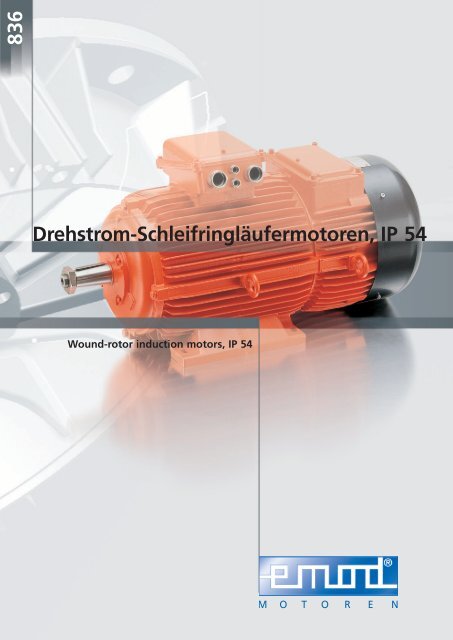
<strong>836</strong><br />
<strong>Drehstrom</strong>-Schleifringläufermotoren, <strong>IP</strong> <strong>54</strong><br />
Wound-rotor induction motors, <strong>IP</strong> <strong>54</strong>
Katalog <strong>836</strong> / 09 / Ausgabe 2009<br />
Lieferbedingungen<br />
Unseren Lieferungen und Leistungen liegen unsere<br />
Verkaufs- und Lieferbedingungen sowie die allgemeinen<br />
Lieferbedingungen für Erzeugnisse und Leistungen der<br />
Elektroindustrie zugrunde.<br />
Änderungen der in der Liste angegebenen technischen<br />
Daten sowie Maße und Gewichte bleiben vorbehalten.<br />
Reklamationen können nur innerhalb 8 Tagen nach<br />
Empfang der Ware berücksichtigt werden.<br />
Catalogue <strong>836</strong> / 09 / Edition 2009<br />
Conditions of sale and delivery<br />
Our supplies and services are subject to our own<br />
conditions of sale and delivery and the general<br />
conditions of supply and delivery for the products and<br />
services of the electrical industry.<br />
The technical data, dimensions and weights given in<br />
this catalogue are subject to change without notice.<br />
Any claims must be made within 8 days of the receipt<br />
of goods.<br />
Preise<br />
Unsere Preise gelten ab Werk, ausschließlich Verpackung,<br />
zuzüglich der gesetzlich vorgeschriebenen Mehrwertsteuer.<br />
Verpackung wird nicht zurückgenommen.<br />
Preisänderungen bleiben vorbehalten. Der Berechnung<br />
werden jeweils die am Tage der Lieferung gültigen<br />
Preise zugrunde gelegt.<br />
Prices<br />
The prices quoted are ex-works, not including packing,<br />
plus value added tax at the current rate.<br />
Packing materials are non-returnable.<br />
The right is reserved to modify prices at any time. The<br />
prices charged are those ruling on the day of despatch.<br />
Kupferzuschläge / Copper surcharge<br />
Kupferpreis lt. DEL-Notiz / Kupferzuschlag /<br />
Copper price<br />
Price increase<br />
€/100 kg %<br />
231,– bis 281,– 1,20%<br />
282,– bis 332,– 2,50%<br />
333,– bis 383,– 3,50%<br />
384,– bis 435,– 4,50%<br />
436,– bis 486,– 5,50%<br />
487,– bis 537,– 6,50%<br />
538,– bis 588,– 7,50%<br />
589,– bis 639,– 8,50%<br />
640,– bis 690,– 9,50%<br />
EMOD MOTOREN <strong>GmbH</strong><br />
Elektromotorenfabrik<br />
Hausanschrift / Address:<br />
36364 Bad Salzschlirf · Germany · Zur Kuppe 1 · Fon: + 49 66 48 51-0 · Fax: + 49664851-143<br />
info@emod-motoren.de · www.emod-motoren.de<br />
Postfachadresse / Postbox:<br />
36361 Bad Salzschlirf · Germany · Postfach / Postbox 240
Inhaltsverzeichnis / Katalog <strong>836</strong> / 09 / Ausgabe 2009<br />
Contents / Catalogue <strong>836</strong> / 09 / Edition 2009<br />
· 3·<br />
Seite<br />
Page<br />
Allgemeine technische Erläuterungen 3 – 17<br />
General technical information<br />
Leistungstabellen 18 – 23<br />
Rated output<br />
Maßtabellen 24 – 29<br />
Dimension sheets<br />
Bremsmotoren • Allgemeine technische Informationen 30 – 31<br />
Brake motors • General technical information<br />
Bremsmotoren • Maßtabellen 32 – 33<br />
Brake motors • Dimension sheets<br />
Lieferbare Flansche 34<br />
Flanges available
Technische Erläuterungen<br />
Technical data<br />
Normen und Vorschriften<br />
Die <strong>Drehstrom</strong>-Schleifringläufermotoren entsprechen<br />
den einschlägigen Normen und Vorschriften.<br />
Insbesondere werden folgende erwähnt:<br />
Standards and specifications<br />
The three-phase slipring motors comply with the<br />
relevant standards and specification.<br />
Particularly we refer to the following:<br />
Titel DIN / EN IEC<br />
Drehende elektrische Maschinen. Bemessung und Betriebsverhalten DIN EN 60 034-1 IEC 60 034-1<br />
Rotating electrical machines. Rating and performance<br />
Einteilung der Schutzarten DIN EN 60 034-5 IEC 60 034-5<br />
Classification of degree of protection<br />
Einteilung der Kühlverfahren (IC-Code) DIN EN 60 034-6 IEC 60 034-6<br />
Classification of cooling methods<br />
Bezeichnung für Bauform und Aufstellung (IM-Code) DIN EN 60 034-7 IEC 60 034-7<br />
Classification of construction and mounting<br />
· 4·<br />
Anschlussbezeichnung und Drehsinn DIN EN 6003-8 IEC 60 034-8<br />
Terminal markings and direction of rotating<br />
Mechanische Schwingungen bestimmter Maschinen mit Achshöhe 56 und größer DIN EN 60 034-14 IEC 60 034-14<br />
Mechanical vibration of certain machines with shaft heights 56 and higher<br />
<strong>Drehstrom</strong>asynchronmotoren für den Allgemeingebrauch mit standardisierten DIN 50 374 IEC 60 072-1<br />
Abmessungen und Leistungen – Baugrößen 56 bis 315 und Flanschgrößen 65 bis 740<br />
General purpose three-phase induction motors having standard dimensions and<br />
outputs – Frame numbers 56 to 315 and flange numbers 65 to 740
Mechanische Ausführung<br />
Mechanical design<br />
Schutzarten<br />
Alle <strong>Motoren</strong> sind in der Schutzart <strong>IP</strong> <strong>54</strong> und die<br />
Anschlusskästen in der Schutzart <strong>IP</strong> 55 nach<br />
DIN EN 60 034-5 ausgeführt.<br />
Die Schleifringläufermotoren sind entsprechend der<br />
Norm für die Aufstellung in staubiger und feuchter<br />
Umgebung geeignet.<br />
Bei Aufstellung im Freien sind die <strong>Motoren</strong> vor<br />
intensiver Sonneneinstrahlung zu schützen.<br />
<strong>Motoren</strong> mit Wellenende nach oben müssen vom<br />
Anwender vor Eindringen von Wasser entlang der<br />
Welle geschützt werden.<br />
Höhere Schutzarten auf Anfrage lieferbar.<br />
Degree of protection<br />
The motors have a degree of protection <strong>IP</strong> <strong>54</strong> and the<br />
terminal boxes have a degree of protection <strong>IP</strong> 55<br />
according to DIN EN 60 034-5.<br />
According to the standards the slipring motors<br />
are suitable for installation in dusty and moist<br />
environments.<br />
When installed in the open air, the motors must be<br />
protected against intensive insolation.<br />
Vertical motors with shaft end upward should be<br />
protected by the end-user against the seeping-in of<br />
water along the shaft end.<br />
On request increased degree of protection available.<br />
Kondenswasserablauflöcher<br />
Die katalogmäßigen Schleifringläufermotoren in der<br />
Schutzart <strong>IP</strong> <strong>54</strong> haben keine Kondenswasserablauflöcher.<br />
Condensate drain-holes<br />
Slipring motors listed in the catalogue with degree of<br />
protection <strong>IP</strong> <strong>54</strong> have no condensate drain-holes.<br />
· 5·<br />
Bei Aufstellung im Freien, extremen klimatischen<br />
Verhältnissen oder Aussetzbetrieb sind die <strong>Motoren</strong><br />
durch Kondensatbildung gefährdet.<br />
Auf besonderen Wunsch können Kondenswasserablauflöcher<br />
an der tiefsten Stelle des Motors<br />
angebracht werden.<br />
Bei Lieferung der <strong>Motoren</strong> sind diese mit Verschlussstopfen<br />
versehen.<br />
Die Lage der Löcher richtet sich nach Einbaulage des<br />
Motors und muss bei der Bestellung genau angegeben<br />
werden.<br />
Bei Flanschmotoren mit Wellenende nach oben können<br />
auf Wunsch Wasserablauföffnungen in den Flanschhals<br />
eingebracht werden.<br />
In case of installation in open air, extreme climatic<br />
conditions or intermittent loading, the motors are<br />
endangered by the formation of condensation.<br />
On special request condensate drain-holes can be<br />
drilled at the lowest point of the motor.<br />
The motors have caps fitted to the condensate<br />
drain-holes at delivery.<br />
The position of the holes depends on the mounting of<br />
the motor and must be indicated in the order.<br />
On request it is possible to make a water drain-hole in<br />
the flange neck on vertical flange motors with shaft<br />
end upward.<br />
Schutzdach<br />
Bei vertikaler Aufstellung mit Welle nach unten kann<br />
auf Wunsch die Luftansaugöffnung durch ein Schutzdach<br />
gegen das Hineinfallen von Fremdkörpern<br />
geschützt werden.<br />
Protective canopy<br />
When installed vertically with the shaft downward,<br />
the air intake can be protected on request with a<br />
protective canopy against fall-in of foreign bodies.<br />
Kühlung und Belüftung<br />
Die Schleifringläufermotoren haben Eigenventilatoren,<br />
die unabhängig von der Drehrichtung des Motors<br />
kühlen (Kühlart IC 411 nach DIN EN 60 034-6).<br />
Cooling and ventilation<br />
The slipring-motor integral fans are cooling the motor<br />
independent of the direction of rotation (type of<br />
cooling IC 411 according to DIN EN 60 034-6).
Stillstandsheizung<br />
Bei Schleifringläufermotoren, die starken Temperaturschwankungen<br />
oder extremen klimatischen Verhältnissen<br />
ausgesetzt sind, ist die Motorwicklung durch Kondensatbildung<br />
oder Betauung gefährdet. Als Option<br />
kann eine eingebaute Stillstandsheizung die Motorwicklung<br />
nach dem Abschalten erwärmen und einen<br />
Feuchtigkeitsniederschlag im Motorinneren verhindern.<br />
Während des Betriebes darf die Stillstandsheizung<br />
nicht eingeschaltet werden.<br />
Anti-condensation heaters<br />
The windings of slipring motors subjected to extreme<br />
temperature fluctuations or severe climatic conditions<br />
are endangered by the formation of condensation or<br />
moisture.<br />
Optional it is possible to use anti-condensation heaters<br />
inside the motor to heat up the winding after shutdown<br />
and prevent the formation of moisture inside<br />
the motor.<br />
The anti-condensation heaters must not be switched on<br />
while the motor is running.<br />
Baugröße / Frame size Heizleistung / Heating capacity Anschlussspannung / Supply voltage<br />
W<br />
V<br />
100 – 112 50 230 110<br />
132 – 200 100 230 110<br />
225 – 315 150 230 110<br />
355 200 230 110<br />
· 6·<br />
Motorbauteile / Motor components<br />
Gehäuse Lagerschild / Flansch Anschlusskasten<br />
Frame End shields / Flange Terminal box<br />
Baugröße Aluminium- Grauguss Aluminium- Grauguss Aluminium- Grauguss<br />
Frame size legierung legierung legierung<br />
Aluminium alloy Grey cast iron Aluminium alloy Grey cast iron Aluminium alloy Grey cast iron<br />
100 – 112 – – <br />
132 – – <br />
160 – 355 – – – <br />
Standardausführung / Standard version<br />
Auf Anfrage lieferbar / Available on request<br />
Die Motorfüße sind bei den Baugrößen 100 – 315<br />
angegossen und bei Baugröße 355 angeschraubt.<br />
For motor sizes 100 – 315 the motor feet are cast on the<br />
frame and for motor size 355 bolted to the frame.<br />
Eigenlüfter<br />
Baugrößen 100 – 315 Kunststoff<br />
Baugrößen 355 Aluminiumlegierung<br />
Kunststofflüfter sind bei Umgebungstemperaturen von<br />
–25°C bis +60°C einsetzbar.<br />
Lüfter aus Aluminiumlegierung sind für alle Baugrößen<br />
gegen Mehrpreis lieferbar.<br />
Integral fans<br />
Frame sizes 100 – 315 plastic<br />
Frame sizes 355 aluminium alloy<br />
Integral fans of plastic can be used from an ambient<br />
temperature –25°C up to +60°C.<br />
Fans of aluminium alloy are available for all motor<br />
sizes at extra price.<br />
Lüfterhaube<br />
Baugrößen 100 – 355 aus Stahlblech<br />
Fan cover<br />
Frame sizes 100 – 355 of sheet steel
Lagerung<br />
Die Schleifringläufermotoren der Baugrößen 100 – 200<br />
haben dauergeschmierte Wälzlager.<br />
Ab der Baugröße 225 haben die <strong>Motoren</strong><br />
Nachschmiereinrichtung mit Fettmengenregler.<br />
Nachschmierfrist, Fettmenge und Fettqualität sind<br />
durch ein Zusatzschild am Motor angegeben.<br />
Verstärkte Lagerausführung A-Seite für Antriebe mit<br />
erhöhten Querkräften oder Nachschmiereinrichtung<br />
sind ab Baugröße 100 gegen Mehrpreis lieferbar.<br />
Die <strong>Motoren</strong> der Baugrößen 100 – 355 haben<br />
serienmäßig Festlager auf der B-Seite.<br />
Die Lager sind durch axial wirkende Federn<br />
vorgespannt.<br />
Bearings<br />
The slipring motors with frame sizes 100 – 200 have<br />
permanent grease-lubricated anti-friction bearings.<br />
From frame size 225 the motors have regreasing<br />
devices with grease quantity control.<br />
Regreasing intervals, quantity of grease and grade of<br />
grease are marked on an auxiliary plate on the motor.<br />
Heavy-duty bearing arrangements at drive-end for<br />
increased radial load or regreasing devices are from<br />
frame size 100 available at extra price.<br />
The motors with frame sizes 100 – 355 have the<br />
locating bearing at non-drive-end.<br />
The bearings are pre-loaded with axial springs.<br />
· 7·<br />
Lagerzuordnung / Bearing and frame size<br />
Baugröße<br />
Frame size<br />
Polzahl<br />
No. of poles<br />
AS-Lager<br />
DE-bearing<br />
BS-Lager<br />
NDE-bearing<br />
Fettmenge<br />
Quantity of grease<br />
100 ≥ 4 6206 2Z 6206 2Z – –<br />
Nachschmiermenge<br />
Quantity of regrease<br />
112 ≥ 4 6306 2Z C3 6306 2Z C3 – –<br />
132 ≥ 4 6308 Z C3 6307 C3 25 / 18 –<br />
160 ≥ 4 6309 C3 6309 C3 30 –<br />
180 ≥ 4 6311 C3 6311 C3 50 –<br />
200 ≥ 4 6313 C3 6313 C3 85 –<br />
225 ≥ 4 6313 C3 6313 C3 85 18<br />
250 ≥ 4 6314 C3 6314 C3 100 21<br />
280 ≥ 4 6316 C3 6316 C3 150 27<br />
315 ≥ 4 6317 C3 6317 C3 180 30<br />
355 ≥ 4 6322 C3 6322 C3 350 35<br />
Verstärkte Lagerung A-seitig ist auf Anfrage lieferbar / Heavy-duty bearings at drive-end are available on request
Schmierstoffe / Lubricants<br />
Betriebsbedingungen Wärmeklasse Wälzlagerfett / Einsatzbereich<br />
Operating conditions Insulating class Bearing grease / Service range<br />
Normal<br />
Standard<br />
Hohe Temperaturen,<br />
extreme Betriebsbedingungen<br />
High temperatures,<br />
extreme operating conditions<br />
Tiefe Temperaturen<br />
Low temperatures<br />
F<br />
H<br />
F<br />
Baugrößen 100 – 112, Lithiumseifenfett, –30°C bis +140°C<br />
Baugrößen 132 – 355, Barium-Komplex, –20°C bis +140°C<br />
Frame sizes 100 – 112, lithium-based grease, –30°C bis +140°C<br />
Frame sizes 132 – 355, barium complex, –20°C bis +140°C<br />
Hochtemperatur- und Langzeitschmierstoff,<br />
vollsynthetisches Grundöl, –20°C bis +180°C<br />
High-temperature and long-term grease,<br />
fully synthetic base oil, –20°C bis +180°C<br />
Tieftemperaturschmierstoff, Barium-Komplex, –50°C bis +150°C<br />
Low-temperature grease, barium complex, –50°C bis +150°C<br />
· 8·<br />
Nachschmierfristen / Regreasing intervals<br />
Baugröße / Frame size<br />
Motor-Drehzahlen / Motor speed<br />
1500 min -1 1000 min -1 750 min -1<br />
225 7800 h 10400 h 12400 h<br />
250 7200 h 9800 h 11400 h<br />
280 6200 h 9100 h 10400 h<br />
315 5900 h 9100 h 9800 h<br />
355 4900 h 6500 h 8500 h<br />
Die genannten Nachschmierfristen verkürzen sich bei<br />
erhöhter thermischer Beanspruchung, wechselnder<br />
Belastung oder einem hohen Verschmutzungsgrad.<br />
Nachschmierung oder Erneuerung des Schmierstoffes<br />
darf nur mit einer gleichartigen Fettsorte erfolgen<br />
(gleicher Konsistenzgeber ist wichtig).<br />
The regreasing intervals should be shorter at increased<br />
thermal stress, alternating load or a high level of<br />
pollution.<br />
The same type of grease must be used when<br />
regreasing or renewing the lubricant completely<br />
(identical consistency is important).<br />
Transportsicherung<br />
Schleifringläufermotoren mit verstärkter Lagerung<br />
durch eingebaute Rollenlager sind durch Erschütterungen<br />
während des Transports und der Lagerung gefährdet.<br />
Die eingebaute Lagerverriegelung schützt vor<br />
Beschädigung der Lager.<br />
Vor Inbetriebnahme ist die Transportsicherung zu<br />
entfernen.<br />
Shipping brace<br />
Slipring motors with heavy-duty bearing arrangements<br />
by roller bearings are endangered by vibration during<br />
transport and storage.<br />
The built-in shipping brace protects the bearings from<br />
damage.<br />
The shipping brace must be removed before starting<br />
up the motor.
Zulässige Radialbelastung<br />
Die Werte gelten für die in diesem Katalog<br />
zugeordneten Lager und antriebsseitigen Wellenenden<br />
für eine rechnerische Lebensdauer von L h = 20 000 h<br />
ohne axiale Belastung.<br />
Kraftangriffspunkt ist Maß X.<br />
Permissible radial load<br />
The values apply to the listed bearing size and<br />
drive-end shafts listed in this catalogue for a calculated<br />
lifetime of L h = 20 000 h without axial load.<br />
Point of load action is dimension X.<br />
F r<br />
X<br />
· 9·<br />
Baugröße Angriffspunkt Zulässige Radialbelastung F r bei F a = 0<br />
Frame size Point of action Permissible radial load F r at F a = 0<br />
X n = 1500 min -1 n = 1000 min -1 n = 750 min -1<br />
mm N N N<br />
100 L 30 450 490 490<br />
112 M 30 630 700 810<br />
132 M 40 1700 1900 2200<br />
160 M<br />
2050 2300 2600<br />
55<br />
160 L 2100 2350 2650<br />
180 L 55 3 150 3600 4000<br />
200 L 55 3 700 4300 4750<br />
225 M 70 3 450 4000 4400<br />
250 M 70 3 900 4550 5000<br />
280 SM<br />
4500 5250 5900<br />
70<br />
280 M 4500 5250 5900<br />
315 SM/M<br />
3900 4550 5200<br />
85<br />
315 L 3700 4350 5000<br />
355 L 85 5900 6900 8000
Zulässige Axialbelastung<br />
Die Werte gelten für die in diesem Katalog zugeordneten<br />
Lager und antriebsseitigen Wellenenden für<br />
eine rechnerische Lebensdauer von L h = 20 000 h ohne<br />
radiale Belastung bei horizontaler und vertikaler<br />
Aufstellung.<br />
Permissible axial load<br />
The values apply to the listed bearing size and driveend<br />
shafts listed in this catalogue for a calculated lifetime<br />
of L h = 20 000 h without radial load for horizontal<br />
and vertical mounting.<br />
Baugröße Zulässige Axialbelastung F a bei F r = 0<br />
Frame size Permissible axial load F a at F r = 0<br />
n = 1500 min -1 n = 1000 min -1 n = 750 min -1<br />
Aufstellung / Mounting Aufstellung / Mounting Aufstellung / Mounting<br />
Belastung nach / Load direction Belastung nach / Load direction Belastung nach / Load direction<br />
horizontal vertikal horizontal vertikal horizontal vertikal<br />
horizontal vertical horizontal vertical horizontal vertical<br />
unten oben unten oben unten oben<br />
downward upward downward upward downward upward<br />
N N N N N N N N N<br />
100 L 260 200 320 330 250 410 390 330 450<br />
112 M 460 370 550 560 450 670 630 510 750<br />
132 M 1400 1200 1700 1600 1400 1950 1800 1550 2100<br />
· 10 ·<br />
160 M 2300 1900 2700 2600 2200 3050 2900 2500 3350<br />
160 L 2300 1850 2750 2600 2150 3100 2900 2450 4000<br />
180 L 3300 2700 3950 3800 3200 4450 4200 3600 4850<br />
200 L 4000 3200 4800 4600 3800 5500 5000 4250 5550<br />
225 M 3900 2850 5100 4500 3350 5750 5000 3850 6200<br />
250 M 4400 3000 5800 5000 3650 6500 5600 4200 7100<br />
280 SM 5000 3300 7000 5800 4100 7900 6450 4700 8500<br />
280 M 5000 3050 7250 5800 3750 8150 6450 4400 8750<br />
315 SM/M 4800 1100 8900 5550 1600 10000 6200 2250 10650<br />
315 L 4600 900 5300 1350 11200 5900 1400 11800<br />
355 L 6900 1400 14100 8350 1700 15600 9200 2200 17100
Wellenende<br />
Die Wellenenden sind zylindrisch und die Abmessungen<br />
sind den Baugrößen und Leistungen entsprechend<br />
DIN EN 50 347 zugeordnet.<br />
Motorwellen aus rost-, säure- und hitzebeständigen<br />
Stählen sowie kundenspezifische Wellenabmessungen<br />
sind auf Anfrage lieferbar.<br />
Kegelige Wellenenden mit Steigung 1:10 nach DIN 1448<br />
bzw. SEB 841 101-70 sind gegen Mehrpreis lieferbar<br />
Serienmäßig werden die Wellenenden der Schleifringläufermotoren<br />
Baugröße 100 – 355 mit einem Zentriergewinde<br />
nach DIN 332-2, Form D, geliefert.<br />
Shaft extension<br />
Depending on the frame size and rated output the<br />
cylindrical shaft extensions accord with the standards<br />
DIN EN 50 347.<br />
Motor shafts of stainless, acid- and heat-resistant steel,<br />
or dimensions according to customers specification are<br />
available on request.<br />
Conical motor shafts with a pitch 1:10 according to<br />
DIN 1448 and SEB 841 101-70 are available at extra price.<br />
Slipring motors of frame sizes 100 – 355 are supplied<br />
with a tapped centre hole according to DIN 332-2,<br />
form D as a standard fitting.<br />
AS-Wellenende / DE shaft extension<br />
Durchmesser / Diameter<br />
mm<br />
Zentriergewinde / Centre hole thread<br />
mm<br />
> 24 – 30 M 10<br />
> 30 – 38 M 12<br />
> 38 – 50 M 16<br />
> 50 – 85 M 20<br />
> 85 – 130 M 24<br />
· 11 ·<br />
Die Schleifringläufermotoren werden mit eingelegter<br />
Passfeder nach DIN 6 885-1, Form A, geliefert.<br />
Ein zweites Wellenende ist auf Bestellung lieferbar.<br />
Die maximalen Abmessungen sind in den Maßblättern<br />
angegeben.<br />
Die übertragbare Leistung und die zulässigen<br />
Querkräfte für das zweite Wellenende auf Anfrage.<br />
The slipring motors are supplied with inserted<br />
featherkey according to DIN 6 885-1, form A.<br />
A second shaft extension is available to order.<br />
The maximum dimensions are listed in the dimension<br />
sheets.<br />
Information about the transmittable power and<br />
permissible radial load of the second shaft extension<br />
on request.<br />
Auswuchtung<br />
Bei allen Schleifringläufermotoren sind die Läufer mit<br />
eingelegter halber Passfeder dynamisch ausgewuchtet<br />
nach DIN ISO 8 821.<br />
Antriebselemente wie Riemenscheiben, Kupplungen<br />
und Pumpenräder müssen ebenfalls mit eingelegter<br />
halber Passfeder dynamisch ausgewuchtet werden.<br />
Es ist darauf zu achten, dass die Nabenlänge und die<br />
Länge der Passfedernut übereinstimmen, damit keine<br />
zusätzliche Restunwucht entsteht.<br />
Auf besonderen Wunsch ist auch Vollkeilwuchtung<br />
möglich.<br />
Die Art der Passfederwuchtung ist entsprechend der<br />
Norm auf der Stirnseite der Antriebswelle gekennzeichnet.<br />
Balancing<br />
The rotors of all slipring motors are balanced<br />
dynamically with a half featherkey fitted according to<br />
DIN ISO 8 821.<br />
Drive elements, such as belt pulleys, couplings or pump<br />
impeller wheels, must also be dynamically balanced<br />
with a half featherkey fitted.<br />
It is important to pay attention, that the length of the<br />
hub is the same as the length of the featherkey to<br />
avoid an additional residual unbalance.<br />
The balancing with full featherkey is possible on<br />
request.<br />
The kind of balancing is marked at the front of the<br />
shaft according to the standard.
Mechanische Laufruhe<br />
Das Schwingverhalten der <strong>Motoren</strong> entspricht auf<br />
Grund der Auswuchtung und Rundlauftoleranzen der<br />
Schwinggrößenstufe A nach DIN EN 60 034-14.<br />
Bei besonderen Anforderungen an die mechanische<br />
Laufruhe können <strong>Motoren</strong> in schwingungsarmer<br />
Ausführung geliefert werden.<br />
Running smoothness<br />
Depending on the balancing and the runout tolerances<br />
the vibration characteristics corresponds to vibration<br />
severity rating A according to DIN EN 60 034-14.<br />
For special requirements to the running smoothness,<br />
precision-balanced motors are available.<br />
Schwinggrößenstufe Aufstellung Grenzwert der Schwingsgrößen abhängig von der Baugröße<br />
Vibration severity rating mounting Limit values of vibration severity to frame size<br />
56 – 132 160–280 315–450<br />
S eff V eff a eff S eff V eff a eff S eff V eff a eff<br />
µm mm/s m/s 2 µm mm/s m/s 2 µm mm/s m/s 2<br />
A<br />
B<br />
freie Aufhängung<br />
freely suspended<br />
freie Aufhängung<br />
freely suspended<br />
25 1,6 2,5 35 2,2 3,5 45 2,8 4,4<br />
11 0,7 1,1 18 1,1 1,7 29 21,8 2,8<br />
· 12 ·<br />
Wellenabdichtung / Getriebeanbau<br />
Für den Anbau an Getriebe können die Schleifringläufermotoren<br />
auf Wunsch mit Radialdichtring ausgerüstet<br />
werden.<br />
Die Schmierung der Dichtstelle durch Sprühöl oder<br />
Ölnebel muss gewährleistet sein.<br />
Es darf kein Druck auf den Dichtring wirken.<br />
Für eine Vielzahl von Getriebefabrikaten stehen auf<br />
Anfrage Sonderwellen und Sonderflansche für den<br />
direkten Getriebeanbau zur Verfügung.<br />
Shaft sealing / Gearbox mounting<br />
For mounting to gearboxes the slipring motors are<br />
available with a radial shaft seal on request.<br />
Lubricant of the sealing location must be assured by<br />
spray oil or oil mist.<br />
Pressure to the sealing ring is not allowed.<br />
For a lot of different gearbox types special shafts and<br />
flanges are available on request, for the direct mounting<br />
to the gearbox.
Klemmenkasten<br />
Bei allen Baugrößen sind die Klemmenkästen um 90º<br />
drehbar.<br />
Die Klemmenkastenlage bei Normalausführung ist auf<br />
die Antriebswelle gesehen rechts (0º) und die Kabeleinführung<br />
Richtung A.<br />
Abweichende Klemmenkastenlage und Kabeleinführungslage<br />
bitte bei Bestellung angeben.<br />
Terminal box<br />
For all frame sizes the terminal boxes are rotatable<br />
through 90º.<br />
The terminal box alignment in standard version is to<br />
the right (0º) when looking at drive end. Standard<br />
cable inlet to direction A.<br />
Please indicate deviations of terminal box alignment<br />
and cable inlet direction by order.<br />
Klemmenkastenlage<br />
Terminal box position<br />
270°<br />
Lage der Kabeleinführung<br />
Position of cable inlet<br />
180° 0°<br />
C<br />
B<br />
D<br />
A<br />
90°<br />
Kabeleinführung A (Standard)<br />
Cable inlet A (standard)<br />
· 13 ·<br />
Leitungseinführung und Anschlussklemmen / Cable inlets and terminals<br />
Baugröße Leitungseinführungsgewinde Anschlussgewinde Max. Strom je Klemmenbolzen<br />
Frame size Cable inlet thread Terminal thread Max. current on terminal<br />
100 – 112 2 x M25 x 1,5 9 x M5 25 A<br />
132 2 x M25 x 1,5 + 1 x M16 x 1,5 9 x M6 63 A<br />
160–180 2 x M40 x 1,5 + 2 x M16 x 1,5 9 x M8 100 A<br />
200–250 2 x M50 x 1,5 + 2 x M16 x 1,5 9 x M10 160 A<br />
280 –315 M* 2 x M63 x 1,5 + 2 x M16 x 1,5 9 x M12 / M16 250 A / 315 A<br />
315 L–355* 2 x M72 x 2,0 + 2 x M16 x 1,5 9 x M20 400 A<br />
* Klemmenkasten mit abschraubbarer Kabeleinführungsplatte auf Anfrage lieferbar.<br />
Terminal box with unscrewable cable entry plate available on request.<br />
Die Klemmenkastenzuordnung gilt nur für<br />
Bemessungsspannungen ≥ 400 V (ab Baugröße 280<br />
nur für Y-∆-Einschaltung).<br />
Wird die zulässige Stromstärke für die Klemmenbolzen<br />
überschritten, so sind parallele Zuleitungen erforderlich<br />
(12 Klemmen).<br />
Die Lieferung der <strong>Motoren</strong> erfolgt ohne<br />
Kabelverschraubung.<br />
Bis zur Baugröße 250 werden entsprechend der<br />
Betriebsschaltung eingelegte Verbindungsbrücken<br />
mitgeliefert.<br />
The relation of terminal boxes is only valid at<br />
rated voltage ≥ 400V (from frame size 280 only for<br />
star-delta-starting).<br />
If the permissible terminal current load is exceeded,<br />
therefore parallel cables are required (12 terminals).<br />
The cable glands are not included in the motor<br />
delivery.<br />
Up to frame size 250 the terminal links according to<br />
the operating connection are included in the delivery.
Anstrich / Painting<br />
Anstrich / Schichtdicke Eignung für Klimagruppe nach DIN IEC 721, Teil 2-1<br />
Painting / Coat thickness Suitable for climate group to DIN IEC 721, part 2-1<br />
Normalanstrich Grundierung / Primer : ≥ 20 µm Moderate<br />
Standard coat Deckanstrich/ Top coat : ≥ 35 µm<br />
Nitro-Combi-Decklack<br />
Innenraum- und Freiluftaufstellung<br />
Nitrocellulose combination finish<br />
For indoor and outdoor installation<br />
Sonderanstrich SA1 Grundierung / Primer : ≥ 20 µm Worldwide<br />
Special coat SA1 Zwischenanstrich / Sealer : ≥ 50 µm<br />
Epoxid-Zwischenanstrich RAL 1002<br />
Freiluftaufstellung, Einwirkung von Seewasseratmosphäre,<br />
Epoxy resin sealer RAL 1002<br />
Industriegasen und sauren Atmosphären<br />
Deckanstrich / Top coat : ≥ 40 µm For outdoor installation, for marine atmosphere,<br />
2-Komponenten-Polyurethan-Anstrich<br />
industrial gases and acid atmospheres<br />
Two-component polyurethane coat<br />
Alle <strong>Motoren</strong> werden standardmäßig mit<br />
Normalanstrich in Farbton RAL 7031 geliefert.<br />
Andere Farbtöne und Anstriche auf Anfrage.<br />
In standard the motors are delivered with the<br />
standard coating in colour RAL 7031.<br />
Other colours or coatings on request.<br />
· 14 ·<br />
Elektrische Ausführung<br />
Die in den Auswahltabellen angegebenen Bemessungsleistungen<br />
und Betriebswerte gelten für die angegebenen<br />
Betriebsarten nach DIN EN 60 034-1 bei einer<br />
Bemessungsfrequenz von 50 Hz, einer Kühlmitteltemperatur<br />
von max. 40 °C und einer Aufstellungshöhe<br />
bis 1000 m über NN.<br />
Die Betriebsdaten gelten mit den Toleranzen nach<br />
DIN EN 60 034-1 für die angegebene Bemessungsspannung.<br />
Electrical design<br />
The rated output and data listed in this catalogue<br />
apply to the listed operating modes according to<br />
DIN EN 60 034-1 at rated frequency 50Hz, at an<br />
ambient temperature of 40°C and at a site altitude<br />
from up to 1000 m above sea level.<br />
The rated data with the tolerances according to<br />
DIN EN 60 034-1 apply to the listed rated voltage.<br />
Toleranzen nach DIN EN 60 034-1 / Tolerances according to DIN EN 60 034-1<br />
Wirkungsgrad Leistungsfaktor Schlupf Anzugsstrom Anzugsmoment Kippmoment<br />
Efficiency Power factor Slip Starting current Starting torque Breakdown torque<br />
η cos ϕ s I A M A M K<br />
P 2 ≤ 50 kW: – 0,15 (1-η) – (1–cos ϕ) / 6<br />
P 2 > 50 kW: – 0,10 (1-η) min. 0,02; max. 0,07 ± 20% + 20% –15% bis +20% –10%
Bemessungsspannung und Frequenz<br />
Die <strong>Drehstrom</strong>-Schleifringläufermotoren werden für<br />
folgende Bemessungsspannungen geliefert:<br />
3AC, 50 Hz – 400 V, 500 V, 690 V<br />
3AC, 60 Hz – 440 V, 460 V<br />
Andere Bemessungsspannungen und Frequenzen sind<br />
gegen Mehrpreis lieferbar.<br />
Nach DIN EN 60 034-1 gilt für <strong>Motoren</strong> eine<br />
Spannungstoleranz von ±5% (Bereich A).<br />
Voltage and frequency<br />
The three-phase slipring motors are available with the<br />
following rated voltages:<br />
3AC, 50Hz – 400V, 500V, 690V<br />
3AC, 60Hz – 440V, 460V<br />
Other rated voltages and frequencies are available at<br />
extra price.<br />
According to DIN EN 60 034-1 the voltage tolerance of<br />
the motors is ±5% (section A).<br />
Kühlmitteltemperatur, Aufstellungshöhe<br />
Werden die Schleifringläufermotoren mit Kühlmitteltemperaturen<br />
abweichend von 40 ºC oder in Aufstellungshöhen<br />
größer 1000 m über NN eingesetzt, so ist die<br />
Bemessungsleistung mit den Faktoren der nachstehenden<br />
Tabelle zu korrigieren.<br />
Ambient temperature, site altitude<br />
For slipring motors operating in ambient temperatures<br />
other than 40ºC or at altitudes more than 1000 m<br />
above sea level, the rated output must be corrected<br />
with the factors of the following table.<br />
· 15 ·<br />
Aufstellungshöhe über NN<br />
Altitude above sea level<br />
Kühlmitteltemperatur / Ambient temperature<br />
< 30 ºC 30 – 40 ºC 45 ºC 50 ºC 55 ºC 60 ºC<br />
1000 m 1,07 1,00 0,96 0,92 0,87 0,82<br />
1500 m 1,04 0,97 0,93 0,89 0,84 0,79<br />
2000 m 1,00 0,94 0,90 0,86 0,82 0,77<br />
2500 m 0,96 0,90 0,86 0,83 0,78 0,74<br />
3000 m 0,92 0,86 0,82 0,79 0,75 0,70<br />
3500 m 0,88 0,82 0,79 0,75 0,71 0,67<br />
4000 m 0,82 0,77 0,74 0,71 0,67 0,63<br />
Ständerwicklung<br />
In der Normalausführung sind die Schleifringläufermotoren<br />
in Wärmeklasse „F“ ausgeführt.<br />
Die Isolierung der <strong>Motoren</strong> ist tropenfest.<br />
Verstärkter Tropen- und Feuchtschutz ist gegen<br />
Mehrpreis lieferbar.<br />
Für erhöhte Kühlmitteltemperaturen oder<br />
Wärmebeanspruchung durch hohe Schalthäufigkeiten<br />
ist ein Isolationssystem der Wärmeklasse „H“ lieferbar.<br />
Stator winding<br />
In standard version the stator and rotor winding is of<br />
insulating class “F”.<br />
The insulating of the motors is tropic-proof.<br />
Increased tropic- and moisture-proof insulating is<br />
available at extra price.<br />
An isolation system of insulating class “H” is available<br />
for increased ambient temperature or thermal stress<br />
depending on a high number of operatings per hour.
Motorschutz<br />
Bei stromabhängigem Motorschutz muss der Schutzschalter<br />
auf den am Leistungsschild angegebenen<br />
Nennstrom eingestellt werden.<br />
Bei Schalthäufigkeit, Kurzzeitbetrieb, Kühlmittelausfall<br />
oder großen Temperaturschwankungen ist der Motorschutz<br />
nur mit direkter Temperaturüberwachung sicher<br />
wirksam. Hierzu bieten sich auf Wunsch folgende<br />
Möglichkeiten an:<br />
• Temperaturschalter als Öffner<br />
Bei Erreichen der Grenztemperatur öffnet dieser<br />
selbsttätig den Hilfsstromkreis und schaltet erst<br />
nach wesentlicher Temperaturänderung wieder ein.<br />
Schaltleistung: bei Wechselspannung 250 V 1,6 A.<br />
• Kaltleiterschutz<br />
Die eingebauten Kaltleiter werden in Verbindung<br />
mit einem Auslösegerät betrieben. Bei Erreichen<br />
der Grenztemperatur ändert der Kaltleiterfühler<br />
sprunghaft seinen Widerstand. In Verbindung mit<br />
dem Auslösegerät wird diese Wirkung zur Über-<br />
Motor protection<br />
For current-sensitive motor protection, the protective<br />
switch has to be set to the rated current given on the<br />
name plate.<br />
This motor protection is inadequate for high number<br />
of operations, short-time operation, coolant breakdown<br />
or for fluctuations in coolant temperature.<br />
In these cases motors should be protected by direct<br />
temperature protection (extra price):<br />
• Thermal protector switch<br />
When reaching the limiting temperature, the switch<br />
opens the control circuit. The NC-switch closes the<br />
circuit when the temperature decreases essential.<br />
Contact rating: 1,6 amps for 250VAC.<br />
• Thermistor protection<br />
The embedded temperature sensors are able to work<br />
only in conjunction with a tripping unit. When<br />
reaching the limiting temperature, the thermistor<br />
changes its resistance almost instantaneously. This<br />
action is utilized in conjunction with the tripping<br />
· 16 ·<br />
wachung der Motortemperatur ausgenutzt.<br />
Das im Gerät eingebaute Relais verfügt über einen<br />
Umschaltkontakt, dessen Öffner und Schließer für<br />
die Steuerung benutzt werden können.<br />
Vorteil: Schutzeinrichtung überwacht sich selbst;<br />
geringe Schalttoleranz; schnelles Wiedereinschalten<br />
des Antriebes.<br />
• Messung der Wicklungs- oder Lagertemperatur<br />
Durch den Einbau von Platin-Temperaturfühlern<br />
PT 100 oder KTY-Fühlern sind die Temperaturen in<br />
der Motorwicklung oder an der Lagerung direkt<br />
messbar.<br />
Die Anschlüsse der Temperaturüberwachung sind<br />
standardmäßig auf eine Klemmenleiste im Hauptklemmenkasten<br />
geführt.<br />
Auf Wunsch kann ein separater Klemmenkasten für die<br />
Zusatzeinrichtungen angebracht werden.<br />
unit to monitor motor temperature. The relay<br />
incorporated in the device has a change-over<br />
contact, in which the contacts can be used for the<br />
control system.<br />
Advantages: The protection system is self-monitoring;<br />
low switching tolerance; quick reconnection of<br />
the drive.<br />
• Measuring of winding or bearing temperatures<br />
The temperature of the motor winding or bearings<br />
can be directly measured by incorporated temperature<br />
sensors PT 100 or KTY-sensors.<br />
In standard the connection of the temperature<br />
protection is with a terminal block inside the main<br />
terminal box.<br />
On request the connection in a separate mounted<br />
terminal box is possible.
Bürsten, Bürstenhalter, Schleifringe<br />
Alle Schleifringläufermotoren sind ohne Bürstenabhebevorrichtung<br />
ausgeführt.<br />
Die Schleifringe aus Gussbronze sind auf der B-Seite in<br />
einem topfförmigen Lagerschild untergebracht. Dieses<br />
Schleifringgehäuse hat für die Bürsten eine große Wartungsöffnung,<br />
die durch einen Deckel aus Grauguss<br />
verschlossen ist.<br />
Dichtungen aus hochelastischem Gummi verhindern<br />
das Eindringen von Wasser und Staub.<br />
Das Schleifringgehäuse kann auch nachträglich am<br />
Aufstellungsort um 90° gedreht werden. Der Bürstenapparat<br />
wird mitgedreht, sodass die Zugänglichkeit zu<br />
den Bürsten erhalten bleibt.<br />
Die Doppelschenkelbürstenhalter sind zu einem<br />
Bürstenblock zusammengefasst, der als Ganzes aus der<br />
Maschine herausgenommen werden kann.<br />
Ab Baugröße 180 ist der Wickelraum gegen das<br />
Eindringen von Bürstenstaub durch eine rotierende<br />
Dichtscheibe mit Spaltdichtung abgedichtet.<br />
Brushes, brush-holder, sliprings<br />
The slipring motors are without a brush lifting<br />
mechanism.<br />
The sliprings of cast bronze are mounted at the<br />
non-drive-end in a canned end-shield. This slipring<br />
case has a big servicing opening with a cover of<br />
grey cast iron.<br />
Seals of high-flexible rubber sealing prevent the<br />
penetration of water and dust.<br />
The slipring case is afterwards rotatable through 90° at<br />
the installation place of the motor. The brush-holders<br />
also rotate with the slipring case, so that the entrance<br />
to the brushes remains.<br />
The double-leg brush-holders are put together to a<br />
brush unit, which can be removed as a whole out of<br />
the motor frame.<br />
From frame size 180 the windings are sealed against<br />
brush dust with a rotatable sealing disc with sealing<br />
gap.<br />
· 17 ·
<strong>Drehstrom</strong>-<br />
Schleifringläufermotoren<br />
1500 min -1 50 Hz<br />
Schutzart <strong>IP</strong> <strong>54</strong><br />
Oberflächengekühlt<br />
Three-phase<br />
slipring motors<br />
1500min -1 50Hz<br />
Degree of protection <strong>IP</strong> <strong>54</strong><br />
Fan-cooled<br />
Baugröße<br />
Frame size<br />
Bemessungsleistung S3 – 40 %<br />
Rated output S3 – 40%<br />
Bemessungsdrehzahl<br />
Rated speed<br />
Bemessungsstrom bei 400 V<br />
Rated current at 400V<br />
Läuferstillstandsspannung<br />
Secondary open-circuit voltage<br />
Läufernennstrom<br />
Rotor current<br />
Bemessungsmoment<br />
Rated torque<br />
Kippmoment zu Bemessungsmoment<br />
Breakdown torque to rated torque<br />
Trägheitsmoment J<br />
Moment of inertia J<br />
Gewicht<br />
Weight<br />
· 18 ·<br />
kW min -1 A V A Nm M K /M N kgm 2 kg<br />
100 L / 4 a 2,0 1290 5,0 85 17 14,9 2,6 0,006 40<br />
112 M / 4 3,0 1390 6,7 110 18 21,5 3,2 0,012 48<br />
112 M / 4 a 4,0 1350 9,5 140 19 28,5 3,0 0,013 50<br />
132 MK / 4 5,0 1390 11,4 140 25 34 3,5 0,024 69<br />
132 M / 4 6,3 1410 13,3 160 25 43 3,5 0,032 80<br />
132 M / 4 a 7,0 1390 16,4 180 29 52 3,2 0,035 96<br />
160 M / 4 10 1425 22,5 180 36 57 3,2 0,062 138<br />
160 L / 4 14,5 1435 33 260 35 97 3,7 0,083 150<br />
180 L / 4 20 1450 43 270 46 133 3,3 0,1<strong>54</strong> 215<br />
200 LK / 4 24 1445 47 230 66 159 3,2 0,200 245<br />
200 L / 4 29 1445 55 275 66 192 3,4 0,240 260<br />
225 M / 4 39 1445 75 330 73 258 3,0 0,474 385<br />
250 MK / 4 48 1450 92 195 152 316 3,0 0,610 430<br />
250 M / 4 58 1450 110 235 151 382 3,1 0,736 460<br />
280 SM / 4 75 1450 140 240 190 495 3,0 1,22 600<br />
280 M / 4 95 1460 180 310 190 620 3,0 1,46 680<br />
315 SM / 4 115 1460 215 310 220 750 3,0 2,12 880<br />
315 M / 4 140 1460 260 375 220 915 3,0 2,<strong>54</strong> 990<br />
315 M / 4 a 165 1460 300 450 220 1080 3,0 3,25 1310<br />
315 L / 4 200 1470 370 550 220 1300 3,3 4,2 1420<br />
315 L / 4 a 225 1470 415 620 220 1460 3,1 4,8 1830<br />
315 L / 4 b 275 1470 510 620 270 1780 3,0 5,4 1980<br />
355 L / 4 400 1475 710 710 335 2590 3,0 12 2880<br />
355 L / 4 440 1470 780 710 370 2860 3,0 13 3100<br />
355 L / 4 a 500 1470 876 710 420 3250 3,1 15 3300<br />
Größere Leistungen und andere Läuferstillstandsspannungen auf Anfrage / Increased output and other secondary open-circuit voltage on request
<strong>Drehstrom</strong>-<br />
Schleifringläufermotoren<br />
1500 min -1 50 Hz<br />
Schutzart <strong>IP</strong> <strong>54</strong><br />
Oberflächengekühlt<br />
Bemessungsleistung und Bemessungsmoment<br />
bei Aussetzbetrieb S3–<br />
Three-phase<br />
slipring motors<br />
1500min -1 50Hz<br />
Degree of protection <strong>IP</strong> <strong>54</strong><br />
Fan-cooled<br />
Rated output and rated torque<br />
at intermittent periodic duty S3–<br />
Baugröße<br />
Frame size<br />
Bemessungsleistung<br />
Rated output<br />
Bemessungsmoment<br />
Rated torque<br />
Bemessungsleistung<br />
Rated output<br />
Bemessungsmoment<br />
Rated torque<br />
Bemessungsleistung<br />
Rated output<br />
Bemessungsmoment<br />
Rated torque<br />
Bemessungsleistung<br />
Rated output<br />
Bemessungsmoment<br />
Rated torque<br />
Bemessungsleistung<br />
Rated output<br />
Bemessungsmoment<br />
Rated torque<br />
Betriebsart S3 Betriebsart S3 Betriebsart S3 Betriebsart S3 Betriebsart S3<br />
100 % 60 % 40 % 25 % 15 %<br />
Operating mode S3 Operating mode S3 Operating mode S3 Operating mode S3 Operating mode S3<br />
100% 60% 40% 25% 15%<br />
kW Nm kW Nm kW Nm kW Nm kW Nm<br />
100 L / 4 a 1,5 10,5 1,8 12,9 2,0 14,9 2,3 17,7 2,5 19,8<br />
112 M / 4 2,2 15,2 2,6 18,3 3,0 21,5 3,3 24 3,7 27,5<br />
112 M / 4 a 3,0 20,5 3,5 24,5 4,0 28,5 4,5 32,5 5,0 36,5<br />
132 MK / 4 4,0 27 4,5 30,5 5,0 34 5,7 40 6,8 48<br />
132 M / 4 4,8 32 5,3 35,5 6,3 43 7,0 48 8,0 55<br />
132 M / 4 a 5,5 37 6,6 45 7,5 52 8,7 61 9,5 67<br />
160 M / 4 7,5 50 8,5 57 10 57 11 75 13 89<br />
160 L / 4 11 72 12,5 83 14,5 97 17 111 19,5 132<br />
180 L / 4 15 94 17,5 116 20 133 23 1<strong>54</strong> 27 182<br />
200 LK / 4 19 121 21 138 24 159 28 186 33 221<br />
200 L / 4 22 145 25 165 29 192 34 226 40 267<br />
225 M / 4 30 195 34 222 39 258 45 296 53 350<br />
250 MK / 4 37 240 42 275 48 316 55 360 65 430<br />
250 M / 4 45 290 51 335 58 382 68 445 80 530<br />
280 SM / 4 60 390 68 440 75 495 90 590 105 690<br />
280 M / 4 75 485 85 550 95 620 110 715 132 860<br />
315 SM / 4 90 580 100 650 115 750 132 860 160 1040<br />
315 M / 4 110 710 125 810 140 915 160 1040 190 1470<br />
315 M / 4 a 132 852 150 970 165 1080 190 1230 225 1460<br />
315 L / 4 160 1 025 180 1 160 200 1 300 230 1 500 270 1 775<br />
315 L / 4 a 180 1 150 200 1 290 225 1 460 260 1 700 300 1 970<br />
315 L / 4 b 220 1 410 250 1 610 275 1 780 315 2 060 375 2 470<br />
355 L / 4 315 2 020 355 2 290 400 2 590 450 2 940 530 3 490<br />
355 L / 4 a 355 2 270 400 2 580 440 2 860 500 3 270 600 3 950<br />
355 L / 4 b 400 2 560 450 2 900 500 3 250 570 3 720 680 4 470<br />
· 19 ·
<strong>Drehstrom</strong>-<br />
Schleifringläufermotoren<br />
1000 min -1 50 Hz<br />
Schutzart <strong>IP</strong> <strong>54</strong><br />
Oberflächengekühlt<br />
Three-phase<br />
slipring motors<br />
1000min -1 50Hz<br />
Degree of protection <strong>IP</strong> <strong>54</strong><br />
Fan-cooled<br />
Baugröße<br />
Frame size<br />
Bemessungsleistung S3 – 40 %<br />
Rated output S3 – 40%<br />
Bemessungsdrehzahl<br />
Rated speed<br />
Bemessungsstrom bei 400 V<br />
Rated current at 400V<br />
Läuferstillstandsspannung<br />
Secondary open-circuit voltage<br />
Läufernennstrom<br />
Rotor current<br />
Bemessungsmoment<br />
Rated torque<br />
Kippmoment zu Bemessungsmoment<br />
Breakdown torque to rated torque<br />
Trägheitsmoment J<br />
Moment of inertia J<br />
Gewicht<br />
Weight<br />
· 20 ·<br />
kW min -1 A V A Nm M K /M N kgm 2 kg<br />
100 L / 6 a 1,5 900 5,5 80 12 15,9 3,1 0,010 40<br />
112 M / 6 2,0 900 6,4 80 16 21 3,2 0,018 48<br />
112 M / 6 a 3,0 910 9,2 115 18 33 2,8 0,018 48<br />
132 MK / 6 4,0 900 12 110 26 43 2,9 0,032 69<br />
132 M / 6 4,5 920 13,5 120 26 48 3,3 0,038 80<br />
132 M / 6 a 5,5 910 15,8 140 27 58 2,8 0,046 86<br />
160 M / 6 7,0 940 18 180 26 72 3,1 0,094 138<br />
160 L / 6 10 940 24 260 27 102 2,8 0,128 150<br />
180 L / 6 15 950 34 230 41 151 2,9 0,193 215<br />
200 L / 6 20 955 42 255 49 200 3,0 0,245 245<br />
225 M / 6 25 960 51 250 62 249 2,9 0,736 285<br />
225 M / 6 30 965 61 290 64 297 2,9 0,736 385<br />
250 MK / 6 40 965 79 140 175 395 2,9 0,84 430<br />
250 M / 6 50 965 98 175 175 495 2,9 1,01 460<br />
280 SM / 6 63 975 120 190 205 615 3,0 1,48 600<br />
280 M / 6 75 975 140 235 200 739 3,1 1,78 680<br />
315 SM / 6 100 980 185 260 240 980 3,0 2,63 880<br />
315 M / 6 120 980 220 310 240 1170 3,0 3,08 990<br />
315 M / 6 a 140 980 255 365 240 1365 3,0 4,17 1310<br />
315 L / 6 160 980 290 420 240 1 560 3,1 4,8 1 420<br />
315 L / 6 a 200 980 360 520 240 1 950 3,0 6,3 1 830<br />
315 L / 6 b 235 980 425 610 240 2 290 3,0 7,6 1 980<br />
355 L / 6 250 985 470 630 240 2 420 3,1 15 2 840<br />
315 L / 6 a 315 985 560 630 305 3 050 3,3 18 3 080<br />
355 L / 6 a 400 985 700 710 315 3 880 3,0 24 3 300<br />
Größere Leistungen und andere Läuferstillstandsspannungen auf Anfrage / Increased output and other secondary open-circuit voltage on request
<strong>Drehstrom</strong>-<br />
Schleifringläufermotoren<br />
1000 min -1 50 Hz<br />
Schutzart <strong>IP</strong> <strong>54</strong><br />
Oberflächengekühlt<br />
Bemessungsleistung und Bemessungsmoment<br />
bei Aussetzbetrieb S3–<br />
Three-phase<br />
slipring motors<br />
1000min -1 50Hz<br />
Degree of protection <strong>IP</strong> <strong>54</strong><br />
Fan-cooled<br />
Rated output and rated torque<br />
at intermittent periodic duty S3–<br />
Baugröße<br />
Frame size<br />
Bemessungsleistung<br />
Rated output<br />
Bemessungsmoment<br />
Rated torque<br />
Bemessungsleistung<br />
Rated output<br />
Bemessungsmoment<br />
Rated torque<br />
Bemessungsleistung<br />
Rated output<br />
Bemessungsmoment<br />
Rated torque<br />
Bemessungsleistung<br />
Rated output<br />
Bemessungsmoment<br />
Rated torque<br />
Bemessungsleistung<br />
Rated output<br />
Bemessungsmoment<br />
Rated torque<br />
Betriebsart S3 Betriebsart S3 Betriebsart S3 Betriebsart S3 Betriebsart S3<br />
100 % 60 % 40 % 25 % 15 %<br />
Operating mode S3 Operating mode S3 Operating mode S3 Operating mode S3 Operating mode S3<br />
100% 60% 40% 25% 15%<br />
kW Nm kW Nm kW Nm kW Nm kW Nm<br />
100 L / 6 a 1,1 11,4 1,3 13,6 1,5 15,9 1,7 18,5 1,8 20<br />
112 M / 6 1,5 15,7 1,8 18,9 2,0 21 2,3 25 2,5 27,5<br />
112 M / 6 a 2,2 23,5 2,6 28 3,0 33 3,3 37 3,8 43<br />
132 MK / 6 3,0 31 3,6 38 4,0 43 4,7 51 5,2 58<br />
132 M / 6 3,5 36 4,1 43 1,5 48 5,2 57 6,0 67<br />
132 M / 6 a 4,0 41 4,8 50 5,5 58 6,5 70 7,0 78<br />
160 M / 6 6,0 56 6,0 61 7,0 72 8,0 83 9,5 100<br />
160 L / 6 7,5 75 8,5 85 10 102 11,5 118 13,5 142<br />
180 L / 6 11 109 13 130 15 151 17,5 178 21 216<br />
200 L / 6 15 148 17,5 174 20 200 24 240 28 285<br />
225 M / 6 19 182 22 218 25 249 30 300 35 350<br />
225 M / 6 22 217 26 256 30 297 35 350 42 420<br />
250 MK / 6 30 295 34 335 40 395 48 480 55 550<br />
250 M / 6 37 360 42 415 50 495 60 600 70 700<br />
280 SM / 6 45 440 53 520 63 615 72 710 85 840<br />
280 M / 6 55 535 65 635 75 739 90 885 105 1040<br />
315 SM / 6 75 730 87 950 100 980 115 1130 140 1380<br />
315 M / 6 90 875 105 1020 120 170 140 1370 165 1620<br />
315 M / 6 a 110 1070 125 1210 140 1365 160 1560 190 1860<br />
315 L / 6 120 1 170 140 1 360 160 1 560 180 1 790 220 2 180<br />
315 L / 6 a 150 1 465 175 1 695 200 1 950 230 2 240 280 2 720<br />
315 L / 6 b 175 1 720 205 1 990 235 2 290 270 2 630 325 3 190<br />
355 L / 6 185 1 810 215 2 105 250 2 420 285 2 780 350 3 375<br />
355 L / 6 a 235 2 280 275 2 655 315 3 050 360 3 500 440 4 260<br />
355 L / 6 b 300 2 900 350 3 380 400 3 880 460 4 460 560 5 420<br />
· 21 ·
<strong>Drehstrom</strong>-<br />
Schleifringläufermotoren<br />
750 min -1 50 Hz<br />
Schutzart <strong>IP</strong> <strong>54</strong><br />
Oberflächengekühlt<br />
Three-phase<br />
slipring motors<br />
750min -1 50Hz<br />
Degree of protection <strong>IP</strong> <strong>54</strong><br />
Fan-cooled<br />
Baugröße<br />
Frame size<br />
Bemessungsleistung S3 – 40 %<br />
Rated output S3 – 40%<br />
Bemessungsdrehzahl<br />
Rated speed<br />
Bemessungsstrom bei 400 V<br />
Rated current at 400V<br />
Läuferstillstandsspannung<br />
Secondary open-circuit voltage<br />
Läufernennstrom<br />
Rotor current<br />
Bemessungsmoment<br />
Rated torque<br />
Kippmoment zu Bemessungsmoment<br />
Breakdown torque to rated torque<br />
Trägheitsmoment J<br />
Moment of inertia J<br />
Gewicht<br />
Weight<br />
· 22 ·<br />
kW min -1 A V A Nm M K /M N kgm 2 kg<br />
132 M / 8 2,0 660 5,6 160 8,5 29 2,5 0,039 81<br />
132 M / 8 a 3,0 665 8,3 240 8,5 43 2,5 0,0<strong>54</strong> 86<br />
160 M / 8 5,5 695 13,5 160 22 76 2,5 0,106 138<br />
160 L / 8 7,0 700 21 200 22 96 2,5 0,144 150<br />
180 L / 8 10,5 705 26 210 32 142 2,6 0,240 215<br />
200 L / 8 15 710 37 250 38 202 2,8 0,434 260<br />
225 M / 8 20 715 47 220 57 267 2,8 0,813 385<br />
225 M / 8 25 715 55 270 58 335 2,7 0,813 385<br />
250 MK / 8 30 720 64 150 124 400 2,9 1,26 430<br />
250 M / 8 40 725 86 190 130 525 2,8 1,50 460<br />
280 SM / 8 50 725 105 200 150 655 2,9 1,99 600<br />
280 M / 8 63 730 128 250 155 825 2,9 2,39 680<br />
315 SM / 8 80 730 160 285 170 1040 2,9 4,<strong>54</strong> 880<br />
315 M / 8 100 735 195 360 170 1300 2,9 6,81 990<br />
315 L / 8 130 735 255 380 240 1 620 3,0 7,6 1 830<br />
315 L / 8 a 160 735 300 470 210 2 080 3,1 8,5 1 980<br />
355 L / 8 215 735 400 620 245 2 790 3,1 18 3 080<br />
355 L / 8 a 275 735 510 710 280 3 570 3,0 24 3 300<br />
Größere Leistungen und andere Läuferstillstandsspannungen auf Anfrage / Increased output and other secondary open-circuit voltage on request
<strong>Drehstrom</strong>-<br />
Schleifringläufermotoren<br />
750 min -1 50 Hz<br />
Schutzart <strong>IP</strong> <strong>54</strong><br />
Oberflächengekühlt<br />
Bemessungsleistung und Bemessungsmoment<br />
bei Aussetzbetrieb S3–<br />
Three-phase<br />
slipring motors<br />
750min -1 50Hz<br />
Degree of protection <strong>IP</strong> <strong>54</strong><br />
Fan-cooled<br />
Rated output and rated torque<br />
at intermittent periodic duty S3–<br />
Baugröße<br />
Frame size<br />
Bemessungsleistung<br />
Rated output<br />
Bemessungsmoment<br />
Rated torque<br />
Bemessungsleistung<br />
Rated output<br />
Bemessungsmoment<br />
Rated torque<br />
Bemessungsleistung<br />
Rated output<br />
Bemessungsmoment<br />
Rated torque<br />
Bemessungsleistung<br />
Rated output<br />
Bemessungsmoment<br />
Rated torque<br />
Bemessungsleistung<br />
Rated output<br />
Bemessungsmoment<br />
Rated torque<br />
Betriebsart S3 Betriebsart S3 Betriebsart S3 Betriebsart S3 Betriebsart S3<br />
100 % 60 % 40 % 25 % 15 %<br />
Operating mode S3 Operating mode S3 Operating mode S3 Operating mode S3 Operating mode S3<br />
100% 60% 40% 25% 15%<br />
kW Nm kW Nm kW Nm kW Nm kW Nm<br />
132 M / 8 1,5 20 1,8 25 2,0 29 2,3 34 2,5 38<br />
132 M / 8 a 2,2 30 2,6 37 3,0 43 3,3 49 3,8 58<br />
160 M / 8 4,0 53 4,8 65 5,5 76 6,5 91 7,0 102<br />
160 L / 8 5,5 74 6,0 81 7,0 96 8,0 111 9,5 133<br />
180 L / 8 7,5 100 9,0 121 10,5 142 12,5 172 15 209<br />
200 L / 8 11 146 13 174 15 202 18 244 22 300<br />
225 M / 8 15 198 18 239 20 267 25 340 30 410<br />
225 M / 8 18,5 244 22 292 25 335 30 400 35 475<br />
250 MK / 8 22 290 26 340 30 400 35 470 42 565<br />
250 M / 8 27 350 32 420 40 525 48 635 55 735<br />
280 SM / 8 37 480 44 575 50 655 60 790 70 930<br />
280 M / 8 47 610 55 720 63 825 75 990 90 1190<br />
315 SM / 8 60 780 70 910 80 1040 93 1220 110 1440<br />
315 M / 8 75 970 88 1140 100 1300 115 1500 140 1830<br />
315 L / 8 97 1 210 115 1 400 130 1 620 150 1 860 180 2 265<br />
315 L / 8 a 120 1 550 140 1 810 160 2 080 185 2 390 220 2 910<br />
355 L / 8 160 2 085 185 2 425 215 2 790 250 3210 300 3 900<br />
355 L / 8 a 200 2 670 240 3 100 275 3 570 315 4 110 380 4 990<br />
· 23 ·
<strong>Drehstrom</strong>-<br />
Schleifringläufermotoren<br />
nach DIN 42 673<br />
Maßblatt Nr. <strong>836</strong>/09.001<br />
Bauform B3<br />
Three-phase<br />
slipring motors<br />
according to DIN 42 673<br />
Dimension sheet No. <strong>836</strong>/09.001<br />
Type of construction B3<br />
q<br />
k1<br />
k<br />
m1, m2, m3 n<br />
l<br />
l1<br />
u<br />
u1<br />
t<br />
o<br />
d<br />
d1<br />
t1<br />
s4<br />
s5<br />
l<br />
w1<br />
a<br />
w2<br />
l1<br />
u<br />
d6<br />
l2<br />
e<br />
l3<br />
d7<br />
u1<br />
d4<br />
d5<br />
t<br />
d2<br />
d<br />
d1<br />
d3<br />
t1<br />
· 24 ·<br />
Baugröße / Frame size 100 L 112 M 132 M 160 M 160 L 180 L 200 L 225 M 250 M 280 SM 280 M 315 SM 315 M 315 L 355 L<br />
DIN<br />
IEC<br />
a B 140 140 178 210 2<strong>54</strong> 279 305 311 349 368 419 406 457 678 930<br />
b A 160 190 216 2<strong>54</strong> 279 318 356 406 457 508 610<br />
c HA 14 12 18 24 26 30 30 35 40 50 45<br />
e BB 175 180 220 264 308 310 365 371 410 450 500 500 551 810 1100<br />
f AB 205 232 260 314 350 400 436 500 570 630 610 710<br />
g AC 198 220 260 315 350 388 433 480 <strong>54</strong>0 610 710<br />
g1 / 157 169 195 252,5 270 295 328 360 432 467 535<br />
g2 / 157 169 195 252,5 270 295 328 360 432 467 535<br />
h H 100 112 132 160 180 200 225 250 280 315 355<br />
k L 493 531,5 618 726 770 865 924 1015 1129 1289 1399 1725 2048<br />
k1 LC 559 597,5 713 866 910 1005 1064 1155 1304 1464 1574 1900 2238<br />
m1 / 49 44 108 123 145 169,5 185,5 204,5 242,5 387 463 732 925<br />
m2 / 49 44 108 123 145 169,5 185,5 204,5 242,5 387 463 732 925<br />
m3 / 110 127 108 123 145 169,5 185,5 204,5 242,5 387 463 732 925<br />
n / 107 107 140 180 180 200 200 200 285 285 355<br />
o / 107 107 140 225 225 255 255 255 350 350 427<br />
p HD 200 224 265 320 360 394 443 491 552 622 708<br />
q LD 193 200 258 323 345 369,5 395,5 444,5 482,5 539,5 614,5 777,5 886<br />
s K M10 M10 M10 M12 M12 M16 M16 M20 M20 M24 M24<br />
s1 O 2x 2x 2x 2x 2x 2x 2x 2x 2x 2x 2x<br />
M25x1,5 M25x1,5 M25x1,5 M40x1,5 M40x1,5 M50x1,5 M50x1,5 M50x1,5 M63x1,5 M63x1,5 M72x2<br />
s4 DB M10 M10 M12 M16 M16 M20 M20 M20 M20 M20 M24<br />
s5 / M10 M10 M12 M16 M16 M20 M20 M20 M20 M20 M20<br />
v / 14,5 10 – – – 20 21 13,5 20 20 –<br />
v1 / 0 10 – – – 20 21 13,5 20 20 –<br />
w1 C 63 70 89 108 120 133 149 168 190 216 255<br />
w2 CA 236 167,5 286 328 385 406 445 517 575 591 743
Passung d/d1 = ISA k6; ab Ø 55 mm ISA m6<br />
Innengewinde s4/s5 = DIN 332, Form DR<br />
Passfeder u/u1 = DIN 6 885/1<br />
s = Durchgangsbohrung für Schrauben<br />
m1 = Klemmenkasten 0° (Standard)<br />
m2 = Option Klemmenkasten 270°<br />
m3 = Option Klemmenkasten 180°<br />
k1 = Option mit 2. Wellenende<br />
Fit diameter d/d1 = ISA k6; from Ø 55mm ISA m6<br />
Internal thread s4/s5 = DIN 332, form DR<br />
Featherkey u/u1 = DIN 6 885/1<br />
s = through-holes for bolts<br />
m1 = terminal box 0° (standard)<br />
m2 = option terminal box 270°<br />
m3 = option terminal box 180°<br />
k1 = option with 2nd shaft<br />
g<br />
g1<br />
270°<br />
v1<br />
g1<br />
0°<br />
s1<br />
g2<br />
180°<br />
h<br />
c<br />
p<br />
v<br />
v<br />
s1<br />
s<br />
b<br />
f<br />
s1<br />
Option Klemmenkasten oben (270°)<br />
Option terminal box on top (270°)<br />
Option Klemmenkasten links (180°)<br />
Option terminal box left (180°)<br />
Baugröße / Frame size 100 L 112 M 132 M 160 M 160 L 180 L 200 L 225 M 250 M 280 SM 280 M 315 SM 315 M 315 L 355 L<br />
zyl. Welle AS<br />
cyl. drive-end<br />
shaft<br />
zyl. Welle BS<br />
cyl. non-driveend<br />
shaft<br />
kegl. Welle AS<br />
con. drive-end shaft<br />
kegl. Welle AS<br />
con. drive-end shaft<br />
DIN<br />
IEC<br />
d D 28 28 38 42 48 55 60 65 75 80 90<br />
i2 LE 60 60 80 110 110 110 140 140 140 170 170<br />
l E 60 60 80 110 110 110 140 140 140 170 170<br />
t GA 31 31 41 45 51,5 59 64 69 79,5 85 95<br />
u F 8 8 10 12 14 16 18 18 20 22 25<br />
d1 DA 28 28 38 42 48 55 55 60 65 70 75<br />
l1 EA 60 60 80 110 110 110 110 140 140 140 140<br />
t1 GC 31 31 41 45 51,5 59 59 64 69 74,5 79,5<br />
u1 FA 8 8 10 12 14 16 18 18 18 20 20<br />
d D – – – – 48 55 60 65 75 80 –<br />
d2 D1 – – – – 39,8 46,8 49,5 <strong>54</strong>,5 64,5 67 –<br />
d4 XE – – – – M30x2 M36x3 M42x3 M42x3 M48x3 M56x4 –<br />
d6 DB – – – – M10 M12 M16 M16 M16 M20 –<br />
l E – – – – 110 110 140 140 140 170 –<br />
l2 V – – – – 82 82 105 105 105 130 –<br />
t GA – – – – 48,9 56,4 61,4 66,4 76,4 81,2 –<br />
u F – – – – 12 14 16 16 18 20 –<br />
d1 D – – – – 48 55 55 60 65 70 –<br />
d3 D1 – – – – 39,8 46,8 46,8 49,5 <strong>54</strong>,5 59,5 –<br />
d5 XE – – – – M30x2 M36x3 M36x3 M42x3 M42x3 M48x3 –<br />
d7 DB – – – – M10 M12 M12 M16 M16 M16 –<br />
l1 E – – – – 110 110 110 140 140 140 –<br />
l3 V – – – – 82 82 82 105 105 105 –<br />
t1 GA – – – – 48,9 56,4 56,4 61,4 66,4 71,4 –<br />
u1 F – – – – 12 14 14 16 16 18 –<br />
· 25 ·
<strong>Drehstrom</strong>-<br />
Schleifringläufermotoren<br />
nach DIN 42 677<br />
Maßblatt Nr. <strong>836</strong>/09.002<br />
Bauform B5<br />
Three-phase<br />
slipring motors<br />
according to DIN 42 677<br />
Dimension sheet No. <strong>836</strong>/09.002<br />
Type of construction B5<br />
q<br />
k1<br />
k<br />
f1<br />
m<br />
n<br />
l1<br />
u<br />
l<br />
u1<br />
t<br />
a1<br />
b1<br />
o<br />
d<br />
d1<br />
t1<br />
s5<br />
u<br />
s4<br />
d6<br />
i2<br />
l<br />
l2<br />
c1<br />
l1<br />
l3<br />
d7<br />
u1<br />
d4<br />
d5<br />
t<br />
d2<br />
d<br />
d1<br />
d3<br />
t1<br />
· 26 ·<br />
Baugröße / Frame size 100 L 112 M 132 M 160 M 160 L 180 L 200 L 225 M 250 M 280 SM 280 M 315 SM 315 M 315 L 355 L<br />
zyl. Welle AS<br />
cyl. drive-end<br />
shaft<br />
DIN<br />
IEC<br />
a1 P 250 250 300 350 350 400 450 550 550 660 800<br />
b1 N 180 180 230 250 250 300 350 450 450 550 680<br />
c1 LA 16 16 20 20 20 20 20 22 22 25 25<br />
e1 M 215 215 265 300 300 350 400 500 500 600 740<br />
f1 T 4 4 4 5 5 5 5 5 5 6 6<br />
x L 4 4 4 4 4 4 8 8 8 8 8<br />
s2 S 14 14 14 18 18 18 18 18 18 22 22<br />
g AC 198 220 260 315 350 388 433 480 <strong>54</strong>0 610 710<br />
g1 / 157 169 195 252,5 270 295 328 360 432 467 535<br />
k L 493 531,5 618 726 770 865 924 1015 1129 1289 1399 1725 2048<br />
k1 LC 559 597,5 713 866 910 1005 1064 1155 1304 1464 1574 1900 2238<br />
m / 49 44 108 123 145 169,5 185,5 204,5 242,5 387 463 732 925<br />
n / 107 107 140 180 180 200 200 200 285 285 355<br />
o / 107 107 140 225 225 255 255 255 350 350 427<br />
q LD 193 200 258 323 345 369,5 395,5 444,5 482,5 539,5 614,5 777,5 886<br />
s1 O 2x 2x 2x 2x 2x 2x 2x 2x 2x 2x 2x<br />
M25x1,5 M25x1,5 M25x1,5 M40x1,5 M40x1,5 M50x1,5 M50x1,5 M50x1,5 M63x1,5 M63x1,5 M72x2<br />
s4 DB M10 M10 M12 M16 M16 M20 M20 M20 M20 M20 M24<br />
s5 / M10 M10 M12 M16 M16 M20 M20 M20 M20 M20 M20<br />
v / 14,5 10 – – – 20 21 13,5 20 20 –<br />
d D 28 28 38 42 48 55 60 65 75 80 90<br />
i2 LE 60 60 80 110 110 110 140 140 140 170 170<br />
l E 60 60 80 110 110 110 140 140 140 170 170<br />
t GA 31 31 41 45 51,5 59 64 69 79,5 85 95<br />
u F 8 8 10 12 14 16 18 18 20 22 25
e1<br />
Passung d/d1 = ISA k6; ab Ø 55 mm ISA m6<br />
Passung b1<br />
= ISA j6; ab Ø a1 350 mm ISA h6<br />
Innengewinde s4/s5 = DIN 332, Form DR<br />
Passfeder u/u1 = DIN 6 885/1<br />
k1 = Option mit 2. Wellenende<br />
Fit diameter d/d1 = ISA k6; from Ø 55mm ISA m6<br />
Fit diameter b1 = ISA j6; from Ø a1 350 mm ISA h6<br />
Internal thread s4/s5 = DIN 332, form DR<br />
Featherkey u/u1 = DIN 6 885/1<br />
k1 = option with 2nd shaft<br />
g1<br />
g<br />
Lochzahl x<br />
s2<br />
4 x 90°<br />
v<br />
45°<br />
22°<br />
30°<br />
8 x 45°<br />
s1<br />
Baugröße / Frame size 100 L 112 M 132 M 160 M 160 L 180 L 200 L 225 M 250 M 280 SM 280 M 315 SM 315 M 315 L 355 L<br />
DIN IEC<br />
d1 DA 28 28 38 42 48 55 55 60 65 70 75<br />
l1 EA 60 60 80 110 110 110 110 140 140 140 140<br />
t1 GC 31 31 41 45 51,5 59 59 64 69 74,5 79,5<br />
u1 FA 8 8 10 12 14 16 18 18 18 20 20<br />
d D – – – – 48 55 60 65 75 80 –<br />
d2 D 1 – – – – 39,8 46,8 49,5 <strong>54</strong>,5 64,5 67 –<br />
d4 XE – – – – M30x2 M36x3 M42x3 M42x3 M48x3 M56x4 –<br />
d6 DB – – – – M10 M12 M16 M16 M16 M20 –<br />
l E – – – – 110 110 140 140 140 170 –<br />
l2 V – – – – 82 82 105 105 105 130 –<br />
t GA – – – – 48,9 56,4 61,4 66,4 76,4 81,2 –<br />
u F – – – – 12 14 16 16 18 20 –<br />
d1 D – – – – 48 55 55 60 65 70 –<br />
d3 D1 – – – – 39,8 46,8 46,8 49,5 <strong>54</strong>,5 59,5 –<br />
d5 XE – – – – M30x2 M36x3 M36x3 M42x3 M42x3 M48x3 –<br />
d7 DB – – – – M10 M12 M12 M16 M16 M16 –<br />
l1 E – – – – 110 110 110 140 140 140 –<br />
l3 V – – – – 82 82 82 105 105 105 –<br />
t1 GA – – – – 48,9 56,4 56,4 61,4 66,4 71,4 –<br />
u1 F – – – – 12 14 14 16 16 18 –<br />
zyl. Welle BS<br />
cyl. non-driveend<br />
shaft<br />
kegl. Welle AS<br />
con. drive-end shaft<br />
kegl. Welle AS<br />
con. drive-end shaft<br />
· 27 ·<br />
Andere lieferbare Flansche siehe Maßblatt Nr. <strong>836</strong>/01.005 / Other available flanges see dimension sheet No.<strong>836</strong>/01.005
<strong>Drehstrom</strong>-<br />
Schleifringläufermotoren<br />
nach DIN 42 673 und<br />
DIN 42 677<br />
Maßblatt Nr. <strong>836</strong>/09.003<br />
Bauform B3/B5<br />
Three-phase<br />
slipring motors<br />
according to DIN 42 673<br />
and DIN 42 677<br />
Dimension sheet No. <strong>836</strong>/09.003<br />
Type of construction B3/B5<br />
k1<br />
q<br />
k<br />
f1<br />
m1, m2, m3 n<br />
l1<br />
u<br />
l<br />
u1<br />
t<br />
a1<br />
b1<br />
o<br />
d<br />
d2<br />
t1<br />
s5<br />
s4<br />
i2<br />
c1<br />
e<br />
u<br />
d6<br />
l<br />
l2<br />
w1<br />
a<br />
w2<br />
l1<br />
l3<br />
d7<br />
u1<br />
d4<br />
d5<br />
t<br />
d2<br />
d<br />
d1<br />
d3<br />
t1<br />
· 28 ·<br />
Baugröße / Frame size 100 L 112 M 132 M 160 M 160 L 180 L 200 L 225 M 250 M 280 SM 280 M 315 SM 315 M 315 L 355 L<br />
Fußmaße<br />
Feet dimensions<br />
Flanschmaße<br />
Flange dimensions<br />
DIN<br />
IEC<br />
a B 140 140 178 210 2<strong>54</strong> 279 305 311 349 368 419 406 457 670 930<br />
b A 160 190 216 2<strong>54</strong> 279 318 356 406 457 508 610<br />
c HA 14 12 18 24 26 30 30 35 40 50 45<br />
e BB 175 180 220 264 308 310 365 371 410 450 500 500 551 810 1100<br />
f AB 205 232 260 314 350 400 436 500 570 630 610 710<br />
a1 P 250 250 300 350 350 400 450 550 550 660 800<br />
b1 N 180 180 230 250 250 300 350 450 450 550 680<br />
c1 LA 16 16 20 20 20 20 20 22 22 25 25<br />
e1 M 215 215 265 300 300 350 400 500 500 600 740<br />
f1 T 4 4 4 5 5 5 5 5 5 6 6<br />
x L 4 4 4 4 4 4 8 8 8 8 8<br />
s2 S 14 14 14 18 18 18 18 18 18 22 822<br />
g AC 198 220 260 315 350 388 433 480 <strong>54</strong>0 610 710<br />
g1 / 157 169 195 252,5 270 295 328 360 432 467 535<br />
g2 / 157 169 195 252,5 270 295 328 360 432 467 535<br />
h H 100 112 132 160 180 200 225 250 280 315 355<br />
k L 493 531,5 618 726 770 865 924 1015 1129 1289 1399 1725 2048<br />
k1 LC 559 597,5 713 866 910 1005 1064 1155 1304 1464 1574 1900 2238<br />
m1 / 49 44 108 123 145 169,5 185,5 204,5 242,5 387 463 732 925<br />
m2 / 49 44 108 123 145 169,5 185,5 204,5 242,5 387 463 732 925<br />
m3 / 110 127 108 123 145 169,5 185,5 204,5 242,5 387 463 732 925<br />
n / 107 107 140 180 180 200 200 200 285 285 355<br />
o / 107 107 140 225 225 255 255 255 350 350 427<br />
p HD 200 224 265 320 360 394 443 491 552 622 708<br />
q LD 193 200 258 323 345 369,5 395,5 444,5 482,5 539,5 614,5 777,5 886<br />
s K M10 M10 M10 M12 M12 M16 M16 M20 M20 M24 M24<br />
s1 O 2x 2x 2x 2x 2x 2x 2x 2x 2x 2x 2x<br />
M25x1,5 M25x1,5 M25x1,5 M40x1,5 M40x1,5 M50x1,5 M50x1,5 M50x1,5 M63x1,5 M63x1,5 M72x2<br />
s4 DB M10 M10 M12 M16 M16 M20 M20 M20 M20 M20 M24<br />
s5 / M10 M10 M12 M16 M16 M20 M20 M20 M20 M20 M20
Passung d/d1 = ISA k6; ab Ø 55 mm ISA m6<br />
Passung b1<br />
= ISA j6; ab Ø a1 350 mm ISA h6<br />
Innengewinde s4/s5 = DIN 332, Form DR<br />
Passfeder u/u1 = DIN 6 885/1<br />
s = Durchgangsbohrung für Schrauben<br />
m1 = Klemmenkasten 0° (Standard)<br />
m2 = Option Klemmenkasten 270°<br />
m3 = Option Klemmenkasten 180°<br />
k1 = Option mit 2. Wellenende<br />
Fit diameter d/d1 = ISA k6; from Ø 55mm ISA m6<br />
Fit diameter b1 = ISA j6; from Ø a1 350 mm ISA h6<br />
Internal thread s4/s5 = DIN 332, form DR<br />
Featherkey u/u1 = DIN 6 885/1<br />
s = through-holes for bolts<br />
m1 = terminal box 0° (standard)<br />
m2 = option terminal box 270°<br />
m3 = option terminal box 180°<br />
k1 = option with 2nd shaft<br />
g1<br />
Lochzahl x<br />
g<br />
e1<br />
s2<br />
270°<br />
v1<br />
g1<br />
0°<br />
s1<br />
180°<br />
v1<br />
p<br />
v<br />
v<br />
g2<br />
c<br />
s1<br />
s<br />
b<br />
f<br />
s1<br />
Option Klemmenkasten oben (270°)<br />
Option terminal box on top (270°)<br />
Option Klemmenkasten links (180°)<br />
Option terminal box left (180°)<br />
Baugröße / Frame size 100 L 112 M 132 M 160 M 160 L 180 L 200 L 225 M 250 M 280 SM 280 M 315 SM 315 M 315 L 355 L<br />
DIN IEC<br />
v / 14,5 10 – – – 20 21 13,5 20 20 –<br />
v1 / 0 10 – – – 20 21 13,5 20 20 –<br />
w1 C 63 70 89 108 120 133 149 168 190 216 255<br />
w2 CA 236 167,5 286 328 385 406 445 517 575 591 743<br />
d D 28 28 38 42 48 55 60 65 75 80 90<br />
i2 LE 60 60 80 110 110 110 140 140 140 170 170<br />
l E 60 60 80 110 110 110 140 140 140 170 170<br />
t GA 31 31 41 45 51,5 59 64 69 79,5 85 95<br />
u F 8 8 10 12 14 16 18 18 20 22 25<br />
d1 DA 28 28 38 42 48 55 55 60 65 70 75<br />
l1 EA 60 60 80 110 110 110 110 140 140 140 140<br />
t1 GC 31 31 41 45 51,5 59 59 64 69 74,5 79,5<br />
u1 FA 8 8 10 12 14 16 18 18 18 20 20<br />
d D – – – – 48 55 60 65 75 80 –<br />
d2 D 1 – – – – 39,8 46,8 49,5 <strong>54</strong>,5 64,5 67 –<br />
d4 XE – – – – M30x2 M36x3 M42x3 M42x3 M48x3 M56x4 –<br />
d6 DB – – – – M10 M12 M16 M16 M16 M20 –<br />
l E – – – – 110 110 140 140 140 170 –<br />
l2 V – – – – 82 82 105 105 105 130 –<br />
t GA – – – – 48,9 56,4 61,4 66,4 76,4 81,2 –<br />
u F – – – – 12 14 16 16 18 20 –<br />
d1 D – – – – 48 55 55 60 65 70 –<br />
d3 D 1 – – – – 39,8 46,8 46,8 49,5 <strong>54</strong>,5 59,5 –<br />
d5 XE – – – – M30x2 M36x3 M36x3 M42x3 M42x3 M48x3 –<br />
d7 DB – – – – M10 M12 M12 M16 M16 M16 –<br />
l1 E – – – – 110 110 110 140 140 140 –<br />
l3 V – – – – 82 82 82 105 105 105 –<br />
t1 GA – – – – 48,9 56,4 56,4 61,4 66,4 71,4 –<br />
u1 F – – – – 12 14 14 16 16 18 –<br />
zyl. Welle AS<br />
cyl. drive-end<br />
shaft<br />
zyl. Welle BS<br />
cyl. non-driveend<br />
shaft<br />
kegl. Welle AS<br />
con. drive-end shaft<br />
kegl. Welle AS<br />
con. drive-end shaft<br />
· 29 ·<br />
Andere lieferbare Flansche siehe Maßblatt Nr. <strong>836</strong>/01.005 / Other available flanges see dimension sheet No.<strong>836</strong>/01.005
Schleifringläufer-Bremsmotoren<br />
Die in der Liste angegebenen Schleifringläufermotoren<br />
können durch Anbau einer Federkraftbremse zu<br />
Bremsmotoren erweitert werden.<br />
Die angebaute Einscheiben-Federkraftbremse ist<br />
eine Sicherheitsbremse, die durch Federkraft bei<br />
abgeschalteter Spannung bremst.<br />
Slipring brake motors<br />
The three-phase slipring motors listed in the catalogue<br />
can be extended to become brake motors by mounting<br />
a spring-loaded brake.<br />
The mounted single-disc spring-loaded brake is a<br />
fail-safe brake acting by spring force with the voltage<br />
disconnected.<br />
1 = Ankerscheibe / Armature plate<br />
2 = Druckfedern / Compressing springs<br />
3 = Rotor / Rotor<br />
4 = Nabe / Hub<br />
5 = Welle / Shaft<br />
6 = Flansch / Flange<br />
7 = Magnetteil / Stator<br />
8 = Einstellring / Adjustment ring<br />
9 = Verstellbare Abstandsbuchse /<br />
Adjustable spacer bush<br />
· 30 ·<br />
Funktionsprinzip der Bremse<br />
Federkraftbremsen sind Einscheibenbremsen mit zwei<br />
Reibflächen. Durch eine oder mehrere Druckfedern<br />
wird im stromlosen Zustand das Bremsmoment durch<br />
Reibschluss erzeugt. Das Lösen der Bremse erfolgt<br />
elektromagnetisch.<br />
Beim Bremsvorgang wird der auf der Nabe (4) axial<br />
verschiebbare Rotor (3) durch die Druckfedern (2) über<br />
die Ankerscheibe (1) an die Gegenreibfläche (6)<br />
gedrückt. Im gebremsten Zustand ist zwischen Ankerscheibe<br />
und Magnetteil (7) der Lüftweg s lü vorhanden.<br />
Zum Lüften der Bremse wird die Spule des Magnetteils<br />
mit Gleichspannung erregt. Die entstehende Magnetkraft<br />
zieht die Ankerscheibe gegen die Federkraft an<br />
das Magnetteil. Der Rotor ist damit von der Federkraft<br />
entlastet und kann sich frei drehen.<br />
Bremsmomenteinstellung<br />
Die Bremsmotoren sind auf das in der Liste angegebene<br />
maximale Bremsmoment eingestellt.<br />
Durch Verdrehen des Einstellringes (8) verändern sich<br />
die Federkraft und das übertragbare Bremsmoment<br />
kann stufenlos reduziert werden (Ausnahme: Tachobremse).<br />
Function of the brake<br />
The spring-operated brakes are single-disc brakes with<br />
two friction surfaces. The brake torque is generated by<br />
one or several compression springs by friction. The<br />
brake is released electromagnetically.<br />
While braking, the rotor (4), which is axially movable<br />
on the hub (3), is pressed against the counter friction<br />
surface (6) via the armature plate (1) by means of the<br />
compressimg springs (2). In case of braking, an air gap<br />
s lü occurs between stator (7) and armature plate.<br />
To release the brake, the stator coil is excited by means<br />
of DC current. The magnetic force generated attracts<br />
the armature plate towards the stator against the<br />
spring force. The rotor is then released and can rotate<br />
freely.<br />
Adjustment of braking torque<br />
The brake motors are set to the maximum braking<br />
torque listed in the catalogue.<br />
The transmittable braking torque can be reduced by<br />
reducing the spring force through the adjustment<br />
ring (8) (not for tacho-generator brake).
Bremsenzuordnung<br />
Brake assignment<br />
Baugröße / Frame size<br />
Lieferbare Bremsmomente (Nm) / Available brake torques (Nm)<br />
60 100 250<br />
100 <br />
112 <br />
132 <br />
160 <br />
180 <br />
200 <br />
Bremsenzuordnung Baugrößen 225 – 355 auf Anfrage<br />
Optionen (auf Anfrage)<br />
• Handlüftung zum manuellen Lüften der Bremse<br />
• Tachobremse für Anbau von Tachogeneratoren oder<br />
Impulsgebern<br />
• Erhöhter Korrosionsschutz und Abdichtung<br />
• Lüftwegüberwachung durch Mikroschalter<br />
• Verschleißüberwachung durch Mikroschalter<br />
Anschluss<br />
Der Anschluss des Bremssystems erfolgt über einen im<br />
Klemmenkasten eingebauten Gleichrichter.<br />
Brake assignment for frame sizes 225 – 355 on request<br />
Options (on request)<br />
• Hand release for manual releasing of the brake<br />
• Tacho generator brakes for mounting a tacho<br />
generator or an encoder<br />
• Increased corrosion protection and enclosure<br />
• Air gap monitoring by microswitch<br />
• Wear monitoring by microswitch<br />
Connection<br />
The braking system is connected via a rectifier inside<br />
the main terminal box.<br />
· 31 ·<br />
Die anzulegende Wechselspannung ist auf dem<br />
Leistungsschild angegeben.<br />
Durch die getrennte Erregung kann die Bremse über<br />
eine Steuerung bei Stillstand des Motors gelüftet<br />
werden. Bei hoher Schalthäufigkeit wird dadurch das<br />
Anlaufen gegen die geschlossene Bremse verhindert,<br />
was sonst zu einem frühzeitigen Verschleiß des<br />
Bremsbelages und zu erhöhter Wicklungserwärmung<br />
des Motors führen könnte.<br />
Gleichrichtertyp<br />
Je nach Betriebs- und Spannungsverhältnissen empfiehlt<br />
es sich, einen Brückengleichrichter oder einen Einweggleichrichter<br />
einzusetzen (bei Bestellung angeben).<br />
The AC supply voltage to be applied is indicated on the<br />
motor name plate.<br />
Depending on the separate connection, the brake can<br />
be released with a control unit at motor standstill.<br />
The start against the working brake can be prevented<br />
for high permissible number of operations per hour.<br />
This safe for a premature wear of the friction faces and<br />
for an increased winding temperature of the motor.<br />
Type of rectifier<br />
Depending on the different operation conditions and<br />
voltages, it is possible to use a bridge rectifier or<br />
single-way rectifier (please indicate by order).<br />
Bemessungsspannung, Motor Wechselspannung, Gleichspannung, Gleichrichtertyp<br />
Rated voltage, motor Gleichrichteranschluss Gleichrichteranschluss Type of rectifier<br />
AC voltage, rectifier connection DC voltage, rectifier connection<br />
380 – 420 V 220 – 240 V 205 V Brücke / Bridge<br />
380 – 420 V 190 V Einweg / Single-way<br />
440 – 460 V 2<strong>54</strong> – 265 V 230 V Brücke / Bridge<br />
440 – 460 V 205 V Einweg / Single-way<br />
500 V 290 V 250 V Brücke / Bridge<br />
500 V 230 V Einweg / Single-way<br />
Andere Spannungen auf Anfrage<br />
Die Bremsen können auch für Gleichspannung 24 V oder<br />
110 V geliefert werden. Der Anschluss erfolgt dann<br />
direkt auf einer Klemmenleiste im Klemmenkasten.<br />
Other voltages on request<br />
The brakes are also available for DC voltage 24V or<br />
110V. The connection of the brake is directly on a<br />
terminal block inside the terminal box.
<strong>Drehstrom</strong>-Schleifringläufer-<br />
Bremsmotoren<br />
nach DIN 42 673<br />
Maßblatt Nr. <strong>836</strong>/09.004<br />
Bauform B3<br />
Three-phase slipring brake<br />
motors<br />
according to DIN 42 673<br />
Dimension sheet No. <strong>836</strong>/09.004<br />
Type of construction B3<br />
q<br />
k1<br />
k<br />
m1, m2, m3 n<br />
l<br />
l1<br />
u<br />
u1<br />
t<br />
o<br />
d<br />
d1<br />
t1<br />
s4<br />
s5<br />
l<br />
w1<br />
a<br />
w2<br />
l1<br />
u<br />
d6<br />
l2<br />
e<br />
l3<br />
d7<br />
u1<br />
d4<br />
d5<br />
t<br />
d2<br />
d<br />
d1<br />
d3<br />
t1<br />
· 32 ·<br />
Baugröße / Frame size 100 L 112 M 132 M 160 M 160 L 180 L 200 L<br />
Bremse /Brake (Nm) 60 60 60/100 100/250 100/250 100/250 100/250<br />
DIN IEC<br />
a B 140 140 178 210 2<strong>54</strong> 279 305<br />
b A 160 190 216 2<strong>54</strong> 279 318<br />
c HA 14 12 18 24 26 30<br />
e BB 175 180 220 264 308 310 365<br />
f AB 205 232 260 314 350 400<br />
g AC 198 220 260 315 350 388<br />
g1 / 157 169 195 252,5 270 295<br />
g2 / 157 169 195 252,5 270 295<br />
h H 100 112 132 160 180 200<br />
k L 583 627,5 727 865 909 1015 1091<br />
k1 LC 639 683,5 821 975 1019 1155 1231<br />
m1 / 49 44 108 123 145 169,5 185,5<br />
m2 / 49 44 108 123 145 169,5 185,5<br />
m3 / 110 127 108 123 145 169,5 185,5<br />
n / 107 107 140 180 180 200<br />
o / 107 107 140 225 225 255<br />
p HD 200 224 265 320 360 394<br />
q LD 193 200 258 323 345 369,5 395,5<br />
s K M10 M10 M10 M12 M12 M16<br />
s1 O 2xM25x1,5 2xM25x1,5 2xM25x1,5 2xM40x1,5 2xM40x1,5 2xM50x1,5<br />
s4 DB M10 M10 M12 M16 M16 M20<br />
s5 / M8 M8 M12 M12 M16 M16<br />
v / 14,5 10 – – – 20<br />
v1 / 0 10 – – – 20<br />
w1 C 63 70 89 108 120 133<br />
w2 CA 326 363,5 394 467 535 573
Passung d/d1 = ISA k6; ab Ø 55 mm ISA m6<br />
Innengewinde s4/s5 = DIN 332, Form DR<br />
Passfeder u/u1 = DIN 6 885/1<br />
s = Durchgangsbohrung für Schrauben<br />
m1 = Klemmenkasten 0° (Standard)<br />
m2 = Option Klemmenkasten 270°<br />
m3 = Option Klemmenkasten 180°<br />
k1 = Option mit 2. Wellenende<br />
Fit diameter d/d1 = ISA k6; from Ø 55mm ISA m6<br />
Internal thread s4/s5 = DIN 332, form DR<br />
Featherkey u/u1 = DIN 6 885/1<br />
s = through-holes for bolts<br />
m1 = terminal box 0° (standard)<br />
m2 = option terminal box 270°<br />
m3 = option terminal box 180°<br />
k1 = option with 2nd shaft<br />
g<br />
g1<br />
270°<br />
v1<br />
g1<br />
0°<br />
s1<br />
g2<br />
180°<br />
h<br />
c<br />
p<br />
v<br />
v<br />
s1<br />
s<br />
b<br />
f<br />
s1<br />
Option Klemmenkasten oben (270°)<br />
Option terminal box on top (270°)<br />
Option Klemmenkasten links (180°)<br />
Option terminal box left (180°)<br />
Baugröße / Frame size 100 L 112 M 132 M 160 M 160 L 180 L 200 L<br />
Bremse /Brake (Nm) 60 60 60/100 100/250 100/250 100/250 100/250<br />
DIN IEC<br />
· 33 ·<br />
zyl. Welle AS<br />
cyl. drive-end<br />
shaft<br />
zyl. Welle BS<br />
cyl. non-driveend<br />
shaft<br />
kegl. Welle AS<br />
con. drive-end shaft<br />
kegl. Welle AS<br />
con. drive-end shaft<br />
d D 28 28 38 42 48 55<br />
l E 60 60 80 110 110 110<br />
t GA 31 31 41 45 51,5 59<br />
u F 8 8 10 12 14 16<br />
d1 DA 24 24 32 38 42 42<br />
l1 EA 50 50 80 80 110 110<br />
t1 GC 27 27 35 41 45 45<br />
u1 FA 8 8 10 10 12 12<br />
d D – – – – 48 55<br />
d2 D 1 – – – – 39,8 46,8<br />
d4 XE – – – – M30x2 M36x3<br />
d6 DB – – – – M10 M12<br />
l E – – – – 110 110<br />
l2 V – – – – 82 82<br />
t GA – – – – 48,9 56,4<br />
u F – – – – 12 14<br />
d1 D – – – – 42 42<br />
d3 D 1 – – – – 33,8 33,8<br />
d5 XE – – – – M24x2 M24x2<br />
d7 DB – – – – M8 M8<br />
l1 E – – – – 110 110<br />
l3 V – – – – 82 82<br />
t1 GA – – – – 42,9 42,9<br />
u1 F – – – – 10 10
Lieferbare Flansche<br />
Maßblatt Nr. <strong>836</strong>/09.005<br />
Available flanges<br />
Dimension sheet No. <strong>836</strong>/09.005<br />
f1<br />
4 Schrauben<br />
4 bolts<br />
Lage der Bohrungen bei<br />
Alignment of holes for<br />
8 Schrauben<br />
8 bolts<br />
∅ a1<br />
∅ b1<br />
90°<br />
∅ e1<br />
∅ s1<br />
45°<br />
c1<br />
45°<br />
22°<br />
30’<br />
Lochzahl x<br />
No. of holes<br />
Baugröße Motor- Bauform a1 b1 c1 e1 f1 s1 x<br />
Frame size verlängerung Mounting<br />
Motor P N LA M T S<br />
extension<br />
· 34 ·<br />
100 B14 FT 115 140 95 12 115 3 M8 4<br />
*** 20 B14/B5 FT/FF 130 160 110 12 130 3.5 M8/Ø9 4<br />
B14/B5 FT/FF 165 200 130 12 165 3.5 M10/Ø11 4<br />
B14/B5 FT/FF 215 250 180 16 215 4 M12/Ø14 4<br />
112 B14 FT 115 140 95 12 115 3 M8 4<br />
*** 20 B14 FT 130 160 110 12 130 3.5 M8/Ø9 4<br />
*** 20 B14/B5 FT/FF 165 200 130 14 165 3.5 M10/Ø11 4<br />
B14/B5 FT/FF 215 250 180 16 215 4 M12/Ø14 4<br />
1) *** 20.5 B14/B5 FT/FF 265 300 230 20 265 4 M12/Ø14 4<br />
132 B14 FT 130 160 110 12 130 3.5 M8 4<br />
*** 15 B14/B5 FT/FF 165 200 130 16 165 3.5 M10/Ø11 4<br />
B14/B5 FT/FF 215 250 180 16 215 4 M12/Ø14 4<br />
B14/B5 FT/FF 265 300 230 20 265 4 M12/Ø14 4<br />
B14/B5 FT/FF 300 350 250 20 300 5 M16/Ø18 4<br />
160 *** 20 B5 FF 215 250 180 16 215 4 Ø14 4<br />
B5 FF 265 300 230 20 265 4 Ø14 4<br />
B5 FF 300 350 250 20 300 5 Ø18 4<br />
B5 FF 350 400 300 20 350 5 Ø18 4<br />
B5 FF 400 450 350 22 400 5 Ø18 8<br />
180 *** 14.5 B5 FF 265 300 230 20 265 4 Ø14 4<br />
B5 FF 300 350 250 20 300 5 Ø18 4<br />
B5 FF 350 400 300 20 350 5 Ø18 4<br />
B5 FF 400 450 350 22 400 5 Ø18 8<br />
200 *** 20 B5 FF 300 350 250 20 300 5 Ø18 4<br />
B5 FF 350 400 300 22 350 5 Ø18 4<br />
B5 FF 400 450 350 22 400 5 Ø18 8<br />
B5 FF 500 550 450 25 500 5 Ø18 8<br />
225 *** 25 B5 FF 300 350 250 20 300 5 Ø18 4<br />
*** 25 B5 FF 350 400 300 20 350 5 Ø18 4<br />
B5 FF 400 450 350 22 400 5 Ø18 8<br />
B5 FF 500 550 450 25 500 5 Ø18 8<br />
250 B5 FF 350 400 300 20 350 5 Ø18 4<br />
B5 FF 400 450 350 22 400 5 Ø18 8<br />
B5 FF 500 550 450 25 500 5 Ø18 8<br />
280 *** 20 B5 FF 400 450 350 22 400 5 Ø18 8<br />
B5 FF 500 550 450 24 500 5 Ø18 8<br />
B5 FF 600 660 550 24 600 6 Ø22 8<br />
315 *** 20 B5 FF 500 550 450 25 500 5 Ø18 8<br />
B5 FF 600 660 550 25 600 6 Ø22 8<br />
B5 FF 740 800 680 25 740 6 Ø22 8<br />
355 B5 FF 740 800 680 25 740 6 Ø22 8<br />
1) Lager 6308<br />
*** Flansche B5 nur mit verlängertem Flanschhals lieferbar.<br />
*** Flansche in B5 und B14 nur mit verlängertem Flanschhals lieferbar.<br />
Bei verlängertem Flanschhals ändern sich die Maße w1, k, k1, m und q um<br />
den angegebenen Wert.<br />
1) Bearing 6308<br />
*** In construction B5 only extended-neck flanges available.<br />
*** In construction B5 and B14 only extended-neck flanges available.<br />
With extended-neck flanges used, the listed blanks must be added to the<br />
dimensions w1, k, k1, m and q.
Baureihe 820 Einphasenmotoren<br />
Schutzart <strong>IP</strong> 55 bis 2,5 kW<br />
Type 820<br />
Single-phase motors<br />
degree of protection <strong>IP</strong> 55, up to 2.5kW<br />
Baureihe 821 <strong>Drehstrom</strong>motoren <strong>IP</strong> 55<br />
in Norm- und Sonderausführungen<br />
bis 1000 kW<br />
Baureihe 822 <strong>Drehstrom</strong>motoren <strong>IP</strong> 23<br />
in Norm- und Sonderausführungen<br />
bis 1200 kW<br />
Type 821 Three-phase motors, <strong>IP</strong> 55<br />
in standard and special configurations,<br />
up to 1000kW<br />
Type 822 Three-phase motors, <strong>IP</strong> 23<br />
in standard and special configurations,<br />
up to 1200kW<br />
Baureihe 823 Außenläufermotoren<br />
Baureihe AS<br />
Baureihe 824 Topfmotoren<br />
Schutzart <strong>IP</strong> 67 bis 6 kW<br />
Baureihe 825 Tauchmotoren<br />
Schutzart <strong>IP</strong> 68 bis 1000 kW<br />
Baureihe 826 Fahr- und Hebezeugmotoren<br />
bis 2/32-polig und regelbar<br />
Baureihe 827 Positionierantriebe<br />
mit höchster Positioniergenauigkeit<br />
Type 823<br />
Type 824<br />
Type 825<br />
Type 826<br />
Type 827<br />
External rotor motors<br />
type AS<br />
Encapsulated motors<br />
degree of protection <strong>IP</strong> 67, up to 6kW<br />
Submersible motors<br />
degree of protection <strong>IP</strong> 68, up to 1000 kW<br />
Crane and hoist drive motors<br />
with pole switching up to 2/32 poles<br />
and variable speed<br />
Positioning drives<br />
with extremely high positioning accuracy<br />
Das EMOD-Lieferprogramm<br />
Delivery program<br />
Baureihe 828 Frequenzregelbare<br />
<strong>Drehstrom</strong>motoren<br />
für 1-, 2- und 4-Quadrantenbetrieb,<br />
Schutzart <strong>IP</strong> 55 und <strong>IP</strong> 23<br />
Baureihe 829 Schiffsmotoren<br />
für Unter- und Oberdeckaufstellung,<br />
mit oder ohne Abnahme<br />
Baureihe 831 Gleichstrommotoren<br />
Schutzart <strong>IP</strong> 44<br />
Baureihe 832 Gleichstrommotoren<br />
Schutzart <strong>IP</strong> 23s<br />
Baureihe 833 Thyristorregelbare<br />
<strong>Drehstrom</strong>motoren<br />
für Antriebe mit quadratischem<br />
Gegenmomentverlauf<br />
Baureihe 834 Reluktanzmotoren<br />
mit hohen Außertrittfallmomenten<br />
Baureihe 835 <strong>Drehstrom</strong>-Servomotoren<br />
mit hohem Stillstandsmoment<br />
Baureihe <strong>836</strong> <strong>Drehstrom</strong>-Schleifringläufermotoren<br />
Schutzart <strong>IP</strong> <strong>54</strong><br />
Baureihe 837 Wassergekühlte <strong>Drehstrom</strong>motoren<br />
Leistungsbereich 0,75 bis 1000 kW<br />
Baureihe 838 Flachmotoren<br />
Drehzahlen bis 24.000 U/min<br />
Type 828<br />
Type 829<br />
Type 831<br />
Type 832<br />
Type 833<br />
Type 834<br />
Type 835<br />
Type <strong>836</strong><br />
Type 837<br />
Type 838<br />
Variable speed<br />
polyphase motors<br />
1, 2 and 4 quadrant operation,<br />
degrees of protection <strong>IP</strong> 55 and <strong>IP</strong> 23<br />
Marine motors<br />
for on-deck and below-deck applications,<br />
with and without certification<br />
DC motors<br />
degree of protection <strong>IP</strong> 44<br />
DC motors<br />
degree of protection <strong>IP</strong> 23s<br />
Variable speed motors<br />
for thyristor control<br />
especially for fan installations<br />
Reluctance motors<br />
for maintaining synchronisation<br />
at high torques<br />
AC servomotors<br />
with increased standstill torques<br />
Wound-rotor induction motors<br />
degree of protection <strong>IP</strong> <strong>54</strong><br />
Water-cooled three-phase motors<br />
rated outputs 0.75kW to 1000kW<br />
Flat motors<br />
rated speeds up to 24,000rpm
© cre art.de<br />
<strong>Motoren</strong> nach Maß<br />
EMOD MOTOREN <strong>GmbH</strong><br />
Elektromotorenfabrik<br />
36364 Bad Salzschlirf<br />
Germany<br />
Fon: + 49 66 48 51-0<br />
Fax: + 49 66 48 51-143<br />
info@emod-motoren.de<br />
www.emod-motoren.de