Amateur Horizontal Component Seismometer, with Passive Leveling ...
Amateur Horizontal Component Seismometer, with Passive Leveling ...
Amateur Horizontal Component Seismometer, with Passive Leveling ...

Create successful ePaper yourself
Turn your PDF publications into a flip-book with our unique Google optimized e-Paper software.
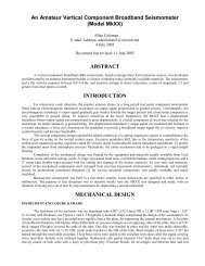
modified salvaged parts from earlier homemade seismometers, which helped to keep expenses and fabrication time to a<br />
minimum. Review Figures 1-6 for further information not disclosed in this section.<br />
Design Concept:<br />
The concept was to flexibly attach a horizontal seismometer of conventional design to a sub-plate resting on a rigid<br />
floor slab, see Figure 1. Thedisplacement transducer’s nul position was near constantly maintained, by controlling the vertical<br />
orientation ofthe pendulum’s hingeaxis in a plane vertical and parallel to the sensitive axis. Hinge axis could still be adjusted<br />
in a plane perpendicular to the sensitive axis, like a conventional horizontal design, to optimize the pendulum’s natural period<br />
by tilting the base plate <strong>with</strong> the leveling screws.<br />
A tee assembly comprised of: the pendulum, displacement transducer and feedback transducer were mounted on the<br />
central arm and a leveling float at each end of the cross arm. Tee assembly pivoted <strong>with</strong> limited movement about a pin<br />
(fulcrum point) in contact <strong>with</strong> a pedestal protruding up from the base plate, see Figure 2. Radial movement of the tee<br />
assembly, relative to the base plate, was kept in check <strong>with</strong> a flexible link between the two. Each float was partially immersed<br />
in a tank of mineral oil, <strong>with</strong> a balance tube running between the tanks. Slowly tilting the base plate, orientated <strong>with</strong> the<br />
sensitive axis, caused the oil level to lower in one tank and rise in the other, ensuring an equipotential datum plane. Floats<br />
rigidly attached to the tee assembly, prevented transducer drift by tracking the datum plane.<br />
Here is the theory behind the concept, as currently understood. Visualize a horizontal plane defined by three points on<br />
the tee assembly, the center of buoyancy (CB) for each of the two floats and the pivot pin (fulcrum point) on the central arm.<br />
On that horizontal plane lies a neutral axis, around which the tee assembly rotates, running from the pivot pin to the mid-point<br />
between the floats. In theory, the center of gravity (CG) of the entire tee assembly should fall on the neutral axis. If the CG is<br />
above the neutral axis (i.e. above the CB), the tee assembly may respond like an inverted pendulum to horizontal ground<br />
accelerations.In practice, it’s best to keep the CG a few milimeters below the neutral axis. Flexible link attached to the end of<br />
the neutral axis established the second hinge point for the tee assembly.<br />
Mineral oil was selected for the leveling fluid because: it is odorless, has a high flash point and moderate viscosity<br />
<strong>with</strong> an extremely low evaporation rate. When lightly tapping on the tee assembly, viscosity of the oil quickly damped (almost<br />
critically) any vertical oscillation. In a severe local seismic event, the oil will slosh out of the tanks and strange cross talk<br />
modes would appear in the data.<br />
Tee Assembly:<br />
The pendulum is a piece of 3/16” thick aluminum aloy sheet, approximately 140mm long. Mounted to it were the<br />
inner plates of the displacement transducer carrying the modulating signal, brass seismic masses and the feedback coil. Total<br />
equivalent seismic mass used in the transfer function was approximately 0.07 Kg, about 103mm from the pendulum’s hinge.<br />
Two pieces of 0.002” thick heat treated phosphor-bronze shim formed flexures (both in tension), connected the pendulum to<br />
the 1/8” thick alum aloy centralarm of the assembly. Mounted on the central arm were the outer signal receiver plates of the<br />
displacement transducer as well as the permanent magnet (Figure 3), part of the feedback transducer. Natural period of the<br />
pendulum was 3 seconds. An alum angle piece, bonded to the end of the central arm, held a short piece of a drill bit <strong>with</strong> a<br />
ground conical point (pivot pin) that later engaged a dimple mark, punched in the top surface of an alum bracket fastened to the<br />
base plate. Note: heavy items like feedback transducer magnet and seismic masses were deliberately placed over the pivot pin,<br />
so the floats had less weight to support.<br />
Screwed to the central arm, was the 1/16” thick alum cros arm <strong>with</strong> white colored floats, actualy plastic containers<br />
65mm OD x 58mm high. Their lids were vented and fastened to the cross bar. Center distance between floats was 270mm,<br />
center of float to pivot pin 205mm, midpoint of cross arm to the pivot pin 190mm. Each float had to displace approximately<br />
0.107 Kg of mineral oil. On a conventional horizontal seismometer, leveling screws on the base plate are used to null the<br />
displacement transducer. After oil was added to the tanks, a small trim mass was positioned in different places on one of the<br />
MkXXI’s floats to achieve the same result. Once nulled, no further trimming was necessary.<br />
Base Plate:<br />
A rigid base plate is very important to the overall stability of a conventional horizontal seismometer. Thermal stresses<br />
or the unyielding weight of the pendulum can cause plate warping, thereby creating another source for tilt noise. The beauty of<br />
utilizing a true tilt compensating design means certain structural components can be fabricated out of materials normally<br />
classified as unacceptable. In stead of a chunk of metal for the base plate, a scrap piece of PVC plastic plate 390 mm x 220 mm<br />
x 19 mm thick was selected. In theory, if the plastic warps slightly, the pendulum should not drift off center. Three screws <strong>with</strong><br />
knurled knobs used in conjunction <strong>with</strong> a bul’s eye spirit level, manually leveled the plate during initial set-ups.<br />
Flexible Link:<br />
This feature compensated for vertical and twisting motions of the tee assembly, to keep the radial position of the<br />
sensitive axis in check horizontally. Small pieces of iron nails were bonded to a piece of 1/16” diameter bras wire see Figure<br />
4. Overall length of this assembly was 75mm. Nail tips were pointed, contacting the center of a rare earth magnet attached to<br />
the cross arm at the neutral axis, and another one mounted on a post protruding from the base plate. Magnets had minimal<br />
2