S17 Longitudinal Strength of Hull Girder in Flooded ... - IACS
S17 Longitudinal Strength of Hull Girder in Flooded ... - IACS
S17 Longitudinal Strength of Hull Girder in Flooded ... - IACS

Create successful ePaper yourself
Turn your PDF publications into a flip-book with our unique Google optimized e-Paper software.
<strong>S17</strong><br />
<strong>S17</strong><br />
(cont)<br />
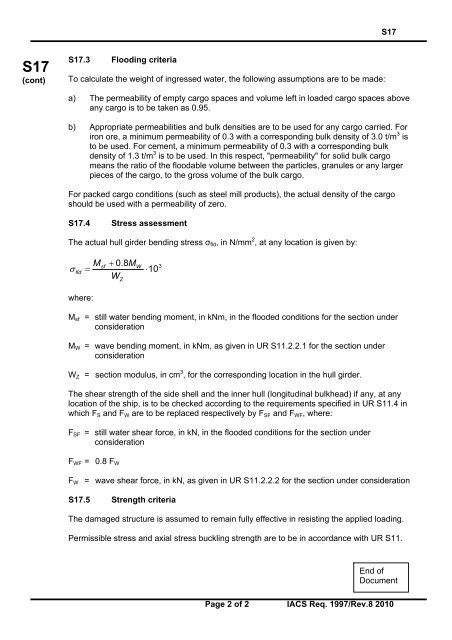
<strong>S17</strong>.3 Flood<strong>in</strong>g criteria<br />
To calculate the weight <strong>of</strong> <strong>in</strong>gressed water, the follow<strong>in</strong>g assumptions are to be made:<br />
a) The permeability <strong>of</strong> empty cargo spaces and volume left <strong>in</strong> loaded cargo spaces above<br />
any cargo is to be taken as 0.95.<br />
b) Appropriate permeabilities and bulk densities are to be used for any cargo carried. For<br />
iron ore, a m<strong>in</strong>imum permeability <strong>of</strong> 0.3 with a correspond<strong>in</strong>g bulk density <strong>of</strong> 3.0 t/m 3 is<br />
to be used. For cement, a m<strong>in</strong>imum permeability <strong>of</strong> 0.3 with a correspond<strong>in</strong>g bulk<br />
density <strong>of</strong> 1.3 t/m 3 is to be used. In this respect, "permeability" for solid bulk cargo<br />
means the ratio <strong>of</strong> the floodable volume between the particles, granules or any larger<br />
pieces <strong>of</strong> the cargo, to the gross volume <strong>of</strong> the bulk cargo.<br />
For packed cargo conditions (such as steel mill products), the actual density <strong>of</strong> the cargo<br />
should be used with a permeability <strong>of</strong> zero.<br />
<strong>S17</strong>.4 Stress assessment<br />
The actual hull girder bend<strong>in</strong>g stress σ fld , <strong>in</strong> N/mm 2 , at any location is given by:<br />
<br />
fld<br />
M<br />
<br />
sf<br />
0.8M<br />
W<br />
Z<br />
W<br />
10<br />
3<br />
where:<br />
M sf = still water bend<strong>in</strong>g moment, <strong>in</strong> kNm, <strong>in</strong> the flooded conditions for the section under<br />
consideration<br />
M W = wave bend<strong>in</strong>g moment, <strong>in</strong> kNm, as given <strong>in</strong> UR S11.2.2.1 for the section under<br />
consideration<br />
W Z = section modulus, <strong>in</strong> cm 3 , for the correspond<strong>in</strong>g location <strong>in</strong> the hull girder.<br />
The shear strength <strong>of</strong> the side shell and the <strong>in</strong>ner hull (longitud<strong>in</strong>al bulkhead) if any, at any<br />
location <strong>of</strong> the ship, is to be checked accord<strong>in</strong>g to the requirements specified <strong>in</strong> UR S11.4 <strong>in</strong><br />
which F S and F W are to be replaced respectively by F SF and F WF , where:<br />
F SF = still water shear force, <strong>in</strong> kN, <strong>in</strong> the flooded conditions for the section under<br />
consideration<br />
F WF = 0.8 F W<br />
F W = wave shear force, <strong>in</strong> kN, as given <strong>in</strong> UR S11.2.2.2 for the section under consideration<br />
<strong>S17</strong>.5 <strong>Strength</strong> criteria<br />
The damaged structure is assumed to rema<strong>in</strong> fully effective <strong>in</strong> resist<strong>in</strong>g the applied load<strong>in</strong>g.<br />
Permissible stress and axial stress buckl<strong>in</strong>g strength are to be <strong>in</strong> accordance with UR S11.<br />
End <strong>of</strong><br />
Document<br />
Page 2 <strong>of</strong> 2 <strong>IACS</strong> Req. 1997/Rev.8 2010