2012 Chevrolet Police Technical Manual (pdf) - GM Fleet
2012 Chevrolet Police Technical Manual (pdf) - GM Fleet
2012 Chevrolet Police Technical Manual (pdf) - GM Fleet

You also want an ePaper? Increase the reach of your titles
YUMPU automatically turns print PDFs into web optimized ePapers that Google loves.
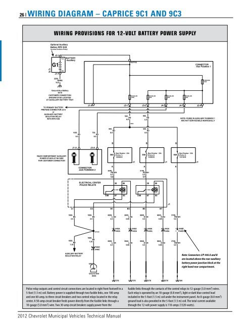
26 | wIrINg DIagram – caPrIcE 9c1 aND 9c3<br />
J1<br />
J2<br />
Ground-Aux Battery<br />
G410<br />
CUSTOMER CONNECTION<br />
GROUND STUD LOCATED<br />
AT AUXILLARY BATTERY TRAY<br />
TO PRIMARY BATTERY<br />
PREFUSE CONNECTOR J2-A<br />
or<br />
AUXILIARY BATTERY<br />
ISOLATION RELAY<br />
WITH RPO K4S<br />
REAR COMPARTMENT AUXILIARY<br />
POWER STUDS AT RH SIDE<br />
FOR CUSTOMER CONNECTION<br />
wIRING PROVISIONS FOR 12-VOLT BATTERY POwER SUPPLY<br />
Optional Auxiliary<br />
Battery RPO K4S<br />
(includes Isolation Relay)<br />
J2-1<br />
G1<br />
J1-1<br />
POS<br />
NEG<br />
2250.<br />
BARE<br />
16.0<br />
BATTERY<br />
-Auxiliary<br />
1850.<br />
BK<br />
0.5<br />
<strong>2012</strong> <strong>Chevrolet</strong> Municipal Vehicles <strong>Technical</strong> <strong>Manual</strong><br />
C1<br />
1850.<br />
BK<br />
0.5<br />
1850.<br />
BK<br />
1.25<br />
1002<br />
RD<br />
702<br />
RD<br />
8.0<br />
8.0<br />
J1-A<br />
AUXILARY BATTERY<br />
ISOLATION RELAY<br />
J2-A<br />
CONNECTOR<br />
-AUX FUSEBOX 2<br />
ELECTRICAL CENTER<br />
-POLICE RELAYS<br />
C5<br />
1850.<br />
BK<br />
1.25<br />
SA1850<br />
B P446C<br />
B J446C<br />
1850<br />
Ground Dist<br />
G405<br />
3040.<br />
RD/WH<br />
3140.<br />
RD/WH<br />
3.0<br />
3.0<br />
C3<br />
C7<br />
88<br />
502.<br />
RD<br />
8.0<br />
B<br />
Maxi Breaker - 30A<br />
30A (<strong>Police</strong> 1)<br />
12088553<br />
A<br />
B1<br />
30<br />
87<br />
1 J446A<br />
1 P446A<br />
86<br />
85<br />
B3<br />
6839.<br />
L-GN<br />
6842.<br />
L-BU<br />
3.0<br />
0.85<br />
6839.<br />
L-GN<br />
3.0<br />
<strong>Police</strong> relay outputs and control circuit connections are located in right front footwell in a<br />
5-foot (1.5 m) coil. Battery power is supplied through two fusible links, one 100-amp<br />
and one 60-amp, to three circuit breakers and two control relays located in the relay<br />
center. A 50-amp circuit breaker feeds power directly from the fusible links through a<br />
10-gauge (5.0 mm 2 ) wire. Two 30-amp circuit breakers supply power from the<br />
502.<br />
RD<br />
8.0<br />
3 J446A<br />
3 P446A<br />
6842.<br />
L-BU<br />
0.85<br />
BATPOS<br />
FUSELINK<br />
100A<br />
S502<br />
88<br />
30A<br />
A<br />
B5<br />
B<br />
Maxi Breaker - 30A<br />
(<strong>Police</strong> 2)<br />
12088553<br />
J1 J1<br />
30<br />
87<br />
6840.<br />
D-GN<br />
3.0<br />
86<br />
85<br />
B7<br />
6843.<br />
D-BU<br />
0.85<br />
J1<br />
3740.<br />
RD/WH<br />
5.0<br />
2 J446A<br />
4 J446A 1 J446B<br />
2 P446A 4 P446A 1 P446B<br />
6840.<br />
D-GN<br />
3.0<br />
1 P278 3 P278 2<br />
902.<br />
RD<br />
5.0<br />
502.<br />
RD<br />
8.0<br />
FUSELINK<br />
50A<br />
J1-A J3-1<br />
J3-2<br />
J4-2<br />
J4-1<br />
J2-A<br />
P278<br />
4<br />
P278<br />
FUSELINK<br />
60A<br />
B<br />
NOTE: FUSES IN AUXILIARY FUSEBOX 1<br />
ARE NOT SERVICEABLE INDIVIDUALLY<br />
Maxi Breaker - 50A<br />
50A (<strong>Police</strong> 3)<br />
15319848<br />
A<br />
6 43. D-BU<br />
740.<br />
RD/WH<br />
0.85<br />
5.0<br />
1<br />
P280<br />
FUSELINK<br />
60A<br />
CONNECTOR<br />
-Aux Fusebox 1<br />
J1<br />
FUSELINK<br />
140A<br />
Note: Connectors J/P 446 A and B<br />
are located above the rear auxiliary<br />
battery power junction block at the<br />
right hand rear compartment.<br />
fusible links through the contacts of the control relays to 12-gauge (3.0 mm 2 ) wires.<br />
Each relay is operated by an 18-gauge (0.8 mm 2 ), light or dark blue control lead<br />
included in the 5-foot (1.5 m) coil under the instrument panel. An 8-gauge (8.0 mm 2 )<br />
ground lead is also provided in the 5-foot (1.5 m) coil. The total current available<br />
through the 12-volt power supply is 110-amps (1320-watts).