

1uWFeBO
1uWFeBO
1uWFeBO

You also want an ePaper? Increase the reach of your titles
YUMPU automatically turns print PDFs into web optimized ePapers that Google loves.
Space Propulsion Conference 2014, SP2014_ 2968951<br />
The delta qualification has been performed successfully on<br />
an actuated NO type (worst case) pyrovalve and demonstrated<br />
the robustness of the design. The obtained results<br />
are valid for all Airbus DS types of NO pyrovalves since<br />
the internal shearing section is identical. For further details<br />
of the PV qualification status refer to [5].<br />
3.3 Propellant Latch Valve Surge and Water hammer<br />
For isolation of the main engine especially during short<br />
cruise phases dedicated high flow propellant latch valves<br />
with a 3/8" interface are used. These units are procured as<br />
off-the shelf items from a US supplier. By review of the<br />
existing qualification it was noticed that the required surge<br />
and water hammer requirements as required by Airbus DS<br />
were not yet thoroughly demonstrated and verified. For<br />
this reason a delta qualification has been performed at Airbus<br />
DS premise on a representative test item. The main<br />
goals were to demonstrate:<br />
• Priming test with latch valve open: The hydraulic<br />
shock on the inlet of the closed latch valve is typically<br />
related to the line priming of a liquid propulsion system,<br />
when normally closed pyros between propellant<br />
tank and closed latch valve are fired open. The propellant<br />
fills up the line and creates a priming shock at the<br />
end of the line.<br />
• Rapid through flow test: This case is similar to the<br />
priming case above, except that the latch valve now is<br />
open when the pyro is fired. Thus, during line filling,<br />
the flow will pass the open latch valve and priming is<br />
done up to the main engine thruster valve. Since at this<br />
stage severe forces are applied on the latch valve seat,<br />
the main target is to test whether the latch valve will<br />
stay open or not. Based on the test results, the RCS<br />
level priming sequence can be finally selected.<br />
• Re-priming test: The re-priming is related to the filling<br />
of the line downstream of the latch valve, where<br />
the line upstream of the latch valve is already filled.<br />
The re-priming is initiated by opening of the latch<br />
valve. The re-priming can be the second step of the<br />
feed line priming, where in the first step the upstream<br />
line was primed up to the closed latch valve. The repriming<br />
can also be necessary in a later mission phase<br />
(all lines already filled with propellant), when for some<br />
reason the latch valve had to be closed and the line between<br />
latch valve and thrusters had to be drained. The<br />
difference between the re-priming as a second step of<br />
the initial priming and the re-priming during a later<br />
mission phase will normally be the tank pressure,<br />
which will very likely be higher in the latter case.<br />
• Valve closure test at 0,1 kg/s flow rate: The closing<br />
of the latch valve under flow of propellant can occur<br />
when the latch valve is commanded closed during main<br />
engine operation. The latch valve commanding can be<br />
unintentionally (degraded AOCS) or intentionally (e.g.<br />
nominal thruster shut down does not work then shut<br />
down must be performed by closing of latch valve).<br />
For verification a dedicated test setup as shown in Figure<br />
3-7 has been built-up in a laboratory at Airbus DS facility<br />
Lampoldshausen. All tests were performed with deionized<br />
3AF/ESA/CNES/DLR Space Propulsion 2014,<br />
Copyright © 2014 by the authors.<br />
Published by 3AF Association Aéronautique et Astronautique de France<br />
6<br />
water which was supplied by a large water tank, pressurized<br />
to the required level. Downstream of the water tank,<br />
adequate feed lines were installed. Supported by analysis,<br />
the length of the feed lines was selected such that the flow<br />
had sufficient time to develop before the priming front<br />
reached the test item. Whenever necessary, the setup was<br />
adjusted to represent worst case conditions. To initiate the<br />
flow for priming and through flow a fast acting latch valve<br />
(EV) was used.<br />
Figure 3-7: Test Setup during surge and water hammer<br />
verification test of propellant latch valve<br />
Different test campaigns were performed in order to satisfy<br />
and demonstrate the different demands as discussed<br />
above. For verification, that the test item was not damaged<br />
or its performance degraded, intermediate health checks<br />
were performed (functional and electrical checks).<br />
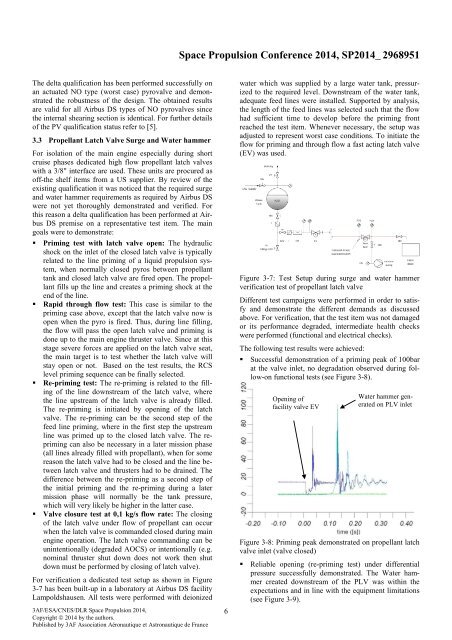
The following test results were achieved:<br />
• Successful demonstration of a priming peak of 100bar<br />
at the valve inlet, no degradation observed during follow-on<br />
functional tests (see Figure 3-8).<br />
Opening of<br />
facility valve EV<br />
Water hammer generated<br />
on PLV inlet<br />
Figure 3-8: Priming peak demonstrated on propellant latch<br />
valve inlet (valve closed)<br />
• Reliable opening (re-priming test) under differential<br />
pressure successfully demonstrated. The Water hammer<br />
created downstream of the PLV was within the<br />
expectations and in line with the equipment limitations<br />
(see Figure 3-9).