Power Factor Correction
Power Factor Correction
Power Factor Correction

Create successful ePaper yourself
Turn your PDF publications into a flip-book with our unique Google optimized e-Paper software.
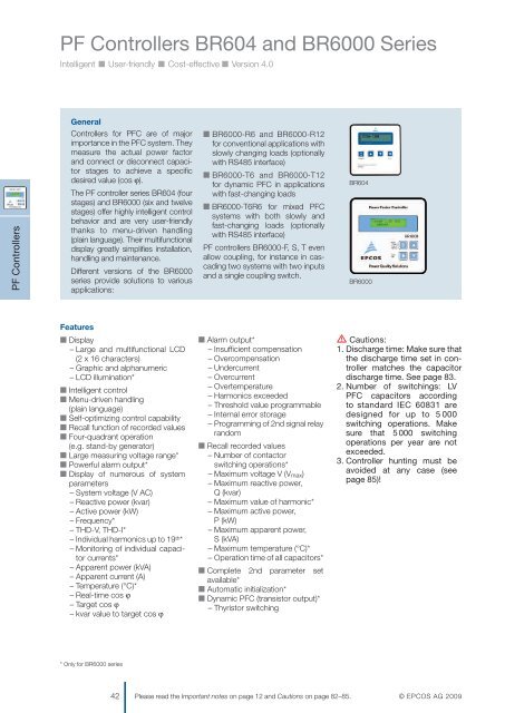
PF Controllers BR604 and BR6000 Series<br />
Intelligent ■ User-friendly ■ Cost-effective ■ Version 4.0<br />
General<br />
Controllers for PFC are of major<br />
importance in the PFC system. They<br />
measure the actual power factor<br />
and connect or disconnect capacitor<br />
stages to achieve a specific<br />
desired value (cos ϕ).<br />
The PF controller series BR604 (four<br />
stages) and BR6000 (six and twelve<br />
stages) offer highly intelligent control<br />
behavior and are very user-friendly<br />
thanks to menu-driven handling<br />
(plain language). Their multifunctional<br />
display greatly simplifies installation,<br />
handling and maintenance.<br />
Different versions of the BR6000<br />
series provide solutions to various<br />
applications:<br />
PF Controllers<br />
■ BR6000-R6 and BR6000-R12<br />
for conventional applications with<br />
slowly changing loads (optionally<br />
with RS485 interface)<br />
■ BR6000-T6 and BR6000-T12<br />
for dynamic PFC in applications<br />
with fast-changing loads<br />
■ BR6000-T6R6 for mixed PFC<br />
systems with both slowly and<br />
fast-changing loads (optionally<br />
with RS485 interface)<br />
PF controllers BR6000-F, S, T even<br />
allow coupling, for instance in cascading<br />
two systems with two inputs<br />
and a single coupling switch.<br />
BR604<br />
BR6000<br />
Features<br />
■ Display<br />
– Large and multifunctional LCD<br />
(2 x 16 characters)<br />
– Graphic and alphanumeric<br />
– LCD illumination*<br />
■ Intelligent control<br />
■ Menu-driven handling<br />
(plain language)<br />
■ Self-optimizing control capability<br />
■ Recall function of recorded values<br />
■ Four-quadrant operation<br />
(e.g. stand-by generator)<br />
■ Large measuring voltage range*<br />
■ <strong>Power</strong>ful alarm output*<br />
■ Display of numerous of system<br />
parameters<br />
– System voltage (V AC)<br />
– Reactive power (kvar)<br />
– Active power (kW)<br />
– Frequency*<br />
– THD-V, THD-I*<br />
– Individual harmonics up to 19 th *<br />
– Monitoring of individual capacitor<br />
currents*<br />
– Apparent power (kVA)<br />
– Apparent current (A)<br />
– Temperature (°C)*<br />
– Real-time cos ϕ<br />
– Target cos ϕ<br />
– kvar value to target cos ϕ<br />
■ Alarm output*<br />
– Insufficient compensation<br />
– Overcompensation<br />
– Undercurrent<br />
– Overcurrent<br />
– Overtemperature<br />
– Harmonics exceeded<br />
– Threshold value programmable<br />
– Internal error storage<br />
– Programming of 2nd signal relay<br />
random<br />
■ Recall recorded values<br />
– Number of contactor<br />
switching operations*<br />
– Maximum voltage V (V max)<br />
– Maximum reactive power,<br />
Q (kvar)<br />
– Maximum value of harmonic*<br />
– Maximum active power,<br />
P (kW)<br />
– Maximum apparent power,<br />
S (kVA)<br />
– Maximum temperature (°C)*<br />
– Operation time of all capacitors*<br />
■ Complete 2nd parameter set<br />
available*<br />
■ Automatic initialization*<br />
■ Dynamic PFC (transistor output)*<br />
– Thyristor switching<br />
V Cautions:<br />
1. Discharge time: Make sure that<br />
the discharge time set in controller<br />
matches the capacitor<br />
discharge time. See page 83.<br />
2. Number of switchings: LV<br />
PFC capacitors according<br />
to standard IEC 60831 are<br />
designed for up to 5 000<br />
switching operations. Make<br />
sure that 5 000 switching<br />
operations per year are not<br />
exceeded.<br />
3. Controller hunting must be<br />
avoided at any case (see<br />
page 85)!<br />
* Only for BR6000 series<br />
42 Please read the Important notes on page 12 and Cautions on page 82–85.<br />
© EPCOS AG 2009