ICM333 - ICM Controls
ICM333 - ICM Controls
ICM333 - ICM Controls

You also want an ePaper? Increase the reach of your titles
YUMPU automatically turns print PDFs into web optimized ePapers that Google loves.
Connections for Air Conditioning Only<br />
1. For non-heat pump applications, the heat pump select jumper must be in the Default (N.O.) position, and the HP terminals must be left unconnected.<br />
2. Set the Cutout Speed and the Hard Start Time to the appropriate positions for the type of motor you have (see below).<br />
Connections for Heat Pump Systems<br />
1. The Heat Pump terminals accept the 24 VAC signal from the reversing valve holding coil. Make a parallel<br />
connection from the reversing valve to the HP terminals.<br />
Note: Do not apply a voltage higher than 30 VAC to the HP terminals.<br />
2. If the Heat Pump is in the Heating mode and the reversing valve is energized, then N.O.<br />
the Heat Pump Select jumper must be in the Default (N.O.) position.<br />
3. If the Heat Pump is in the Heating mode and the reversing valve is not energized,<br />
then the Heat Pump Select jumper must be in the N.C. position.<br />
N.C.<br />
Mode of Operations<br />
When using temperature probes, the control will maintain condenser temperature between 7°F above and 18°F below dialed Temperature Setpoint. The dial Temperature Setpoint range is 70°F to 140°F<br />
When using pressure probes, the control will maintain condenser pressure between 20psig above and 40psig below dialed Pressure Setpoint. The dial Pressure Setpoint range is 35psig to 465psig.<br />
The is no correlation between dial temperature and pressure scales on the control<br />
When the motor starts running it will hard start for the length of time dictated by the hard start dial setting. After the hard start time has elapsed, the motor speed is controlled by the probe reading, temperature or<br />
pressure. The green light turns on when the motor runs at full speed.<br />
As the sensed temperature/pressure decreases, the output voltage decreases. The yellow light turns on during motor variable speed. The output voltage may decrease to the determined cutout speed dictated by<br />
the cutout speed dial. Upon reaching the cutout speed setting, the output voltage goes to zero volts. The yellow light turns off.<br />
Setting the Cutout Speed<br />
The cutout speed dial adjusts the motor voltage range. Set the cutout voltage dial according to the type of motor you have.<br />
Sleeve Bearing Motors: Set the cutout speed dial to the middle of the sleeve bearing range. In this range, the motor can run down approximately 40-50% of<br />
the full line voltage, which allows sufficient RPMs for cooling and lubrication.<br />
CAUTION!: With sleeve bearing motors, it is important not to adjust outside the sleeve bearing range or bearing failure may result.<br />
Ball Bearing Motors: Set the cutout speed dial to the MIN position in the ball bearing range. This position offers the greatest range of speed control. At the<br />
MIN setting the motor can run down to approximately 20-30% of the full line voltage.<br />
Note: After starting at the recommended settings for either sleeve or ball bearing motors, you can fine tune the cutout speed to achieve the desired results.<br />
Setting the Hard Start Speed<br />
During the Hard Start mode, full voltage is applied to the motor during startup to overcome windmilling and to lubricate the bearings.<br />
The position of the hard start dial determines the time period of the hard start mode. The dial can be adjusted between 0.2 seconds and approximately 4 seconds.<br />
Set the hard start dial according to the type of motor you have. If you have a ball bearing motor, set the hard start dial to the MIN position. If you have a sleeve bearing motor, set the<br />
hard start dial to the middle of the sleeve bearing range.<br />
After you begin at the recommended setting, you can fine tune the hard start time within the recommended range for the type of motor you have.<br />
It is recommended that you use the minimum possible hard start time to avoid blowing too much cold air over the condenser.<br />
The hard start mode applies full voltage to the motor for the set time period. Afterwards, the motor speed is dictated by the temperature sensor(s).<br />
Symptom<br />
Unit fails to start<br />
The fuse is blown and/or signs of<br />
damage on the unit<br />
The fan cycles from ON to OFF<br />
with little or no speed modulation<br />
The high pressure switch trips off<br />
Troubleshooting<br />
Problem<br />
Using an AC voltmeter, measure the voltage between the 24VAC terminals. It should read approximately 24 volts. Measure the line voltage between LINE1 and LINE2 to<br />
confirm that line voltage is present.<br />
If lights are flashing alternatively then no probe is connected or malfunction probe.<br />
When using a temperature probe, disconnect it and use an ohmmeter to measure the resistance between the wires. It should match the chart in Appendix A.<br />
When using a pressure probe, with power applied to the control use a voltmeter to measure volts DC between COMM and P1 or P2, where the wire is connected. The reading<br />
should be according to the chart in Appendix B.<br />
The unit has been miswired and may be permanently damaged.<br />
Reduce hard start stetting to minimum needed to accelerate the fan. Excessive hard start causes large pressure drops by running too much cold air over the condenser.<br />
Should the cycling persist, relocate the temperature probe up the condenser to increase sensitivity to temperature change and/or adjust the temperature setpoint.<br />
See Unit fails to start above<br />
Check the setpoint and reduce it if needed<br />
Appendix A<br />
Temperature vs. Probe Resistance<br />
°C °F Resistance (KΩ)<br />
0° 32° 32.7<br />
5° 41° 25.4<br />
10° 50° 19.9<br />
15° 59° 15.7<br />
20° 68° 12.5<br />
25° 77° 10.0<br />
30° 86° 8.1<br />
35° 95° 6.5<br />
40° 104° 5.3<br />
45° 113° 4.4<br />
50° 122° 3.6<br />
Appendix B<br />
Pressure vs. Voltage<br />
Pressure<br />
(psig)<br />
Voltage<br />
(Vdc)<br />
0 0.5<br />
50 0.9<br />
100 1.3<br />
150 1.7<br />
200 2.1<br />
250 2.5<br />
300 2.9<br />
350 3.3<br />
400 3.7<br />
450 4.1<br />
500 4.5<br />
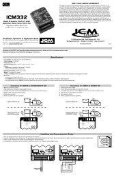
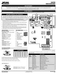
<strong><strong>ICM</strong>333</strong> Typical Installation<br />
Line 1<br />
Line Voltage<br />
Motor<br />
1<br />
Condenser<br />
Line 2<br />
Terminal to<br />
be used for<br />
480/600 VAC<br />
Motor<br />
2<br />
Sensor<br />
Sensor<br />
Control<br />
Transformer<br />
Sensor<br />
T-Stat<br />
Reversing Valve for<br />
Heat Pump<br />
<strong><strong>ICM</strong>333</strong><br />
can monitor<br />
two condensers