Horizontal Sand Filter Brochure
Horizontal Sand Filter Brochure
Horizontal Sand Filter Brochure

Create successful ePaper yourself
Turn your PDF publications into a flip-book with our unique Google optimized e-Paper software.
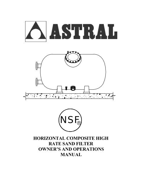
NSF R<br />
HORIZONTAL COMPOSITE HIGH<br />
RATE SAND FILTER<br />
OWNER’S AND OPERATIONS<br />
MANUAL
TABLE OF CONTENTS<br />
1. General<br />
1.1 Swimming pool filters<br />
1.2 Miami-Tank filters<br />
1.3 Selection of filters and installation<br />
1.3.1 <strong>Filter</strong> characteristics<br />
1.3.2 Installation characteristics<br />
2. Characteristics and dimensions<br />
2.1 Dimensions and media requirements<br />
2.2 Single filter system<br />
2.3 Dual filter system<br />
3. Installation<br />
3.1 General installation notes<br />
3.2 <strong>Filter</strong> installation<br />
3.3 Valve manifold and support installation<br />
3.4 Installation of the pressure gauges<br />
3.5 Testing of filter<br />
3.6 Installation of the media<br />
4. Normal operation<br />
4.1 Filtration<br />
4.2 Backwash<br />
4.3 Rinse<br />
4.4 Empty<br />
4.5 Close/Isolate<br />
4.6 Valve manifold table of operation<br />
5. Changing of the media<br />
6. Other recommendations<br />
7. Graph of filter head loss curve<br />
8. Replacement part drawings and numbers<br />
9. Warranty
1. General<br />
1.1 Swimming Pool <strong>Filter</strong>s<br />
<strong>Filter</strong>s are, without a doubt, the most important accessory used in the treatment of swimming pool water.<br />
Their purpose is to eliminate suspended particles from the circulating water, thus improving the clarity of the<br />
water.<br />
The principle of operation consists of passing the swimming pool water through a bed of sand which will<br />
retain any particles that are suspended in the water.<br />
It should be kept in mind that the filtration system consists of a number of elements, such as metering equipment,<br />
pumps, pool shell fittings and pipe work which ensure the correct suction and return flows that will<br />
affect the resultant condition of the treated water.<br />
Normally each country (possibly each state) will have its own standards for public and private pools. It is<br />
the responsibility of the installer to be aware of these codes before designing, specifying or installing any<br />
piece of equipment for a swimming pool.<br />
The quality of filtration depends on various factors: the size and shape of the media, the media bed depth,<br />
characteristics of the media such as granular size, density etc. A most important parameter is the water filtration<br />
rate. Other factors affecting the selection of a filter are the materials used for its construction, the<br />
working temperature, and the working pressure.<br />
1.2 Fiberglass <strong>Filter</strong>s<br />
Manufactured from polyester resin and fiberglass, they are virtually corrosion-proof. The internal fittings<br />
(diffuser and lateral system) are manufactured from PVC and polypropylene. They are unaffected by salt<br />
water and are normally manufactured for a working pressure up to 50 psi and a maximum working temperature<br />
of 122° F.<br />
Depending on the filtration velocity, filters are classified into three groups:<br />
• SLOW RATE FILTERS: Filtration velocities 5 to 10 GPM per sq. ft.<br />
• MEDIUM RATE FILTERS: Filtration velocities 10 to 15 GPM per sq. ft.<br />
• HIGH RATE FILTERS: Filtration velocities in excess of 15 GPM per sq. ft.<br />
For good filtration results, we recommend that filtration velocities of 15 GPM per sq. ft. are not exceeded,<br />
bearing in mind that the filtration velocity is dependent on the granular size of the media and the bed depth.<br />
It is also important to check all state and local codes that pertain to water filtration for swimming pools.
1.3 Selection of filters and installation<br />
1.3.1 <strong>Filter</strong> Characteristics<br />
It is recommended that the filtration system should filter at least 50% of the water from the surface of the pool as<br />
well as 50% from the lower levels of suction. The maximum turnover time for a public pool should not exceed 4<br />
hours, and for semi-public pools 6 hours. In the case of pubic pools for children the turnover should not exceed<br />
1½ hours. The times will vary from state to state and all local and state codes must be satisfied when using any<br />
filtration system.<br />
Example :<br />
If we have a public pool with a capacity of 150,000 gallons we need a filter capable of filtering this water in 4<br />
hours:<br />
150,000 gal / 4 hours = 37,500 gal/hour or 625 GPM<br />
To obtain a high quality of water filtration we recommend that the filtration velocity should comply with the following:<br />
Water parks 10 GPM per sq. ft.<br />
Commercial Pools 15 GPM per sq. ft.<br />
625 GPM / 10 GPM per sq. ft. = 62.5 sq. ft. of filtration required<br />
Now chose the filter or filters that meet this requirement. Remember it is possible to add filters together to obtain<br />
the correct amount of filtration area required. It is also a good idea to oversize the surface area required by<br />
10% or more, this will allow for better water quality. Whenever possible use more than one filter in conjunction,<br />
this will allow one filter to be serviced while one is still functioning.<br />
When sizing the plumbing for a filtration package be sure to keep in mind that the velocity of the water in the<br />
pipes is very important. Each state or country may have different maximums for velocity in the plumbing. The<br />
recommendations are as follows: the return line should not exceed 6.5 ft/s and the suction line should not exceed<br />
5 ft/s.<br />
1.3.2 Installation characteristics<br />
To insure the correct pump size, the required flow must be obtained by taking the system head into consideration.<br />
The system head is the added difficulty to move water through the system presented by using elbows, piping,<br />
tees, changes in elevation, etc. Normally, 34 ft of water (34’ of head) is sufficient but will depend upon each<br />
individual system.<br />
It is advisable to use the same number of pumps as filters, each pump producing the required flow for one filter.<br />
It is also recommended that the discharge from each pump is brought together in a single manifold to the filters.<br />
This will allow for greater flow rates for the backwash cycle.<br />
For each suction side, it is also recommended that the supply to each pump come from either a general suction<br />
manifold or balance tank. The suctions should be taken from both the surface and from the bottom of the pool.
2 Characteristics and Dimensions<br />
2.1 Dimensions and media requirements<br />
Model Filtration Area (A) (B) (C )<br />
Number (Sq. Ft.)<br />
11319 21 42" 52" 90"<br />
11325 26 42" 52" 105"<br />
11330 30 42" 52" 120"<br />
20895 34 42" 52" 135"<br />
20896 24 48" 60" 90"<br />
20897 29 48" 60" 105"<br />
20898 34 48" 60" 120"<br />
20899 38 48" 60" 135"<br />
20900 32 63" 78" 92"<br />
20901 37 63" 78" 105"<br />
20902 46 63" 78" 120"<br />
20903 51 63" 78" 138"<br />
07129 53 79" 90" 115"<br />
05110 75 79" 90" 160"
3. Installation<br />
3.1 General Installation notes<br />
BEFORE DOING ANY INSTALLATION IT IS VERY IMPORTANT TO READ THIS ENTIRE SEC-<br />
TION.<br />
Note: <strong>Filter</strong>s are supplied, pallet mounted and plastic shrink wrapped. Due to the weight and size it is recommended<br />
that mechanical means be employed to move the filters into position. It is also very important to inspect<br />
the filters carefully before unwrapping. Fiberglass filters can be damaged easily during transportation<br />
and is the responsibility of the installer to inspect at the time of delivery. Damages to filters from transportation<br />
that are not noted on the bill of lading are not covered by the warranty policy and all costs to repair will be<br />
the responsibility of the owner.<br />
Never put the media into the filter until it is in its final working position and all prior steps are complete<br />
.<br />
The filters should be accessible for periodic maintenance or media change. It is absolutely necessary to leave<br />
a minimu m access space around the filter(s). The following diagram below illustrates the minimums that are<br />
recommended for space, of course it is always better to have more space if possible.<br />
Fig. 3-1<br />
It is recommended that the filters be installed below the level of the pool surface and as a near as possible to<br />
the balance tank or the pool itself.<br />
The equipment room should be well ventilated and provided with adequate drainage capabilities so that should<br />
an emergency occur, resulting in flooding from a pipe, filter or pump, the water can be easily removed to<br />
avoid property damage. If drainage cannot be supplied directly from the equipment room, consideration<br />
should be given to the installation of an alternate system to remove water from the mechanical room.
3.2 <strong>Filter</strong> Installation<br />
Move the filter(s) into place by mechanical means if possible. Be careful not to hit the filter against something<br />
solid while positioning. Before continuing, be sure that the filter(s) is in the desired location with the<br />
connections facing the direction necessary for proper installation. It is also very important to make sure that<br />
the filter is sitting on a level hard surface.<br />
It is possible that during transportation, some of the internal components have loosened. It is now necessary to<br />
remove the filter lid and enter the filter, being careful not to break any of the connections. By hand, check the<br />
tightness of all the laterals in the bottom of the filter making sure they are firmly tightened. Also, while in the<br />
filter, check for any cracks or breaks in the body of the filter or the PVC internals that might have occurred during<br />
transportation using a flashlight.<br />
Inside the components box that is included with the filter there are two ¾” ball valves and gaskets for them.<br />
Install these valves with the gaskets onto the filter. One is for the top air purge nozzle located between the port<br />
connections. The second is located below the manhole and above the base of the filter.<br />
3.3 Valve manifold and supports installation<br />
There are many different styles of manifolds that are available: 4 valve, 5 valve, single filter, dual filter, triple<br />
filter, and automatic for each style. If the manifold is purchased with the filter, it will come with a specific set<br />
of installation instructions inside the box. These instructions will cover all necessary steps to installing the<br />
manifold.<br />
3.4 Testing of filter<br />
Before adding any sand to the filter, it is very important to test the system with water only!!! All filters are<br />
tested with high pressure before leaving the factory. It is possible that during transportation, the filter was damaged.<br />
It can be difficult to see some types of damages that may have occurred. It is important to test the system<br />
without sand first to check for leaks. Fill the system with water and then replace the lid and gasket. Run<br />
system as normal and check of leaks. If there is a problem with the test, contact customer service immediately.<br />
If sand is added before the test and there is a problem with the filter, the sand will need to be evacuated<br />
for inspection. The manufacturer will not pay for the removal and replacement of the sand for warranty or repair<br />
work, nor the labor to evacuate and replace the sand for repair work done due to transportation. This is<br />
also a good chance to check all of the plumbing for the system. Do not drain the water from the filter after<br />
the testing sequence.<br />
3.5 Installation of the media<br />
After the testing has been finished and the system is 100% operational, we need to add the filtration media required.<br />
Remove the lid and gasket from the filter as before. The filter should be full of water at this time. If<br />
the filter is not full of water, the filter needs to be filled at least to the diffusers before adding the media.<br />
Add the required amount of #20 silica sand to the filter. Now, replace the lid and gasket to the top of the filter.<br />
Be sure that the manhole cover is free of sand. If this is not free of sand, the gasket will not seat properly and<br />
could cause the filter to leak at the lid.<br />
Put the filter into backwash mode and run for about 5 to 6 minutes. This will level the sand inside the filter and<br />
will also remove the dust from the sand directly to waste. Put the valves into filter position and the system is<br />
ready for operation.
4 Normal Operation<br />
4.1 Filtration<br />
With the pump off, arrange the valves for filtration mode. Normally, while a filter is running, the inlet pressure<br />
is 12 to 15 psi and the outlet pressure is 6 to 9 psi. These are normal pressures when the filter is clean. As the<br />
filter media cleans the water, it traps particles of debris from the water inside the filter. These particles will<br />
make it more difficult for water to pass through, resulting in less water flow and a higher filter pressure. When<br />
this pressure difference is between 12 and 15 psi, it is time to backwash the system. Simply subtract the outlet<br />
pressure from the inlet pressure to determine your pressure differential.<br />
Example:<br />
Inlet pressure: 21 psi<br />
Outlet pressure: 7 psi<br />
Pressure differential: 14 psi<br />
4.2 Backwash<br />
Conclusion: The filter requires a backwash cycle.<br />
In filter beds, there are thousands of channels for water to pass through, trapping particulate matter. As time<br />
passes these channels become blocked and it becomes necessary to clean the filter bed to restore the filter to its<br />
optimum working condition by discharging the trapped particles to drain. The velocity of the water for the<br />
backwash cycle should be the same as for the filtration mode. This velocity should never exceed 20 GPM per<br />
sq. Ft. of surface area to prevent discharging sand to drain and possibly damaging the filter.<br />
The backwash cycle should be run for 3 to 5 minutes. It is advisable to fit a sight glass in the drain line close to<br />
the filter so that when a backwash is being carried out, one can see the water clearing and stop the backwash<br />
when the water is clean to avoid an unnecessary waste of water.<br />
5.0 Changing of The Media<br />
The procedure for changing the filter media is as follows:<br />
1. Turn off pumps.<br />
2. Remove lid and gasket from filter.<br />
3. Fill filter about ¾ full of water.<br />
4. Remove sand drain cap at bottom of filter (being careful not to get wet).<br />
5. Make sure that the sand does not block the sand passage.<br />
6. Using a hose from above, spray the sand as the filter drains to keep a steady flow.<br />
7. It may be necessary to enter the filter to remove the final ¼ of the sand.<br />
8. Replace sand drain lid, making sure the “o” ring is in good condition.<br />
9. Add the filtration media as described in section 3.6 of this manual.
6.0 Other recommendations of Interest<br />
♦<br />
♦<br />
♦<br />
♦<br />
♦<br />
♦<br />
♦<br />
Fiberglass filters are virtually corrosion resistant and need very little maintenance. It is advisable to clean<br />
the surface of the filter every 2 years, or whenever dirty, with a mild soap and water to maintain the looks<br />
of the filter.<br />
Every filter is equipped with a manual air vent fitted in the top of the filter. In addition, each filter has a<br />
water drain located in the bottom of the filter, which can be connected directly to a drain.<br />
When installing the valve manifold system it is advisable to use adequate pipe supports to support the<br />
weight of the manifold and the water flowing through it. Supports can be purchased or made on the job<br />
site.<br />
All filters can be completely automated.<br />
If the installation is to be shut down for long periods of time, it is advisable to drain the water during the<br />
period of non-use.<br />
Where freezing can occur, be certain to drain the filter before the opportunity to freeze can occur. Freezing<br />
of the water in a full filter will result in permanent damage to the fiberglass shell.<br />
Custom variations of these filters are available, please contact customer service with any questions.<br />
7.0 Graph of <strong>Filter</strong> Head Loss<br />
Pressure Loss<br />
14<br />
12<br />
10<br />
PSI<br />
8<br />
6<br />
4<br />
2<br />
0<br />
5 10 15 20<br />
GPM per Sq. Ft. of Filtration Area
FILTER PARTS BREAKDOWN
Fig. 1<br />
FIG. PART # DESCRIPTION<br />
1 0545-0212 NUT CAP<br />
2 7012112000 M12 STAINLESS NUT<br />
3 7013812000 M12 STAINLESS WASHER<br />
4 00473-0103 FIBERGLASS LID<br />
5 7234140120 LID GASKET<br />
Fig. 2<br />
MODEL # PART # DESCRIPTION<br />
11319 11319-0100<br />
11325 11325-0100<br />
11330 11330-0100<br />
20895 20895-0100<br />
20896 20896-0100<br />
20897 20897-0100<br />
20898 20898-0100<br />
20899 20899-0100<br />
20900 20900-0100<br />
20901 20901-0100<br />
20902 20902-0100<br />
20903 20903-0100<br />
07129 07129-0100<br />
05110 05110-0100<br />
DIFFUSER ASSEMBLY<br />
DIFFUSER ASSEMBLY<br />
DIFFUSER ASSEMBLY<br />
DIFFUSER ASSEMBLY<br />
DIFFUSER ASSEMBLY<br />
DIFFUSER ASSEMBLY<br />
DIFFUSER ASSEMBLY<br />
DIFFUSER ASSEMBLY<br />
DIFFUSER ASSEMBLY<br />
DIFFUSER ASSEMBLY<br />
DIFFUSER ASSEMBLY<br />
DIFFUSER ASSEMBLY<br />
DIFFUSER ASSEMBLY<br />
DIFFUSER ASSEMBLY
MODEL # PART # DESCRIPTION<br />
Fig. 3<br />
11319 11319-0200<br />
11325 11325-0200<br />
11330 11330-0200<br />
20895 20895-0200<br />
20896 20896-0200<br />
20897 20897-0200<br />
20898 20898-0200<br />
20899 20899-0200<br />
20900 20900-0200<br />
20901 20901-0200<br />
20902 20902-0200<br />
20903 20903-0200<br />
07129 07129-0200<br />
05110 05110-0200<br />
COLLECTOR ASSEMBLY<br />
COLLECTOR ASSEMBLY<br />
COLLECTOR ASSEMBLY<br />
COLLECTOR ASSEMBLY<br />
COLLECTOR ASSEMBLY<br />
COLLECTOR ASSEMBLY<br />
COLLECTOR ASSEMBLY<br />
COLLECTOR ASSEMBLY<br />
COLLECTOR ASSEMBLY<br />
COLLECTOR ASSEMBLY<br />
COLLECTOR ASSEMBLY<br />
COLLECTOR ASSEMBLY<br />
COLLECTOR ASSEMBLY<br />
COLLECTOR ASSEMBLY<br />
MODEL # PART # DESCRIPTION<br />
Fig. 4<br />
11319 204080<br />
11325 206080<br />
11330 206080<br />
20895 206080<br />
20896 206080<br />
20897 206080<br />
20898 206080<br />
20899 206080<br />
20900 206080<br />
20901 206080<br />
20902 208080<br />
20903 208080<br />
07129 208080<br />
05110 208080<br />
FILTER CONNECTION<br />
FILTER CONNECTION<br />
FILTER CONNECTION<br />
FILTER CONNECTION<br />
FILTER CONNECTION<br />
FILTER CONNECTION<br />
FILTER CONNECTION<br />
FILTER CONNECTION<br />
FILTER CONNECTION<br />
FILTER CONNECTION<br />
FILTER CONNECTION<br />
FILTER CONNECTION<br />
FILTER CONNECTION<br />
FILTER CONNECTION
MODEL # PART # DESCRIPTION<br />
Fig. 5<br />
11319 07126-0101<br />
11325 07126-0101<br />
11330 07126-0101<br />
20895 07126-0101<br />
20896 08126-0101<br />
20897 08126-0101<br />
20898 08126-0101<br />
20899 08126-0101<br />
20900 09126-0101<br />
20901 09126-0101<br />
20902 09126-0101<br />
20903 09126-0101<br />
07129 10125-0101<br />
05110 10125-0101<br />
FILTER BASE<br />
FILTER BASE<br />
FILTER BASE<br />
FILTER BASE<br />
FILTER BASE<br />
FILTER BASE<br />
FILTER BASE<br />
FILTER BASE<br />
FILTER BASE<br />
FILTER BASE<br />
FILTER BASE<br />
FILTER BASE<br />
FILTER BASE<br />
FILTER BASE<br />
FIG. PART # DESCRIPTION<br />
1 02579 3/4" BALL VALVE<br />
2 04659-0603 FLAT GASKET FOR BALL VALVE<br />
3 1414-0601 3/4" PURGE NUT<br />
4 00545-0204 PLASTIC WASHER<br />
5 074065012 FLAT GASKET FOR PURGE FITTING<br />
6 00473-0409 AIR PURGE FITTING<br />
7 00473-0407 GREY SLOTTED CAP<br />
Fig. 6
Fig. 7<br />
FIG. PART # DESCRIPTION<br />
1 7010110100 M10 X 100 STAINLESS BOLT<br />
2 7210089019 BOLT "O" RING - M10<br />
3 00687-0302 MEDIA DRAIN BULKHEAD FITTING<br />
4 00546-0202 WHITE BULKHEAD GASKET<br />
5 00546-0201 EXTERIOR BULKHEAD FLANGE<br />
6 7011910000 M10 STAINLESS WASHER<br />
7 7012110000 M10 STAINLESS NUT<br />
8 7730950050 MEDIA DRAIN COVER "O" RING<br />
9 00687 R 0301 MEDIA DRAIN COVER<br />
10 7013810000 M10 STAINLESS WASHER (LARGE)<br />
11 7012110000 M10 STAINLESS NUT<br />
12 00545-0307 PLASTIC NUT CAP