

DEMO - 1973 Colorized Mustang Wiring and Vacuum Diagrams
DEMO - 1973 Colorized Mustang Wiring and Vacuum Diagrams
DEMO - 1973 Colorized Mustang Wiring and Vacuum Diagrams

You also want an ePaper? Increase the reach of your titles
YUMPU automatically turns print PDFs into web optimized ePapers that Google loves.
31-01-02 CHARGING SYSTEM 3 1 -0 1-02<br />
BATTERY 0<br />
STARTER<br />
ON STARTER<br />
LOOPED OUTSIDE<br />
OF THE WlRE HARNESS<br />
SUPPLY WlRE TO<br />
VEHICLE EQUIPMENT<br />
ySATTERY<br />
ALTERNATOR<br />
SUPPLY WIRE TO<br />
VEHICLE EQUIPMENT<br />
TERMINAL<br />
TO<br />
EQUIPMENT<br />
VEHICLE<br />
.<br />
THUNDERBIRD, LINCOLN CONTINENTAL,<br />
FORD, MERCURY, METEOR< TORINO, MONTEGO, MUSTANG AND COUGAR AND CONTINENTAL MARK IP.<br />
MAVERICK, COMET. AND PINTO J 1431-B<br />
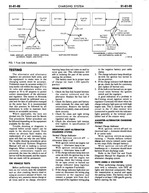
FIG. 1 Fuse Link Installation<br />
TESTING<br />
The alternator <strong>and</strong> alternator<br />
. regulator are precision built units, <strong>and</strong><br />
the equipment to make tests in the<br />
charging system must be accurate.<br />
Voltmeters must be accurate within 0.1<br />
(one tenth) volt within the range of 12 to<br />
16 volts <strong>and</strong> ammeters within one<br />
ampere at 30 to 65 amperes to permit .<br />
correct measurement of the alternator<br />
<strong>and</strong> regulator. The meters on Rotunda '<br />
equipment should be calibrated once a<br />
year <strong>and</strong> the date of calibration stamped<br />
on the meter face. It is recommended<br />
that this practice be followed by all<br />
technicians in order to maintain their<br />
meters at acceptable accuracy.<br />
Where applicable, the tests are<br />
divided into On Vehicle <strong>and</strong> On Bench<br />
Test procedures. Either procedure can<br />
be followed depending on the equipment<br />
available for the tests.<br />
Trouble shooting or diagnosis is<br />
required before actual repairs can be<br />
made in the electrical system. Even<br />
where an obvious fault makes the<br />
replacement of a unit necessary, you<br />
must still find out why the unit failed.<br />
The trouble shooting procedures given<br />
in the Electrical Systems Diagnosis<br />
Manual will aid in making a correct<br />
diagnosis. When a trouble is diagnosed<br />
correctly, unnecessary repairs are<br />
prevented, the time the vehicle is out of<br />
service will be.decreased, <strong>and</strong> the repairs<br />
that are made will be permanent.<br />
ON VEHICLE TESTS<br />
warning lamp does not come on <strong>and</strong>/or<br />
never goes out. This information will<br />
add in isolating the part of the system<br />
causing the problem.<br />
The battery must be in proper state<br />
of charge (at least 1.200 specific<br />
gravity).<br />
VISUAL INSPECTION<br />
1. Check the fuse link located between<br />
the starter solenoid <strong>and</strong> the<br />
alternator. Replace the fuse link if<br />
burned.<br />
2. Check the dattery posts <strong>and</strong> battery<br />
cable terminals for clean <strong>and</strong> tight<br />
connections. Remove the battery<br />
cables (if corroded), clean <strong>and</strong> install<br />
them securely.<br />
3. Check for clean <strong>and</strong> tight wiring<br />
connections at the alternator,<br />
regulator <strong>and</strong> engine.<br />
4. Check the alternator belt tension<br />
<strong>and</strong> tighten to specification (if<br />
necessary).<br />
INDICATOR LIGHT-ALTERNATOR<br />
CHARGING SYSTEM<br />
Normal Charge Indicator<br />
With Ignition switch off -<br />
Alternator lamp is off<br />
With ignition switch on (engine not<br />
running) - Alternator lamp is on<br />
With ignition switch on (engine<br />
running) - Alternator lamp is off<br />
1. If the charge indicator lamp does not<br />
come on with the ignition key in the<br />
on position <strong>and</strong> the engine not<br />
running, check the I wiring circuit<br />
for an-open circuit or burned out<br />
charge indicator lam^ .. (ignition .-<br />
Before performing charging system switcTh to regulator'l terminal).<br />
tests on the vehicle, note the complaint 2. If the charge indicator light does not<br />
such as: slow cranking, battery dead or come on, disconnect the wiring plug<br />
using an excessive amount of water, top connector at .the regulator .<strong>and</strong><br />
of battery wet, ammeter shows charge at connect a jumper wire from the I<br />
all times <strong>and</strong>/or no charge, alternator terminal of the regulator wiring plug<br />
to the negative battery post cable<br />
clamp.<br />
3. The charge indicator lamp should go<br />
on with the ignition key turned to<br />
the on position.<br />
4. If the charge indicator bulb does not<br />
go on, check the bulb for continuity<br />
<strong>and</strong> replace (if burned out).<br />
5. If the bulb is not burned out, an open<br />
circuit exists between the ignition<br />
switch <strong>and</strong> the regulator.<br />
A good indication of a problem in<br />
the I wiring circuit (ignition switch to<br />
regulator I terminal) will show when the<br />
charge indicator light goes out with high<br />
engine rpm. This is caused by an open<br />
circuit in the 15 ohm resistor wire<br />
(connected in parallel with the indicator<br />
light) generally at the terminal point<br />
(either end of the resistor wire).<br />
AMMETER-ALTERNATOR CHARGING<br />
SYSTEM<br />
Normal Charge Indicator<br />
With ignition switch off <strong>and</strong> no<br />
electrical load -Ammeter should show<br />
0 or center scale.<br />
With ignition sivitch on engine<br />
running - Needle deflects toward<br />
charge <strong>and</strong> returns toward center scale<br />
in. two steps (fully charged battery).<br />
With ignition switch off <strong>and</strong><br />
headlamps on - Ammeter should show<br />
between 0 <strong>and</strong> discharge scale.<br />
Refer to the Ford Car <strong>and</strong> Truck<br />
Diagnosis Manual for diagnosis of the<br />
alternator charging system.<br />
TESTS USING A VOLTMETER<br />
When performing charging system<br />
tests with a voltmeter, turn OFF all<br />
lights <strong>and</strong> electrical components. Place<br />
the transmission in neutral <strong>and</strong> apply<br />
the parking brake. The battery must be<br />
charged to at least 1.200 specific gravity<br />
before starting the test.


