the weller reman network
the weller reman network
the weller reman network

Create successful ePaper yourself
Turn your PDF publications into a flip-book with our unique Google optimized e-Paper software.
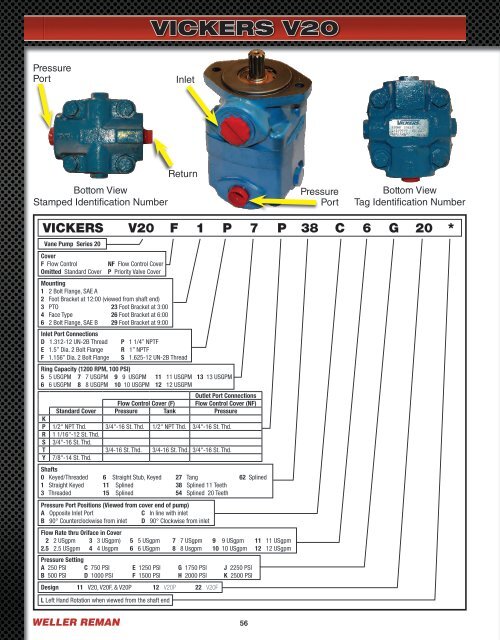
VICKERS V20<br />
Pressure<br />
Port<br />
Inlet<br />
Bottom View<br />
Stamped Identification Number<br />
Return<br />
Pressure<br />
Port<br />
Bottom View<br />
Tag Identification Number<br />
VICKERS V20 F 1 P 7 P 38 C 6 G 20 *<br />
Vane Pump Series 20<br />
Cover<br />
F Flow Control<br />
Omitted Standard Cover<br />
NF Flow Control Cover<br />
P Priority Valve Cover<br />
Mounting<br />
1 2 Bolt Flange, SAE A<br />
2 Foot Bracket at 12:00 (viewed from shaft end)<br />
3 PTO 23 Foot Bracket at 3:00<br />
4 Face Type 26 Foot Bracket at 6:00<br />
6 2 Bolt Flange, SAE B 29 Foot Bracket at 9:00<br />
Inlet Port Connections<br />
D 1.312-12 UN-2B Thread<br />
E 1.5” Dia. 2 Bolt Flange<br />
F 1.156” Dia. 2 Bolt Flange<br />
P 1 1/4” NPTF<br />
R 1” NPTF<br />
S 1.625-12 UN-2B Thread<br />
Ring Capacity (1200 RPM, 100 PSI)<br />
5 5 USGPM 7 7 USGPM 9 9 USGPM 11 11 USGPM 13 13 USGPM<br />
6 6 USGPM 8 8 USGPM 10 10 USGPM 12 12 USGPM<br />
Outlet Port Connections<br />
Flow Control Cover (F) Flow Control Cover (NF)<br />
Standard Cover Pressure Tank Pressure<br />
K<br />
P 1/2" NPT Thd. 3/4"-16 St. Thd. 1/2" NPT Thd. 3/4"-16 St. Thd.<br />
R 1 1/16"-12 St. Thd.<br />
S 3/4"-16 St. Thd.<br />
T 3/4-16 St. Thd. 3/4-16 St. Thd. 3/4"-16 St. Thd.<br />
Y 7/8"-14 St. Thd.<br />
Shafts<br />
0 Keyed/Threaded 6 Straight Stub, Keyed 27 Tang 62 Splined<br />
1 Straight Keyed 11 Splined 38 Splined 11 Teeth<br />
3 Threaded 15 Splined 54 Splined 20 Teeth<br />
Pressure Port Positions (Viewed from cover end of pump)<br />
A Opposite Inlet Port<br />
C In line with inlet<br />
B 90° Counterclockwise from inlet D 90° Clockwise from inlet<br />
Flow Rate thru Oriface in Cover<br />
2 2 USgpm 3 3 USgpm) 5 5 USgpm 7 7 USgpm 9 9 USgpm 11 11 USgpm<br />
2.5 2.5 USgpm 4 4 Usgpm 6 6 USgpm 8 8 Usgpm 10 10 USgpm 12 12 USgpm<br />
Pressure Setting<br />
A 250 PSI C 750 PSI E 1250 PSI G 1750 PSI J 2250 PSI<br />
B 500 PSI D 1000 PSI F 1500 PSI H 2000 PSI K 2500 PSI<br />
Design 11 V20, V20F, & V20P 12 V20P 22 V20F<br />
L Left Hand Rotation when viewed from <strong>the</strong> shaft end<br />
WELLER REMAN<br />
56